Honeywell TESTAIR 4 User manual

NU 1824591-00 -10/13
TESTAIR 4
Computerized Performance Tester for Air-Supplied Breathing Apparatus
SETUP GUIDE
EN
GUÍA DE INSTALACIÓN
ES
GUIDE D’INSTALLATION
FR
GUIDA ALLA CONFIGURAZIONE
IT
INSTALLATIEGIDS
NL
PRZEWODNIK KONFIGURACJI
PL
GUIA DE INSTALAÇÃO
PT

EN-1
EN
IMPORTANT
THESE INSTRUCTIONS ARE FOR EXPERIENCED PERSONNEL, TRAINED AND FAMILIAR WITH WEARING
BREATHING APPARATUS
CE regulations are applied to complete apparatus matching the CE certified configurations by notified bodies
that have carried out CE type examinations.
Failure to comply with this procedure immediately invalidates the CE marking.
To find out all the approved configurations, refer to the configuration tables, available on request.
HONEYWELL RESPIRATORY SAFETY PRODUCTS is continuously endeavouring to improve all its products
and the equipment supplied is subject to change without notice. Consequently, the information, illustrations
and descriptions provided in this document may not be used as a reason to demand the replacement of
equipment.
Being in possession of these instructions does not automatically authorise the holder to use TestAir 4; only
appropriate training will enable safety procedures to be followed.
HONEYWELL RESPIRATORY SAFETY PRODUCTS accepts no liability if the recommendations contained in
this document are not followed.
The recommendations in boxes have the following meanings:
IMPORTANT
Failure to follow the instructions in boxes could seriously damage the
equipment used and put the user in danger.
NOTE
Failure to follow the instructions in boxes could lead to incorrect use of
the equipment and result in damage to the equipment.
Warnings and Cautions
Do not open the TestAir 4’s case while it is powered up. Contact with the TestAir 4’s powered internal
circuitry may lead to death or serious injury.
SCBA Cylinders are under considerable pressure. Always follow the manufacturer’s recommendations for
proper handling when working with compressed air cylinders. Failure to follow the manufacturer’s
recommendations may lead to death or serious injury.
Electrical Requirements
The TestAir 4 is classified for use in the following electrical systems:
100-125 VAC, 50-60Hz using only 2A 250V Slow Blow Fuses
220-250 VAC, 50-60Hz using only 1A 250V Slow Blow Fuses

EN-2
TABLE OF CONTENTS
Warnings and Cautions ...........................................................................................1
Electrical Requirements ..........................................................................................1
1. Overview ........................................................................................................3
1.1 Installation Overview...........................................................................................................3
1.2 Note on Brand-Specific Software ........................................................................................3
1.3 Calibration Requirement......................................................................................................3
1.4 Software License.................................................................................................................3
2. Out of the box................................................................................................4
3. PC Requirements ..........................................................................................4
3.1 Software..............................................................................................................................4
3.2 Hardware.............................................................................................................................4
4. Software .........................................................................................................4
5. Hardware Setup.............................................................................................4
5.1 Connect the TestAir 4 to the PC..........................................................................................4
5.2 Turn on the power...............................................................................................................4
5.3 Install the microphone.........................................................................................................4
6. Launch the Software.....................................................................................5
6.1 Pre-Test Requirements.......................................................................................................5
6.2 Initial Login..........................................................................................................................5
6.3 Set up a User Account ........................................................................................................6
6.3.1 User Permission Levels .................................................................................................6
6.3.2 Create a New User.........................................................................................................6
6.3.3 Edit User Data................................................................................................................7
6.4 Add Apparatus Models........................................................................................................7
6.5 Add New Serial Number......................................................................................................9
6.6 Import Serial Numbers ......................................................................................................10
7. Connect the breathing apparatus to the TestAir 4...................................11
7.1 Identify the major parts......................................................................................................11
7.2 Attach the Facepiece.........................................................................................................12
7.3 Attach the high pressure manifold.....................................................................................12
7.4 Attach the medium pressure manifold...............................................................................13
8. Testing..........................................................................................................13
8.1 AutoAdvance feature.........................................................................................................13
8.2 Complete SCBA test .........................................................................................................14
8.3 Quick SCBA Test ..............................................................................................................14
8.4 Airlline Apparatus Test......................................................................................................14
8.5 Finalizing the test ..............................................................................................................14
8.6 Facepiece test...................................................................................................................15
8.7 Breathing Machine Test ....................................................................................................15
8.8 Cylinder Tracking ..............................................................................................................15

EN-3
1. Overview
The TestAir 4 is a computerized test bench designed
to evaluate the performance of a completely
assembled self-contained breathing apparatus (SCBA)
and other types of air-supplied respiratory protective
equipment.
This Setup Guide is designed to provide the user with
step-by-step instructions for the initial setup of the
TestAir 4.
Instructions for running tests are contained in the
TestAir 4 Help File.
1.1 Installation Overview
Prior to performing tests, the following items must be
accomplished:
1. Remove the TestAir 4 and the accessories from
the shipping box and verify that all parts are
present. See section 2 for the complete parts list.
Do not discard the shipping box and packing
materials –they are necessary for returning the
TestAir 4 to Honeywell Respiratory Safety
Products (HRSP) for its annual calibration or
maintenance.
2. Verify that your PC meets the OS and hardware
requirements as described in sections 3.1 and 3.2
below.
3. Install the software (see section 4 below).
4. Launch the software (see section 6 below). If this
is the initial use of the software, “Setup” is both
the user name and the password for the initial
opening of the software.
5. Create a user that has the rights to create and
modify apparatus data in the software. (see
section 6.2)
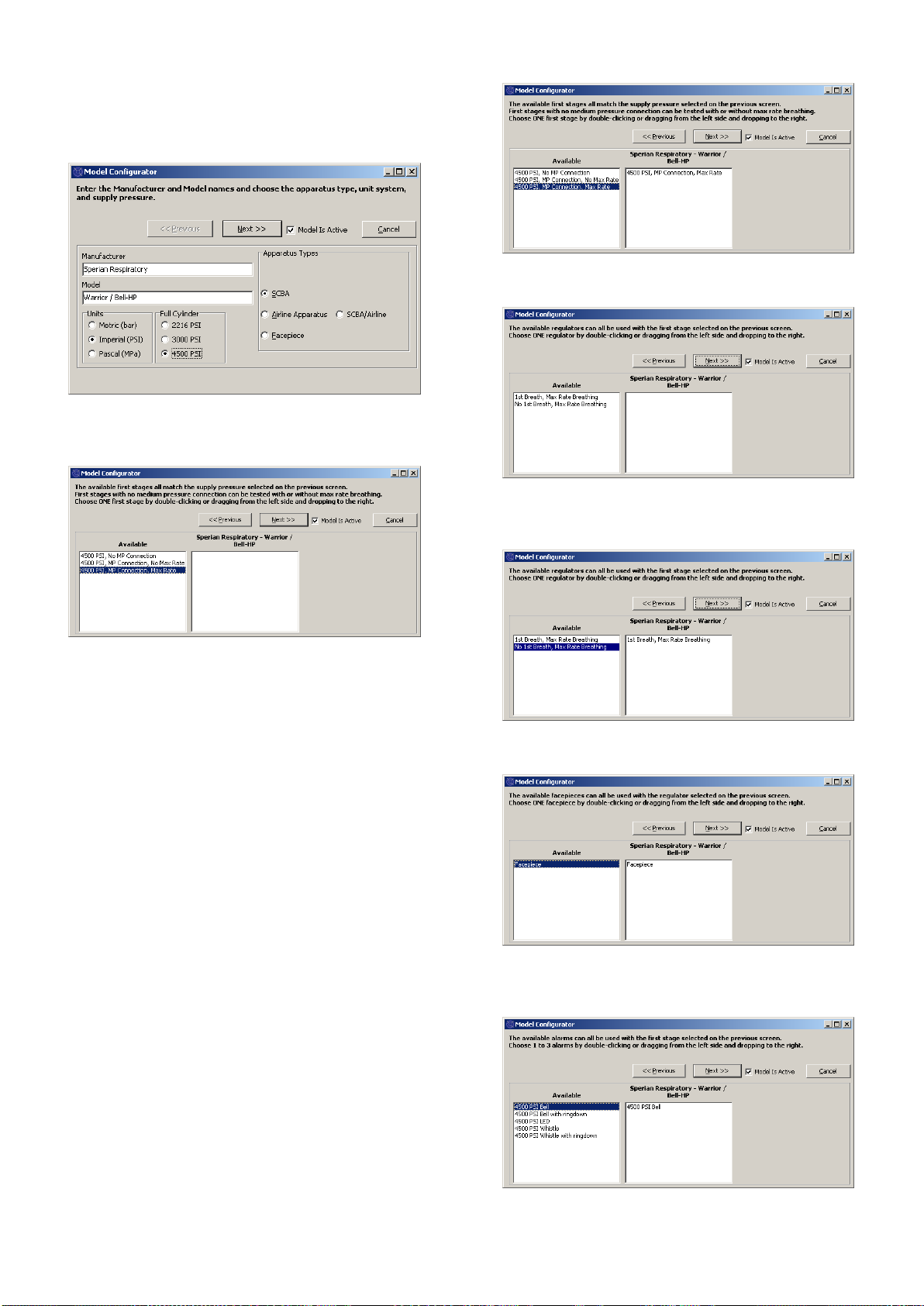
6. Enter information about the breathing apparatus
models into the software. This section can be
disregarded by users with manufacturer-specific
software. See section 6.3.
7. Assign the serial number of the breathing
apparatus to the model/apparatus info that was
created.
8. Attach the breathing apparatus to the TestAir 4
(see section 7 below).
9. Perform Tests. See the TestAir 4 Help File for
further information about testing.
1.2 Note on Brand-Specific Software
The TestAir 4 is the Honeywell Safety Product Original
Equipment Manufacturer (OEM) version of software
available in Europe.
For more information on the different OEM, please
refer to the PDF file ”Setup Guide Posi3 USB”
paragraph 1-2, attached to the TestAir 4.
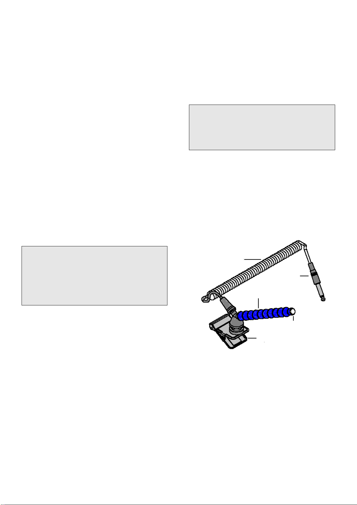
Use of the first stage manifold in conjunction with
brand-specific software allows the user to test
specific breathing apparatus to the tolerances
specified by the SCBA manufacturer and allows the
user to easily isolate problem components.
1.3 Calibration Requirement
The TestAir 4 must be calibrated annually to maintain
the accuracy of the internal transducers. Calibration
must be performed either by HRSP, or by a
Honeywell-authorized Service Center.
1.4 Software License
Each copy of TestAir 4 Software is licensed to the user
who purchased it. The name of the registered user will
appear during the software installation procedure.
The license information may be viewed at any time
through the Help - About screen.
The software license information is stored in the record
of each breathing test that is performed, and will be
displayed on the breathing test results when printed.

EN-4
2. Out of the box
The TestAir 4 is delivered with the following items:
TestAir 4
Medium Pressure Manifold
High Pressure Manifold for 200 bar
High Pressure Manifold for 300 bar
CD-ROM with BA Test Software
Setup Guide
USB Cable
Power Cable
“Air-Klick” – RD40 adaptor
RD40 blank gasket
Support for F1 facepieces tests
Microphone
3. PC Requirements
3.1 Software
The TestAir 4 Software has the following OS
requirements:
Windows XP to Windows 7, 32 or 64 bit.
In order to install the software, the software installer
must log on as system administrator.
3.2 Hardware
Make sure that your computer system meets the
minimum requirements prior to attempting to
install or use TestAir 4 Software. Inadequate
system resources may prevent the software
from operating properly on your system. The
minimum specifications for the computer used
to run TestAir 4 Software vary according to the
operating system used.
Pentium 4 processor 2.0 GHz or higher
512 MB RAM
50 MB hard drive space
USB 2.0 Port
CD-ROM drive (for installation of software)
4. Software
For sofware installation and database setup, please
refer to the PDF file, “Setup Guide Posi3 USB”
paragraph 4, attached to the TestAir 4.
5. Hardware Setup
5.1 Connect the TestAir 4 to the PC
The TestAir 4 is connected to the PC via USB cable.
Once the software is installed and the TestAir 4 is
assembled, use the USB cable to attach the TestAir 4
to the PC.
5.2 Turn on the power
To turn the TestAir 4 on, simply plug the power cord of
the TestAir 4 into a grounded outlet and flip the rocker
switch located on the rear panel of the TestAir 4
chassis.
Note: HRSP recommends that the TestAir 4 be
plugged into a surge protector. Failure to use a
surge protector may lead to sporadic loss of
communication between the TestAir 4 and the PC.
Do not attach the pressure-reducing manifold, or
mount an SCBA facepiece on the test head prior
to turning the TestAir 4 on. Doing so prior to
completion of the electronic self test and startup
sequence may result in damage to the TestAir 4
and/or incorrect test data.
The USB Drivers must be installed prior to launching
the TestAir 4 software. The USB driver installation is
covered in section 4.1 above (see step 21) and is also
discussed in the TestAir 4 Installation Help File.
5.3 Install the microphone
The microphone is need to be installed prior to
launching the software.
1. Plug the microphone into the port located on the
TestAir 4’s left front panel over the medium
pressure inlet.
Microphone and Carrier Arm Assembly
2. The software will automatically recognize the
microphone when the TestAir 4 is initialized.
The microphone is only used in the Complete
SCBA Test. For further instructions on using the
microphone, see the TestAir 4 Help File.
Coiled Cable
Jack
Flexible arm
Microphone
Clip

EN-5
6. Launch the Software
To launch the software, either double click on the
TestAir 4 icon located on your PC’s desktop screen or
click on the start button to access All Programs /
Sperian / Posi3 USB / Fenzy / BATest / BATest.exe
6.1 Pre-Test Requirements
Before the software will allow the testing of breathing
apparatus, the following requirements must be met:
1. Log in to the software (see section 6.2).
2. Set up a new user account with the ability to
create and test apparatus in the software. The
Setup User doesn’t have these rights, so at least
one new user must be created (See section 6.3).
3. Create an apparatus model in the software (See
section 6.4). Users with OEM software versions
will not have this option because the apparatus
models are included in the OEM software’s built-in
database and cannot be modified.
4. Assign a serial number to the apparatus you want
to test (See section 6.5)
6.2 Initial Login
At the initial software launch, there will be no system
users in the database, so an initial User ID and
Password are used to enter the software.
The initial User ID and password are
both “Setup”.
Note: User ID and Password are case sensitive.
After successful login, the software will prompt the
user to open the test results database that was created
during the installation procedure (see section 4.1
step 19 above).
Select the database and click Open.
The software will offer the option to search for software
updates and/or manufacturers bulletins.
If you wish to check for either of these items, click on
the appropriate options and then click Check.
Click “Done” to proceed to the initialization.
At the initialization screen, click the “Initialize TestAir 4”
checkbox to establish communication with the
instrument. The software must be able to communicate
with the TestAir 4 in order to perform tests.

EN-6
The Transducer Stability Test screen will be shown.
Once the Transducer Stability Test is passed the main
screen will be shown.
6.3 Set up a User Account
A new user with the ability to test breathing apparatus
must be created before testing can occur.
The Setup user has the ability to create new users, but
does not have the ability to test apparatus.
6.3.1 User Permission Levels
User access is divided into five levels.
Level 0: No longer allowed to use the software
Level 1: View Test Results
Level 2: Perform and View Tests
Level 3: Add Users, View Tests
Level 4: Perform and View Tests, Modify Apparatus
Data.
6.3.2 Create a New User
1. To create a new user, click on Setup / Users / User
List.
The User List screen will be shown.
2. Click on the +button to add a new user.
3. Enter the user’s information (as needed). The User
ID field and the Password field must be completed.
4. Set the Permissions level as needed.
5. Click on the Check button to save the information.

EN-7
6. Click Done when finished adding users.
6.3.3 Edit User Data
To edit an existing user’s information, enter the User
List as described above and click on the up arrow.
Once the user’s information has been changed, click
on the Check button to save the information.
6.4 Add Apparatus Models
Note: The Model Configuration Wizard is only available
in Standard Version TestAir 4 software.
All SCBA are made up of similar components including
a facepiece, a first stage regulator, a second stage
regulator, alarms, gauges and an air cylinder. Although
every SCBA is unique, there are general similarities
from model to model that HRSP uses to set the
appropriate baseline values for testing these
components.
The Model Configuration Wizard allows the user to
select components to create specific models from the
available of SCBA, Airline Apparatus, and Facepieces
that are used in testing.
Once the type of apparatus is selected, the Model
Configuration Wizard will automatically run through the
appropriate setup procedure. The user will need to
configure the model so that it matches the physical
specifications of the apparatus.
The testing procedure is automatically defined for the
apparatus model that is selected at the time of testing.
That apparatus is configured in the software by this
procedure.
The user entering apparatus information must have
level 4 software access or the Add New Model and/or
Add New Serial Number options may be unavailable.
See section 6.3.1 for a description of user software
permissions.
1. To enter a new apparatus, first select Setup /
Apparatus / Add New Model.
2. The Choose Model Screen will be shown and will
show a list of all models that are available for
testing. If this is the initial software launch, the
fields will be blank.
3. Click on New to enter the Model Configurator.

EN-8
4. Enter the Manufacturer Name and the Model
Name. Then select the units (Metric, Imperial or
Pascal), and select the type of apparatus (SCBA,
Airline Apparatus, SCBA/Airline or Facepiece).
5. Once the basic configuration of the apparatus is
entered, make sure that “Model Is Active” box is
selected and click “Next”.
6. At the First Stage Selection screen Double Click
on the appropriate first stage connection from the
left column. The selection should then appear in
the right column.
In this example, we’re configuring the first stage
for a 300 bar SCBA, so only first stages that can
be used with 300 bar are shown:
300 bar, No MP Connection
300 bar, MP Connection, No Max Rate
300 bar, MP Connection, Max Rate
Note: MP Connection stands for Medium Pressure.
For SCBA that are entered into the software with a
Medium Pressure connection in the Standard
software, the medium pressure readings will be
shown on tests where it is appropriate. The
Standard Software does not contain tolerances for
the medium pressure tests, so there will be no
indication whether the medium pressure portion of
the tests passes or fails.
All brand-specific versions of TestAir 4 Software
include Medium Pressure tests where appropriate (as
defined by the manufacturer). The inclusion of the
Medium Pressure connection allows the user to test
the output of the first stage according to the
manufacturer's specifications.
7. Once the selection is shown in the right column,
click “Next”.
8. At the Regulator selection screen, double click on
the appropriate regulator from the Available
column so that it appears in the column at right.
9. Once the selection is shown in the right column,
click “Next”.
10. Double click on the Facepiece from the Available
column so that it appears in the column at right.
Then click “Next”.

EN-9
11. At the Alarms Selection screen, double click on the
appropriate Alarm from the Available column so
that the alarm appears in the column at right and
click “Next”.
12. At the Gauge Selection screen, double click on the
appropriate gauge from the Available column so
that the gauge appears in the column at right and
click “Finish”.
Once the model has been configured, the software will
return to the Choose Model screen and the new model
will be shown in the box at left. When selected, the
components of that model will be shown in the box at
right.
13. Click OK when finished adding models.
6.5 Add New Serial Number
Prior to assigning a serial number to an apparatus, the
apparatus model information must be added to the
models database.
1. To add a new serial number to the software, first
select Setup / Apparatus / Add New Serial
Number.
The Choose Model Screen will be shown.
The default settings for the Choose Model screen are
to display Active Breathing Apparatus. Options at the
bottom allow that user to select from Breathing
Apparatus or Cylinders and from Active, Inactive or All.
Inactive items cannot be selected for testing. To
change the active / inactive setting for an item, right
click on it and select “Set as Active” or “Set as
Inactive” (as appropriate) from the menu options.
2. If the model for the serial number to be entered is
shown, click on it to select it and click OK.
To add a new model, click the “New” button and refer
to section 6.4 for instructions on adding a new model.

EN-10
3. Enter the serial number and other specific
information about the apparatus.
Some information shown on the serial number screen
can be affected by the options chosen in the Setup /
Options screen. The options can be displayed and
changed by using the Actions button at the bottom of
the screen.
Required fields are marked in red. The Serial Number
field is always mandatory. The list of other required
fields can be changed in the options menu.
The display of auxiliary IDs and overhaul dates is also
controlled in the options screen. See the TestAir 4
Help File for further details.
4. To enter another serial number that is identical in
configuration to the first one, click on “Retain
entries when adding another serial number” at the
bottom, then click on “Add Another”. The software
will create a new Enter Serial Number Information
screen while retaining the other information that
has been entered.
5. To enter another apparatus that has a different
configuration from the first one, click “Add Another”
and leave “Retain entries….” unchecked.
6. Once all of the apparatus have been entered, click
“Accept” at the lower right.
6.6 Import Serial Numbers
For those who have been using the PosiChek3
Titanium Edition 32-Bit Software, it is possible to
import apparatus information from the existing MS
Access database into the new PostgreSQL database.
To start the import, click on the File Menu followed by
Import / Serial Numbers from Access Database.
The Access Import Wizard screen will be shown.
Click Next to select the Access database that will be
imported into the PostgreSQL database.
A file –open dialog box will be shown and will
automatically open at the default location for test
results in the PosiChek3 software. If the database is
located somewhere else, use the browse function to
navigate to that location and select the database.
Click on a database to select it and click Open. The
Import Serial Number screen will be shown along with
the information about the Access Database.

EN-11
Click Next to choose the models for import.
The screen will list all of the models in the selected
database that have serial numbers assigned to them.
Select a row by clicking in it so the whole row appears
highlighted and click the “Choose Model” button at
lower left. The Choose Model screen will be shown. If
the model that is being exported from Access matches
an existing model in the new PostgreSQL database,
then select it. Otherwise, click the “New” button and
add the model specifications into the new database.
Continue with this process of selecting the serial
numbers from the access database and exporting
them into the new PostgreSQL database until all
models have been entered.
Once all serial numbers have been successfully
imported into the PostgreSQL database, click Next.
The software will show the numbers of serial numbers
that were imported, and will show those that were not
imported. Apparatus with serial numbers already
present in the PostgreSQL database will not be
imported.
To import the complete content of TestTair 3
database, you must have the TestTair 3 software
installed on the same PC.
7. Connect the breathing
apparatus to the TestAir 4.
Now that the software is installed and running, and the
TestAir 4 is assembled, it is time to connect the
breathing apparatus to the TestAir 4. One of the
strengths of the TestAir 4 is its adaptability. For simpler
tests, the breathing apparatus’s facepiece serves as
the only interface between the TestAir 4 and the
breathing apparatus. More complex tests require the
use of a series of manifolds to deliver pressure levels
from points in the breathing apparatus’s airstream to
the TestAir 4’s internal transducers. Every breathing
apparatus is different, so specific parts and instructions
may be required for your breathing apparatus to be
connected to the TestAir 4.
The Complete SCBA Test requires the following
connections between the SCBA and the TestAir 4:
1. The breathing apparatus facepiece is put on the
TestAir 4’s anatomically correct test head, just as it
would be placed on the head of a person. See
section 7.2 below.
2. The appropriate high or medium-pressure manifold
is inserted between the cylinder and the first stage
regulator and then connected to the high-pressure
inlet fitting located at the lower right side on the
front face of the TestAir 4. See section 7.3.
3. If possible, the high pressure manifold is
connected from a location downstream of the first
stage regulator and upstream of the facepiece to
the medium pressure inlet, which is located at the
lower left side on the front panel of the TestAir 4.
(See section 7.4)
7.1 Identify the major parts
First identify the three manifolds that are included with
the TestAir 4*. Each of the manifolds comes with a
factory label that identifies it by name and part number.
Medium pressure manifold
The Medium pressure manifold can be recognized by
its CEJN-fitting and gasket for demand valve
connection.

EN-12
High pressure manifold
The high pressure manifold can be recognized by its
stainless steel T-fitting and handwheel.
Support to test F1 facepiece with helmet
The support is to placed between base box and head
and fixed by the screws of the head.
Adaptor for facepiece with “Air-Klick” system
The adaptor is used to test the tightness of the
facepieces with “Air-Klick” system. The adaptor is to be
plugged on facepieces and RD40 screw blank can be
installed for tightness test
RD40 screw blank
The RD40 screw blank is used with “Air-Klick” adaptor
for facepiece tightness test
7.2 Attach the Facepiece
Position the facepiece squarely on the test head, and
tighten the straps evenly. Make sure the face piece’s
inner sealing surface is flat, sealed to the test head,
and that nothing compromises the integrity of the seal.
Make sure the nose cup is positioned over and across
the test head nose.
Do not connect the second stage regulator to the
facepiece until the software instructs you to do so. The
facepiece must be vented and open to ambient air
pressure when the facepiece leak test is started.
For F1 attachment system use the support described
earlier.
7.3 Attach the high pressure manifold
1. Turn off the cylinder valve on the SCBA to be
tested and depressurize it by using the bypass.
2. Disconnect the SCBA from the cylinder. If the
cylinder will not be used as the pressure source for
testing, it can be removed during testing.
3. Select the manifold that matches the supply
pressure of the SCBA and connect the handwheel
on the single end of the pressure-reducing
manifold to the TestAir 4 through the high pressure
inlet fitting located on the lower right front panel of
the TestAir 4. Make sure the handwheel is tight.
The correct manifold must be used to ensure
the correct results during the bypass flow test.
Use of the incorrect manifold can lead to
incorrect bypass flow test results, serious
injury, or death.
If a pressure supply other than a cylinder is
used, make sure the supply regulator is set to
the appropriate pressure.
Do not attempt to service SCBA without the
proper training from the SCBA’s manufacturer.

EN-13
4. Connect the High Pressure manifold following the
previous picture to TestAir 4, air source and
breathing apparatus.
Make sure the manifold does not kink!
Kinking can cause the hose to rupture, which
can lead to serious injury, or death.
5. Connect the SCBA to the T-fitting on the manifold.
7.4 Attach the medium pressure
manifold
An adapter is required to connect the first stage
manifold to the breathing apparatus. First stage
manifold adapters are specific to the SCBA and are
only available from the SCBA manufacturer.
Always follow the breathing apparatus
manufacturer’s instructions when connecting
the first stage to the TestAir 4.
You are now ready to begin testing your breathing
apparatus. Refer to the help file for further instructions.
The help file can be launched from the software at any
time by using the F1 key.
8. Testing
The Test menu allows you to choose a test sequence
to perform on the Posi3 USB. The Complete SCBA
Test sequence should be chosen if you wish to do an
annual flow test on an SCBA.
8.1 AutoAdvance feature
The AutoAdvance feature is intended to allow
experienced users to speed up the testing process. It
can be turned on and off in the Pressurization screen,
and on the Tests tab of the Setup - Options screen.
The AutoAdvance feature requires a higher supply
pressure, and is probably not convenient to use unless
you have a cascade system or large volume cylinder to
supply your air.
The differences in the test procedure with
AutoAdvance turned off or on are described below.
AutoAdvance OFF (default)
1. Required supply pressure to start a test is
around 110 bar or 220 bar. (Some tests may
require a higher or lower supply pressure.)
2. Settling time is required whenever the system
is pressurized.
3. The user is required to click OK to indicate the
pressure supply valve is closed.
4. The pressurization screen is always shown if
the user is required to close the supply valve.
Static pressure port
Mouth
Medium
pressure
inlet fitting
High pressure inlet fitting
for pressure reducing manifold
Air source
TestAir 4
Breathing
apparatus

EN-14
AutoAdvance ON
1. Required supply pressure is 15 or 30 bar
higher than the required supply pressure
without AutoAdvance. The required pressure
with AutoAdvance on and off is displayed at
the bottom of the pressurization screen. If you
are unable to reach the required pressure, you
can uncheck the box to turn AutoAdvance off
and continue with the lower supply pressure.
2. Settling time is only required for the high
pressure leak test.
3. The software instructs the user to close the
supply valve, but the user is not required to
click OK to acknowledge this, except for the
high pressure leak test. The software will just
continue.
4. The pressurization screen is only shown if the
supply pressure is lower than the required
pressure. Experienced users know exactly
when pressurization is required, and will
normally open the supply valve before the
pressurization screen would be shown.
AutoAdvance cannot cause a test to pass when it
should have failed.
If a user fails to close the supply valve at the
proper time, the worst that can happen is that
air will be wasted because it is breathing with
the valve open. After a couple of breaths, the
software will start to flash a message: "ARE
YOU SURE you closed the pressure supply
valve?" If the valve is left open during the
breathing test, it may trigger a message that
the manifold volume is too large.
The user is still required to click OK to indicate
the pressure supply valve is closed for high
pressure leakage. This is the one test where
the software cannot tell if the supply valve is
closed.
For all tests other than high pressure leakage,
settling time is only required to make sure the
pressure remains above the required minimum
after the supply valve is closed. This is
compensated for by requiring a higher supply
pressure to start the test.
8.2 Complete SCBA test
After clicking the New Test button on the Complete
SCBA Test screen, the Choose Model screen will be
shown. Click the model you wish to test and click OK.
Only models that are specified as SCBA or
SCBA/Airline will be shown. If the model you wish to
test is not shown, you can Add a new model (in the
Standard software) or use the Show Only button (in
OEM versions of the software) to show models with
different features.
Once you have chosen the model to be tested, the
Choose Serial Number screen will be shown. Only
serial numbers for the model you chose will be shown.
Select the serial number you wish to test by clicking in
a row and clicking OK.
After you select the serial number, the Test Header
information screen may be shown. It displays the
information that will be saved in the test header. You
can choose not to show this screen by unclicking the
Show Test Header Information checkbox. You can
reset the option to show it in the Options screen. If you
are tracking customer information, you will select the
customer in this screen. Click OK when you are done
with the Test Header Information screen.
You will be returned to the Complete SCBA Test
screen. All tests that have requirements in the model
tolerances will automatically be checked. You can
uncheck any tests if you do not want to perform them.
8.3 Quick SCBA Test
The Quick Test is intended to be a quick way to test
that an SCBA is still functioning properly, but it does
not thoroughly test every part of the SCBA. Therefore
it cannot be used for annual flow testing. The Quick
Test includes the same Visual Inspection, Facepiece
Leak Test, Activation/Static Pressure Test, and
Breathing Machine test that are used in the Airline
Apparatus test. If the medium pressure is hooked up,
the static medium pressure and medium pressure
change will be included in the Activation/Static
Pressure test results. The pressure gauge, high
pressure leak, alarm, and bypass tests that are done in
the Quick Test do not use the functionality of TestAir 4.
Since some users wish to schedule and track Quick
Tests (perhaps as a monthly test) a separate
notification is provided for tracking Quick Tests. Note
that this is different from TestAir 3 software, where the
Complete Test notification could also be used to track
Quick Tests.
8.4 Airline Apparatus Test
The Airline Apparatus Test is used to test all
components of an airline apparatus. The test
sequence consists of a Visual Inspection, Facepiece
Leak Test, Activation/Static Pressure Test, Standard
and Max Rate Breathing Tests, and Bypass Test.
Before starting the test you may launch the options
screen.
If all parts of an airline apparatus test are performed,
and they all pass, then the date the last successful
complete test was performed will be updated to today's
date, and the date the next test is due will be updated
as specified by the options.
8.5 Finalizing the test
The Finalize Test screen is shown after the Complete
SCBA Test or Airline Apparatus Test is performed. The
screen informs you if the last test and test due
dates will be updated. It also gives a summary of any
required tests that were failed or not performed. If any
of the auxiliary IDs associated with the serial number
need to be changed, this can be done on this screen.
To close the screen you can choose to save the test
and continue, delete the test and continue, or retest.

EN-15
8.6 Facepiece test
The Facepiece Test sequence is intended to test the
facepiece only, when facepieces are being tested
separately from the rest of the SCBA. The test
sequence includes the Visual Inspection, Facepiece
Leak Test, and Breathing Machine Tests.
All SCBA and Airline Apparatus are shown when
choosing the model for testing. You should choose the
model that matches the SCBA being used for the
breathing test, as well as the facepiece.
The same Visual Inspection checklist is shown as for
complete SCBAs. Obviously, only the components
contained in a facepiece should be inspected during a
Facepiece Test.
8.7 Breathing Machine Test
The breathing machine test allows you to test the
dynamic pressures at different breathing rates and test
durations. It is normally only used for diagnostic
purposes. The test will not start automatically because
the user is allowed to set the breathing rate and
duration of the test. Click the Start Breathing button
when you are ready to start the test.
8.8 Cylinder Tracking
Cylinder tracking does not use the functionality of the
TestAir 4 device. It is used to keep records of the
hydrostatic test dates of your cylinders. To update the
hydrostatic test date, you must first choose the serial
number to be updated. If the model or serial number of
the cylinder you wish to track is not in the list you are
shown, you may enter a new modelor serial number.
(New models may only be entered in the Standard
version of the software.)
When the serial number is chosen, the serial number
information and parameters of the model will be
displayed on the screen. You may click the retire
button to retire the cylinder, or enter the most recent
hydrostatic test date in the box. Click Accept when you
are done. If you wish to track another serial number,
click Choose Serial Number again. Otherwise, click
Close to exit the screen.

ES-1
ES
IMPORTANTE
ESTAS INSTRUCCIONES ESTÁN DIRIGIDAS A PERSONAL CON EXPERIENCIA Y FORMACIÓN,
FAMILIARIZADO CON LA UTILIZACIÓN DE APARATOS DE RESPIRACIÓN
Se aplican los reglamentos CE a los aparatos completos correspondientes a las configuraciones certificadas
CE por organismos notificados que han llevado a cabo exámenes CE de tipo.
El incumplimiento de este procedimiento invalida el marcado CE.
Para conocer todas las configuraciones aprobadas, consultar las tablas de configuración, disponibles previa
solicitud.
HONEYWELL RESPIRATORY SAFETY PRODUCTS se esfuerza continuamente en la mejora de todos sus
productos y el equipo suministrado estará sujeto a cambios sin previo aviso. En consecuencia, la
información, ilustraciones y descripciones proporcionadas en el presente documento no podrán ser
utilizadas como motivo para solicitar la sustitución del equipo.
La posesión de estas instrucciones no autoriza automáticamente al portador al uso de TestAir 4; únicamente
la formación apropiada habilitará los procedimientos de seguridad a seguir.
HONEYWELL RESPIRATORY SAFETY PRODUCTS no se hará responsable si no se siguen las
recomendaciones del presente documento.
Las recomendaciones en cuadros de texto significan lo siguiente:
IMPORTANTE
El incumplimiento de las instrucciones en cuadros de texto podría
perjudicar seriamente al equipo utilizado y poner en peligro al usuario.
NOTA
El incumplimiento de las instrucciones en cuadros de texto podría dar
lugar al uso incorrecto del equipo y dañarlo.
Advertencias y precauciones
No abrir la caja del TestAir 4 mientras esté encendido. El contacto con el circuito interno del TestAir 4 puede
provocar la muerte o lesiones graves.
Los cilindros SCBA se encuentran a una presión considerable. Seguir siempre las recomendaciones del
fabricante para una manipulación correcta cuando se trabaje con cilindros de aire comprimido. El
incumplimiento de las recomendaciones del fabricante pueden provocar la muerte o lesiones graves.
Requisitos eléctricos
El TestAir 4 está clasificado para su uso en los siguientes sistemas eléctricos:
100-125 VAC, 50-60Hz utilizando solo fusibles lentos de 2A 250V
220-250 VAC, 50-60Hz utilizando solo fusibles lentos de 1A 250V

ES-2
ÍNDICE
Advertencias y precauciones..................................................................................1
Requisitos eléctricos ...............................................................................................1
1. Introducción...................................................................................................3
1.1 Descripción general de la instalación..................................................................................3
1.2 Nota sobre el software específico de la marca....................................................................3
1.3 Requisito de calibración......................................................................................................3
1.4 Licencia de software............................................................................................................3
2. Contenido de la caja .....................................................................................4
3. Requisitos del PC..........................................................................................4
3.1 Software..............................................................................................................................4
3.2 Hardware.............................................................................................................................4
4. Software .........................................................................................................4
5. Configuración del hardware.........................................................................4
5.1 Conectar el TestAir 4 al PC.................................................................................................4
5.2 Encender el equipo .............................................................................................................4
5.3 Instalar el micrófono............................................................................................................4
6. Iniciar el software..........................................................................................5
6.1 Requisitos previos a la realización de pruebas ...................................................................5
6.2 Primer inicio de sesión........................................................................................................5
6.3 Configurar una cuenta de usuario.......................................................................................6
6.3.1 Niveles de permiso del usuario......................................................................................6
6.3.2 Crear un nuevo usuario..................................................................................................6
6.3.3 Editar los datos del usuario............................................................................................7
6.4 Añadir modelos de aparatos ...............................................................................................7
6.5 Añadir un nuevo número de serie .......................................................................................9
6.6 Importar números de serie ................................................................................................10
7. Conectar el aparato de respiración al TestAir 4.......................................12
7.1 Identificar las piezas principales........................................................................................12
7.2 Conectar la máscara.........................................................................................................13
7.3 Conectar el colector de alta presión..................................................................................13
7.4 Conectar el colector de presión media..............................................................................14
8. Realización de pruebas ..............................................................................14
8.1 Ajuste "AutoAdvance" (avance automático)..........................................................................14
8.2 Prueba SCBA completa........................................................................................................15
8.3 Prueba SCBA rápida.............................................................................................................15
8.4 Prueba de equipos de línea de aire......................................................................................15
8.5 Finalización de la prueba......................................................................................................15
8.6 Prueba de máscara...............................................................................................................15
8.7 Prueba de máquina de respiración.......................................................................................16
8.8 Seguimiento de cilindros.......................................................................................................16

ES-3
1. Introducción
El TestAir 4 es un banco de pruebas informatizado
diseñado para evaluar el rendimiento de un aparato de
respiración autónomo (SCBA) completamente
montado y otros tipos de equipos de protección
respiratoria con suministro de aire.
La Guía de instalación está diseñada para
proporcionar al usuario las instrucciones paso a paso
para la instalación inicial del TestAir 4.
Las instrucciones para la realización de pruebas se
encuentran en el archivo de ayuda de TestAir 4.
1.1 Descripción general de la instalación
Antes de poder realizar pruebas, se deben llevar a
cabo los siguientes pasos:
1. Sacar el TestAir 4 y los accesorios de la caja de
envío y verificar que se encuentran todas las
piezas. Véase la sección 2 para la lista completa
de piezas.
No tirar la caja de envío y material de embalaje,
serán necesarios para enviar el TestAir 4 a
Honeywell Respiratory Safety Products (HRSP)
para su calibrado anual o mantenimiento.
2. Verificar que el PC cumple los requisitos de
sistema operativo y hardware descritos en las
secciones 3.1 y 3.2 a continuación.
3. Instalar el software (véase la sección 4 a
continuación).
4. Iniciar el software (véase la sección 6 a
continuación). Si se trata de la primera utilización
del software, "Setup" es tanto el nombre de
usuario como la contraseña para la apertura inicial
del software.
5. Crear un usuario que tenga los derechos para
crear y modificar datos del aparato en el software.
(véase la sección 6.2)
6. Introducir información sobre los modelos de
aparatos de respiración en el software. Los
usuarios con software específico de fabricante
pueden ignorar esta sección. Véase la
sección 6.3.
7. Asignar el número de serie del aparato de
respiración a la información del modelo/aparato
que se ha creado.
8. Conectar el aparato de respiración al TestAir 4
(véase la sección 7 a continuación).
9. Realizar pruebas. Véase el archivo de ayuda
TestAir 4 para más información sobre la
realización de pruebas.
1.2 Nota sobre el software específico de
la marca
El TestAir 4 es la versión de software disponible en
Europa del fabricante de productos originales (OEM)
Honeywell Safety Products.
Para más información sobre los diferentes OEM,
consultar el archivo PDF "Guía de instalación Posi3
USB" párrafo 1-2 adjunto, al TestAir 4.
La utilización del colector de primera etapa junto
con el software específico de la marca permite al
usuario realizar pruebas de los aparatos de
respiración con respecto a las tolerancias
especificadas por el fabricante del SCBA y permite
al usuario aislar los componentes fácilmente.
1.3 Requisito de calibración
El TestAir 4 debe calibrarse anualmente para
mantener la precisión de los transductores internos. La
calibración deberá ser efectuada bien por HRSP o
bien por un centro de servicios autorizado por
Honeywell.
1.4 Licencia de software
Cada copia del software TestAir 4 se concede bajo
licencia al usuario que lo adquiere. El nombre del
usuario registrado aparecerá durante el procedimiento
de instalación del software.
La información sobre la licencia puede visualizarse en
cualquier momento a través de la pantalla "Help -
About" (Ayuda - Acerca de).
La información sobre la licencia de software se
almacena en el registro de cada prueba de respiración
que se efectúe y se mostrará en los resultados de la
prueba de respiración cuando se imprima.

ES-4
2. Contenido de la caja
El TestAir 4 se entrega con los siguientes elementos:
TestAir 4
Colector de presión media
Colector de alta presión para 200 bares
Colector de alta presión para 300 bares
CD-ROM con software de prueba BA
Guía de instalación
Cable USB
Cable de alimentación
"Air-Klick" –adaptador RD40
Junta roscada RD40
Apoyo para pruebas de máscaras F1
Micrófono
3. Requisitos del PC
3.1 Software
El software TestAir 4 tiene los siguientes requisitos de
sistema operativo:
Windows XP a Windows 7, 32 o 64 bits.
Para instalar el software, el instalador del software se
deberá iniciar sesión como administrador del sistema.
3.2 Hardware
Asegurarse de que el sistema del ordenador
cumple los requisitos mínimos antes de intentar
instalar o usar el software TestAir 4. Los
recursos inapropiados del sistema pueden
impedir que el software funcione correctamente
en su sistema. Las especificaciones mínimas
para el ordenador utilizado para ejecutar el
software TestAir 4 varían según el sistema
operativo utilizado.
Procesador Pentium 4 2.0 GHz o superior
512 MB de RAM
50 MB de espacio en disco duro
Puerto USB 2.0
Unidad CD-ROM (para la instalación del
software)
4. Software
Para la instalación del software y la configuración de la
base de datos, véase el archivo PDF "Guía de
instalación Posi3 USB" párrafo 4, entregado con el
TestAir 4.
5. Configuración del hardware
5.1 Conectar el TestAir 4 al PC
El TestAir 4 se conecta al PC mediante el cable USB.
Una vez instalado el software y montado el TestAir 4,
utilizar el cable USB para conectar el TestAir 4 al PC.
5.2 Encender el equipo
Para encender el TestAir 4, enchufar simplemente el
cable de alimentación del TestAir 4 a una toma de
corriente con conexión a tierra y activar el interruptor
oscilante situado en el panel trasero del bastidor del
TestAir 4.
Nota: HRSP recomienda que se conecte el
TestAir 4 a un protector de sobretensión. Si no se
utiliza un protector de sobretensión puede
provocar la pérdida esporádica de comunicación
entre el TestAir 4 y el PC.
No conectar el colector reductor de presión o
montar una máscara SCBA a la cabeza de
prueba antes de encender el TestAir 4. Hacer
esto antes de completar el autodiagnóstico
electrónico y la secuencia de inicio puede
provocar daños al TestAir 4 y/o datos
incorrectos en la prueba.
Los controladores USB deben estar instalados antes
de iniciar el software TestAir 4. La instalación del
controlador USB se trata en la sección 4.1 a
continuación (véase el paso 21) y también en el
Archivo de ayuda a la instalación de TestAir 4.
5.3 Instalar el micrófono
Debe instalarse el micrófono antes de iniciar el
software.
1. Enchufar el micrófono en el puerto situado en el
panel frontal izquierdo del TestAir 4 por encima de
la entrada de presión media.
Conjunto de micrófono y brazo portador
2. El software reconocerá automáticamente el
micrófono cuando se inicie el TestAir 4.
El micrófono se utiliza únicamente en el Test
completo SCBA. Para obtener más instrucciones
sobre el uso del micrófono, véase el archivo de
ayuda del TestAir 4.
Cable en espiral
Jack
Brazo flexible
Micrófono
Pinza
Table of contents
Languages:
Other Honeywell Test Equipment manuals

Honeywell
Honeywell HPBLT Technical manual

Honeywell
Honeywell Posi3 USB User manual

Honeywell
Honeywell Posi 3 User manual

Honeywell
Honeywell TB7200 Series User manual

Honeywell
Honeywell POL-200-TS User manual

Honeywell
Honeywell BW MicroDock II User manual

Honeywell
Honeywell TKA295 User manual

Honeywell
Honeywell Vibrex 2000 User manual

Honeywell
Honeywell IQ Force Dock User manual

Honeywell
Honeywell Enraf VITO 762 User manual