Honeywell POL-200-TS User manual

POL-200-TS User Manual
1/16
User Manual
ANALOGUE LOOP VERIFICATION
TOOL
POL-200-TS

POL-200-TS User Manual
2/16
Security Informaon
¡Several damage! Please, before to connect any external cable, ensure that loop cable has
been disconnected from panel loop terminals and the panel is complete powered down.
Check for the right terminal connecons and that there is no external voltage between
cables to be connected.
Baery life maximum 3 years, check the manufacture year!
Danger of explosion in case of inappropriate replacement of the baery! Baery waste
disposal by manufacturer instrucon!
Cauon! The warranty in case of damages is limited if the operaon and installaon in-
strucons are not observed. The company is not liable for any consequenal or incidental
damages. This installaon instrucon must be read thoroughly before start mounng.
Dissasembling: In accordance with the regulaons 2002/96/EG (WEEE), aer being dis-
assembled, electrical and electronic equipment is taken back by the manufacturer for a
proper disposal.
Set Language
POL-200-TS language menu. To change, select the opon and the corresponding language.
Restart the device.

POL-200-TS User Manual
3/16
Contents
1. Introducon ....................................................................................... 4
2. Connecon ......................................................................................... 5
3. Mul-meter ........................................................................................ 6
4. Loop.................................................................................................... 7
5. Map .................................................................................................. 11
6. Events recording ............................................................................... 11
7. Conguraon .................................................................................... 13
8. Troubleshoong ............................................................................... 14
9. Technical Characteriscs .................................................................. 15
10. CE conformity ................................................................................. 16
Page

POL-200-TS User Manual
4/16
1. Introduction
The POL-200-TS is a compact, graphic and intuive hand-held tool (dimensions are 177mm x
97mm x 44mm) assists:
Installer in commissioning and tesng Noer or Morley eld loops before the conguring of
the panel can start.
Maintainer in the diagnosis and vericaon of the state of the installaon and the connected
eld equipment, verifying the wiring map to detect the possible changes made over me.
The six internal, 2500mA NiMH, rechargeable baeries provides the installer with sucient
capacity, up to 6 hours depending on the loop load.
POL-200-TS is designed to be used only by trained personnel in order to properly interpretaon
the informaon read.
Please note that POL-200-TS is a device designed to help you check the quality of the line and
signal in your installaon. POL-200-TS is not a re protecon equipment, it only provides the
necessary informaon of support for the idencaon and soluon of faults to a qualied
technician.

POL-200-TS User Manual
5/16
2. Connecting
The POL-200-TS unit reports any short-circuit fault
condions in the loop (showing a lightning icon ),
reverse polarity wiring (a diode icon ) and is also
able to idenfy within seconds the total number of
devices connected to the loop.
Conrm that the loop wiring is correct:
• The characteriscs considered are for wiring in closed loop mode (panel output and back
to it)
• The maximum resistance allowed from the OUTPUT end of the re detecon
panel (or from POL-200-TS) to the INPUT in the re detecon panel is 40 ohms.
Refer to the installaon recommendaons associated with the re detecon control center
where you will connect the monitored loop with POL-200-TS. La siguiente tabla muestra los
valores resisvos aproximados para los dos recommended loop cable types:
• Shielded/screen cable should only be connected to ground, GND, at one point inside the
re panel. The POL-200-TS allows the user to conrm that the shield is connuous, so it
should be approximately twice (2x) and three (3x) mes the resistance of the negave
conductor. So, in case that the negave conductor has a:
• Capacitance between loop conductors so + and – is below 0.5mF or 500nF
• Impedance between posive and cable shield (Innite).

POL-200-TS User Manual
6/16
3. Multi-meter
Aer the connecon check that POL-200-TS has
the correct load level, please note that baeries
with an insucient charge level can falsify the
measurements.
You will access the Mulmeter funcon from the
main screen. Verify that the line impedance
condions are adequate as described in the pre-
vious secon.
Then check for each voltage range, 0V, 5V and 24V, the voltages and consumpon shown.
Check for possible dris, short circuits, faulty elements, connecons or inadequate system de-
vices or external to the system depending on the values obtained.
The reading at 24v will provide a reference voltage drop in the loop
Under the 5V reading should not have consumpon, check the possible existence of derivaons
or inducons.

POL-200-TS User Manual
7/16
4. Loop
The tool recognizes the sensors and modules on
the loop before powering the re alarm control
panel (FACP). The POL-200-TS unit is compable
with the CLIP (Classic Loop Interface Protocol)
with 99 sensors and 99 modules and the new Ad-
vanced or Opal protocol with up to 159 sensors
and 159 modules.
In the auto-programming menu, we will idenfy the number of detectors or modules that are
connected in the loop idenfying them according to their type:

POL-200-TS User Manual
8/16
CLIP PROTOCOL
• “O” Opcal Sensor
• “H” or “T” Heat/Thermal sensor
• “I” ionizaon sensor
• “M” Mul-Sensor. Opcal/ thermal
• “P” Pinnacle Laser
• “L” VIEW Laser
• “S” Smart Mul-criteria
Secon of Modules - Symbols of idenca-
on by type:
• “I” or “E” Input Modules including
Manual Call Points
• “O” or “S” Output modules
• “R” Output modules without End-of-
Line (EOL) by default Relays
• “Z” Zone modules for convenonal de-
tectors
ADVANCED PROTOCOL
For advanced protocol loops, POL-200-TS
also idenes the following elements:
• “S” SMART 4
• “B” Beam detectors
• “P” Indoor Manual Call Point
• “M” FAAST Aspiraon unit

POL-200-TS User Manual
9/16
Lower Case or Capital Leer: in case that in the auto learn a Lower case leer appears please
conrm in the conguraon that the correct protocol is selected between these dierence op-
ons “Noer”, “Morley”, “System Sensor” or “Honeywell HBS”.
In case that in one address a device change the type ID or from lower case to capital leer, please
check the wiring in this device as its answer is not correct. Possible reason is a defecve device
or noise due to interferences. Please also check that the device is not faulty or there is noise due
to interference.
A “?” Character in the ID type eld can be indicave of a problem in the device or due to prob-
lems in the wiring line.
A “-” character in ID type may be indicave of duplicate address.
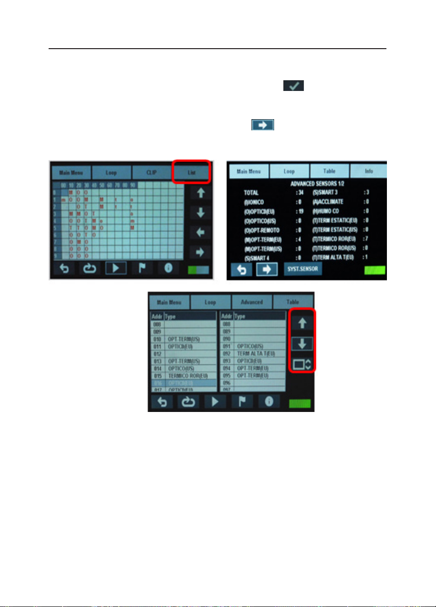
For each sampling POL-200-TS idenes the changes that have occurred since the previous sam-
pling, for that, the type of ID that idenes each address will appear in red or black. The red
color indicates that a change has occurred.
To get more details about each of the elements, select them by clicking directly on them or with
the help of the cursors and mark them by pressing the buon . Holding down this buon
you will get the details of the selected item within the sampling table.
The PWs value is for Honeywell technical team references, PW1 should be around 150 +/- 10%
in Honeywell and Morley while around 300 +/- 10% for Noer / System Sensor. Other values
outside these range should be reported to Honeywell technical support for advice.
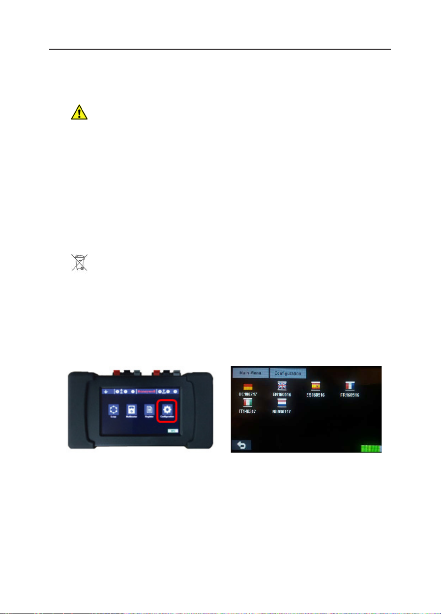
To select between CLIP and ADVANCED Protocol please access the conguraon screen and in
the buon line select one of the two protocols available.

POL-200-TS User Manual
10/16
Select one of the items within the sampling table with the help of the arrows (arrows in the right
margin of the screen) or by clicking on the screen. Press the buon to access the advanced
user informaon screen.
From the self-programming menu and pressing the “List” buon, the user can display a summa-
ry of installed elements. Clicking once more on the icon you will have access to a more
detailed list of the devices of the loop, use the scroll keys located in the right side of the screen
to move of 1 in 1 or in blocks of 10.

POL-200-TS User Manual
11/16
Note 1: For having the right mapping is required that the ISO terminals are properly wired and
the devices support Advanced Protocol.
Note 2: The device like the View FSL-751 or Pinnacle are only answering in CLIP so do not include
an isolator to be acvated from the POL-200-TS.
5. Map
6. Events Recording
To visually verify the wiring map of the loop you
must follow the following instrucons:
In case the installer has correctly wired the isola-
tors using the +IN, +OUT terminals in the B501AP
or in the module terminals the POL-200-TS will
acvate the isolator to show in a graphic.
POL -200-TS provides a device map for any of the
protocols, CLIP or Advanced. Given the character-
iscs of each protocol, the informaon obtained
may dier the locaon of each devices
Remember that in CLIP protocol and mul-mod-
ule devices, each input or output occupies one
direcon in the loop. For Advanced protocol
only the main address will be visible.
You can register in a text le the values selected
from the self-programming screen.
Accessing the registraon screen will display 3
registraon opons:
• Only selected items
• Full loop
• Maintenance

POL-200-TS User Manual
12/16
The rst opon requires previously per-
forming a self-programming of the loop
and marking the elements to register.
To do this proceed as previously de-
scribed, select the elements with the
help of the cursors (arrows in the right
margin of the screen) and press the but-
ton .
Once the computers are selected and
the “only selected items” register op-
on is selected, the POL-200-TS will dis-
play the following screen:
Register through the conguraon op-
on only the necessary informaon,
consult with Honeywell’s technical de-
partment or, if in doubt, select all the
opons.
While logging is done, click the back-
space icon to nish capturing data in the
log le.
It is recommended to use a short sam-
pling me for a short period, even a sin-
gle default read for stable loops, extend-
ing the sample me will result in a larger
le size that will reduce the available
space of the machine for future reports.
The maintenance opon will create a
text le with the extension “.MNT” that
can be edited with “notepad” or Word
for later eding.
NOTE. It is recommended that old maintenance and log les be removed from the folder in order
to be able to generate new records.

POL-200-TS User Manual
13/16
7. Conguration
In the conguraon secon, the user can change the date and me of the device in addion to
changing the language.
The lower ‘CLIP’ icon allows you to select the two types of protocols available CLIP used by the
Noer ID50 / 60 and ID3000, HBS XLS80 or Morley DXc or Advanced by the Noer Pearl.
The ‘Change Theme’ buon allows us to change the background of the screen from white to
black and vice versa.
The ‘About’icon will indicate the soware version of the computer, the Flash Format opon
should only be used if indicated by the Honeywell technical department.
The ‘QR’ icon will allow you to access with a Smartphone the latest online version of the com-
puter.

POL-200-TS User Manual
14/16
8. Troubleshooting
In case that this symbol appears in the right low corner a short-circuit between loop pos-
ive and negave is monitored. Please break the loop in secons to idenfy where the
locaon of the short-circuit is.
This symbol is reporng an inverse wiring fault. Please break the loop into secons to iden-
fy in which base the loop negave is incorrectly connected to the loop posive, or vice
versa.
Flashing the screen or the screen goes o:
Check if the baeries loading level are adequate.
Baeries may be damaged, replace.
Device tags disappear or the queson character appears:
Verify that loop condions meet Honeywell’s requirements.
Try replacing the device and check again.
Check for possible noise on the line.
Record the informaon and check the possibility of cycles of inappropriate
behaviour, excessive current, etc.
No devices appear
Verify that you have not selected Ad protocol instead of CLIP
Check that the loop is connected to the input, “IN” of the POL-200-TS device.
There is no data recorded in my * .MNA, * .MNC and / or * .DAT les:
Remove or delete old les, they are taking up the available memory
space.
“h”… lower case: In case that in the auto-learn ALL the devices in the loop are shown with a
lower case leer please check the protocol selected in the Conguraon.
It may be that the selected loop protocol, i.e. Morley, System Sensor or
Honeywell HBS does not match the loop devices.

POL-200-TS User Manual
15/16
9. Technical Characteristics:
The package includes a USB cable type B to connect the unit to a PC to install a new version by
copying it to the root folder in the POL-200-TS unit.
Note. Autonomy. The baeries lifeme will depend on the output (sounder, ash, and strobes)
acvaons, if the baeries are full charged and the installer is using the auto learn funcon the
unit will provide up to 6 hours of autonomy. When the unit is switch of the current is very low
below 250µA so the baeries will remain charge for days, anyway it will be recommended to full
charge the unit before visit the site.
Charge: 0°C to 40°C
Discharge: 0ºC to 50ºC
Storage: -20ºC to 30ºC
Humidity: 65 ± 20%
Power supply: 230 Vac with 12 V charger (included).
Autonomy: >6 h with baterías at 100% charge.
Baeries: 6x AA 1.2V NiMH 2500mAh. Quick charge in 1h.
Screen: 4.2” TFT 480 x 263 pixels (98x56mm) with 66.000 colors.
Keypad: Dynamic capacive touchpad.
Dimensions: 97mm high x 177mm wide x 44mm deep (rubber protectors included).
Color: Black box with rubber protecon in grey color.
Weight: 550g (with baeries).
POL-200-TS has an even power-o that can discharge the baeries if you do not use it for an
extended period of me.
Power ON/OFF buon

POL-200-TS User Manual
16/16
10. CE conformity
This document is a declaraon that the products listed below conform to the essenal protec-
on requirements of the following European Direcves:
• RoHS - Restricons on the Use of Certain Hazardous Substances in Electrical and Electronic
• Equipment Direcve 2011/65/EU
• Compliance with RoHS 2 - Product does not contain any hazardous substances above the
limits designated in the RoHS Direcve. Product falls within Category 9 - Monitoring and
Control lnstruments
• The EMC Direcve 2014/30/EU, by the applicaon of the following EMC Standards:
• EN 61000-6-3:2007 +A1: 2011 (Emissions)
• Electromagnec compability (EMC) Generic emission standard for residenal,
commercial and light industrial environments.
• EN 50130-4: 2011 +A1: 2014 (lmmunity)
• EMC Product family standard: lmmunity requirements for components of re, in-
truder and social alarm systems

Honeywell Life Safety Iberia
C/Pau Vila 15-19
08911 Badalona
Barcelona, Spain
Tel.: 93 497 39 60 Fax: 93 465 86 35
www.honeywelllifesafety.es
POL-200-TS Diagnosc tool
Ref. doc.: MN-DT-963_EN
20/06/17
© 2017 Honeywell International Inc.
Other manuals for POL-200-TS
1
Table of contents
Other Honeywell Test Equipment manuals

Honeywell
Honeywell HPBLT Technical manual

Honeywell
Honeywell Posi3 USB User manual

Honeywell
Honeywell Vibrex 2000 User manual

Honeywell
Honeywell MicroDock II User manual

Honeywell
Honeywell TESTAIR 4 User manual

Honeywell
Honeywell Enraf VITO 762 User manual

Honeywell
Honeywell TB7200 Series User manual

Honeywell
Honeywell BW MicroDock II User manual

Honeywell
Honeywell S300RPTU User manual

Honeywell
Honeywell Posi 3 User manual