Page 3 of 11 P/N 13-395 11/4/20 Rev.05
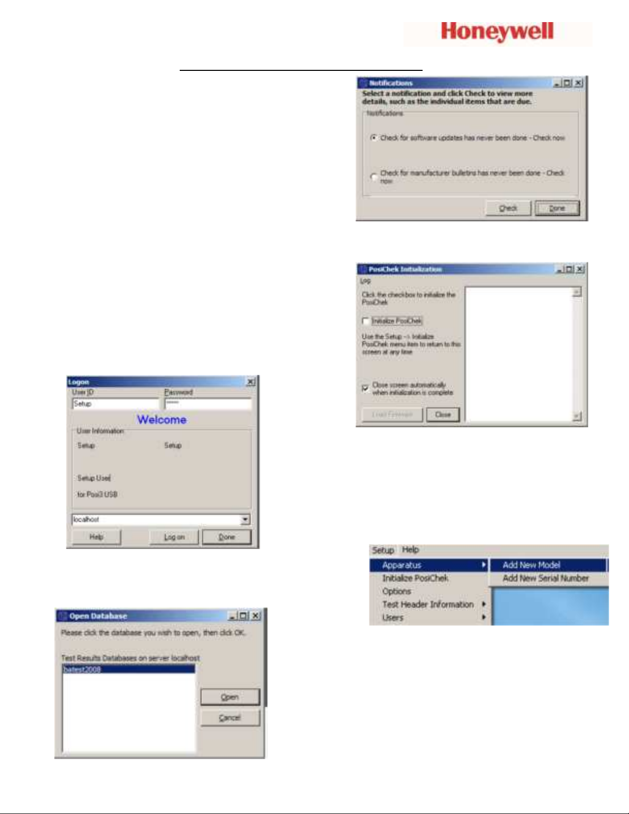
7.
Type in a name for the test results database (Special
characters and spaces are not allowed). Click OK.
8.
Click the Finish button to exit the Database
Installation Wizard.
9.
For Windows 7 or above, restarting the PC is
optional.
Advanced Software Installation
All POSI3 USB software end users must have
permission to modify the following areas of the PC:
1.
The registry section
HKEY_LOCAL_MACHINE\SOFTWARE\Sperian\Pos
i3
USB and all its subsections.
2.
The folder location C:\Program
Files\Sperian\Posi3USB and all its subfolders.
It may be necessary to contact your IT department so
they can provide you with the necessary access.
Note on Brand-Specific Software: If you are planning to service a
specific brand of SCBA, make sure you have the OEM Posi3 USB
software for that brand.
1.
To install your POSI3 USB software, if having a
CD, insert the CD-ROM. If the software fails to
launch automatically, use Windows Explorer to
navigate to the CD-ROM drive and run
BATestSetup.exe. If having a downloaded file, be
sure to have the BATestSetup.exe and the
License.exe applications in the same folder.
2.
It is recommended to exit any other Windows
programs that may be running and verify the
License information and End User License
Agreement.
3.
By default, the software is installed to
C:\Program Files
(x86)\Sperian\Posi3USB\Standard\BATest.
4.
Follow the screen prompts to continue installation
with default settings.
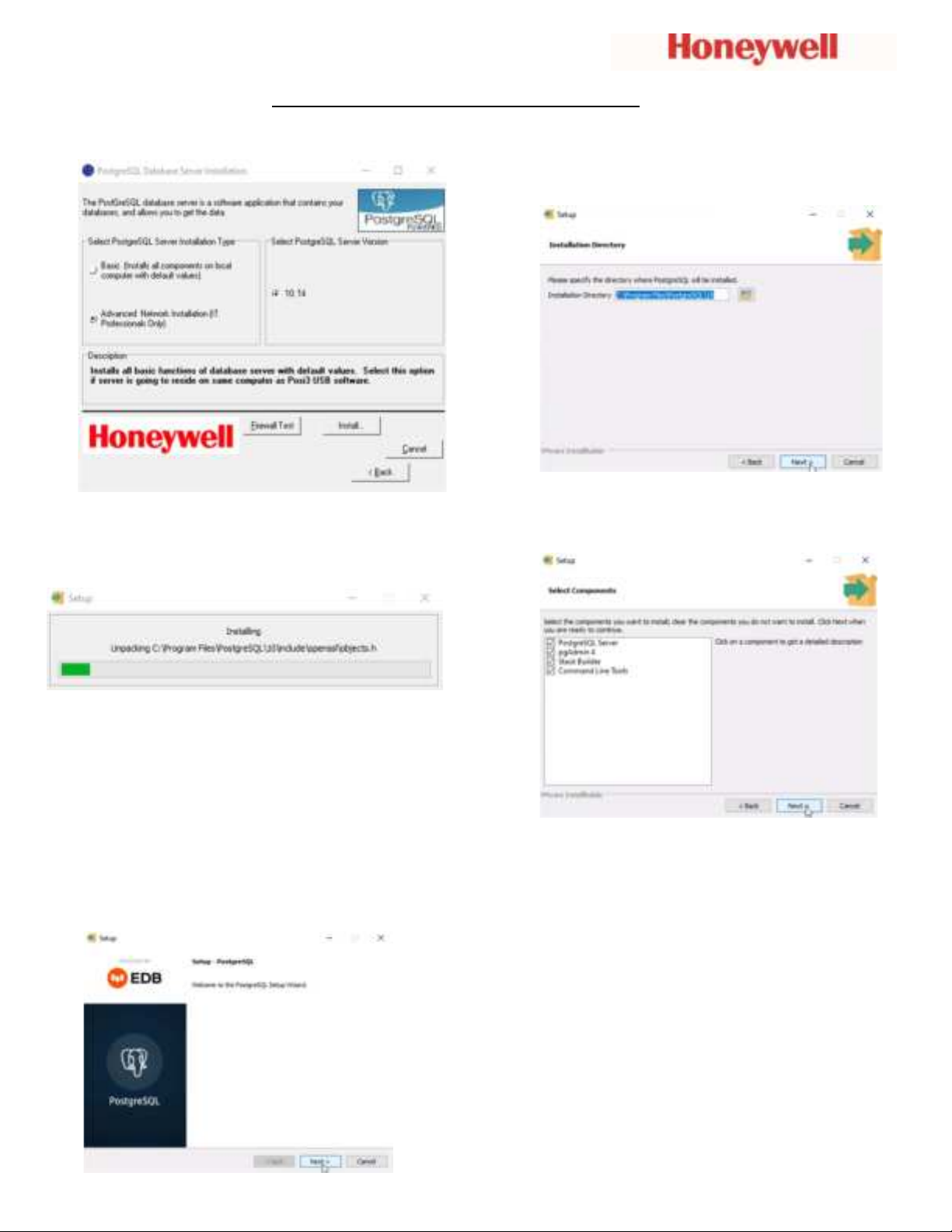
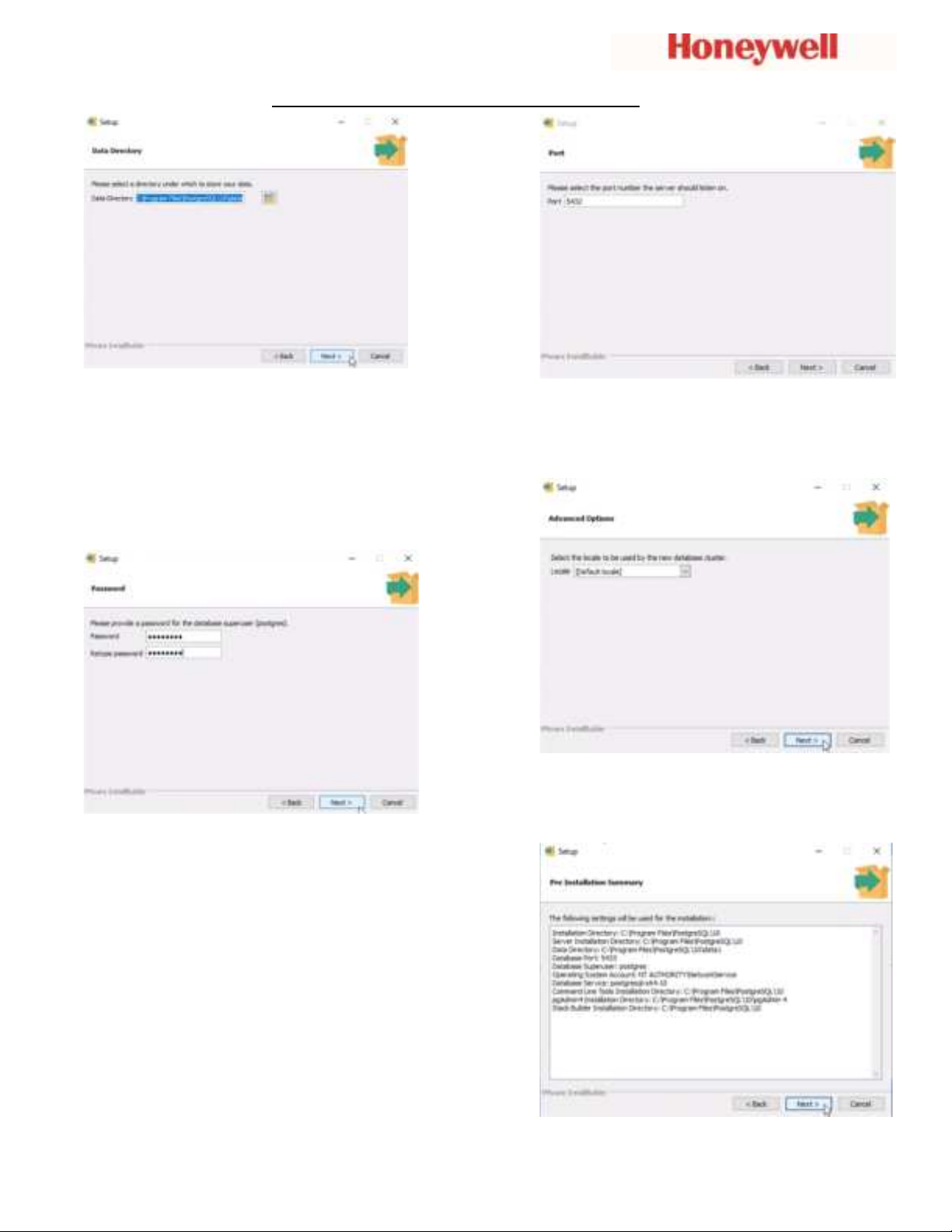
Database Setup
The Database Installation Wizard is automatically
launched near the end of the software installation.
1.
First time installation requires the installation
of the PostgreSQL Server.
(For advanced installation or connecting to an
existing server, please refer to the included Setup
Guide or Help File by pressing F1 at any time)
Note: Administrator-level system access is
required to install the PostgreSQL database
server.
In some versions of Windows, you may need to
click “OK” to proceed.