manuals.online logo
Brands
  1. Home
  2. •
  3. Brands
  4. •
  5. Honeywell
  6. •
  7. Transmitter
  8. •
  9. Honeywell ADEMCO 5820L Assembly instructions

Honeywell ADEMCO 5820L Assembly instructions

Ademco
K9230V3
5820L Exterior of box
File: K9230V3_Blueline_Ademco_5820L_instruct_exterior.eps
ASSEMBLED IN MEXICO
© 2009 Honeywell International Inc.
All Rights Reserved
Long Life Battery Included
ADEMCO 5820L
See inside of carton for
Installation Instructions Slim Line Transmitter
Slim Line Transmitter
ADEMCO 5820L
Slim Line Transmitter
7/11 K9230V3
ADEMCO 5820L
Slim Line Transmitter
ADEMCO 5820L
<<< Open Carton Along Perforations >>>
Perforation (1/4" x 1/8")
Ideal for casement and
double hung windows
R
R
LITHIUM
LITHIUM
ADEMCO 5820L
Slim Line Transmitter
FEDERAL COMMUNICATIONS
COMMISSION STATEMENTS:
The user shall not make any
changes or modifications to the
equipment unless authorized by the
Installation Instructions or User's
Manual. Unauthorized changes or
modifications could void the user's
authority to operate the equipment.
+
MOUNTING
HOLE
MOUNTING
HOLE
TAMPER
PROTECTION
BATTERY
(1.5VDC, AAA
LITHIUM.
SEE NOTE
INSIDE.)
TAMPER
SWITCH
Sleek design is nearly half the size of competitors
Easy to open case requires no special tools
Case tamper protection (front and back)
Ideal for double-hung windows
Easy replaceable AAA lithium battery
Sleek design is nearly half the size of competitors
Easy to open case requires no special tools
Case tamper protection (front and back)
Ideal for double-hung windows
Easy replaceable AAA lithium battery
Front and back-case tamper is
provided using the same switch.
The front-case tamper is always
enabled. Adding the third screw
as shown in the figure enables
the back-case tamper.
Tamper Protection
N219
ÊK9230V3HŠ
Ademco
K9230V3
5820L Interior of box
File: K9230V3_Blueline_Ademco_5820L_instruct_interior.eps
Battery Information
NOTE
FOR DOCUMENTATION AND ONLINE SUPPORT
http://www.security.honeywell.com/hsc/resources/MyWebTech
FOR WARRANTY INFORMATION GO TO:
http://www.security.honeywell.com/hsc/resources/wa
See inside of
carton for
installation
instructions.
See inside of
carton for
installation
instructions.
REFER TO THE INSTALLATION
INSTRUCTIONS FOR THE CONTROL
WITH WHICH THIS DEVICE IS USED,
FOR DETAILS REGARDING
LIMITATIONS OF THE ENTIRE
ALARM SYSTEM.
1.
2.
3.
5820L is a single-zone Slim-Line
Door/Window contact transmitter
that provides wireless notification
of intrusion.
Install mounting screws
in the two outside
mounting holes as
shown in the diagram
using a #1 Phillips.
If the case-back tamper
switch will be used,
install a third screw in
the middle hole.
Mount the magnet
(supplied) adjacent to
the two vertical
positioning lines on the
case side (see diagram).
The gap can be one-half
of an inch maximum.
To reinstall the cover,
position the cover so
that it covers the
mounted case-back, and
snap-shut. The two case
halves can only be fitted
together in one direction.
Temporarily mount the 5820L
and magnet using the double-
back tape provided.
If the Go/No Go test was
successful, remove the
transmitters cover by inserting
the flat blade of a small screw-
driver into the opening slot at
one end of the unit as shown
in the diagram and separate the
two halves.
The 5820L must only be
mounted against a flat surface.
A curved surface would cause
undo stress to the unit and
possible failure to operate
properly.
4.
5.
6.
7.
Before mounting permanently
using the double-back tape or
mounting screws, conduct a
Go/No Go test to verify adequate
signal strength and reorient or
relocate the transmitter if necessary
NOTE
Installation
Alkaline Battery Will Yield Less
Battery Life than Lithium
Replace battery only with:
Energizer L92 AAALithium or
AAAAlkaline, Duracell MX2400,
PanasonicAM-4PI,
Eveready Engeriger EN92.
BATTERY CAUTION: Risk of fire,
explosion and burns. Do not
recharge, disassemble, heat above
212 F (100 C) or incinerate.
Dispose of used batteries properly.
Keep away from children.
Perforation (1/4 x 1/8)
MAGNET
OPENING
SLOT
GAP
0.5" MAX
MAGNET ALIGNMENT
LOCATORS
Do NOT attempt to remove
the PCB from the plastic
cover for any reason.
NOTE
During the programming of the
control panel transmitter must be
enrolled as Input Type 3,
Supervised RF), Loop 1.
NOTE
Observe correct polarity.
FCC / IC Statement:
This device complies with Part 15
of the FCC Rules, and RSS 210 of
IC.Operation is subject to the
following two conditions: (1) This
device may not cause harmful
interference (2)This device must
accept any interference received,
including interference that may
cause undesired operation.
Cet appareil est conforme à la
partie 15 des règles de la FCC &
de RSS 210 des Industries
Canada. Son fonctionnement est
soumis aux conditions suivantes:
(1) Cet appareil ne doit pas causer
d' interferences nuisibles.(2) Cet
appareil doit accepter toute
interference reçue y compris les
interferences causant une
reception indésirable.
K9232V2 7/11 Rev. A
ADEMCO 5820L
Door/Window Contact Transmitter
Door/Window Contact TransmitterDoor/Window Contact Transmitter
Door/Window Contact Transmitter
INSTALLATION AND SETUP GUIDE
GENERAL INFORMATION
The 5820L is a single-zone Slim-Line Door/Window
contact transmitter that provides wireless
notification of intrusion. The 5820L can be used
only with alarm systems that support 5800 Series
wireless devices. The 5820L has its own unique
serial number permanently assigned during
manufacture. You must enroll the transmitter’s
serial number in the control panel before it will
operate in the system. Refer to the control panel’s
installation instructions for programming details.
Note:
During programming of the control panel,
5820L transmitters must be enrolled as Input Type
3 (Supervised RF), Loop 1.
The transmitter is powered by one AAA Lithium (or
alkaline) battery that is easily replaced when a low
battery condition is indicated by the control panel.
TAMPER PROTECTION
Front and back-case tamper is provided using the
same switch. The front-case tamper is always
enabled. Adding the third screw as shown in Figure
2 enables the back-case tamper.
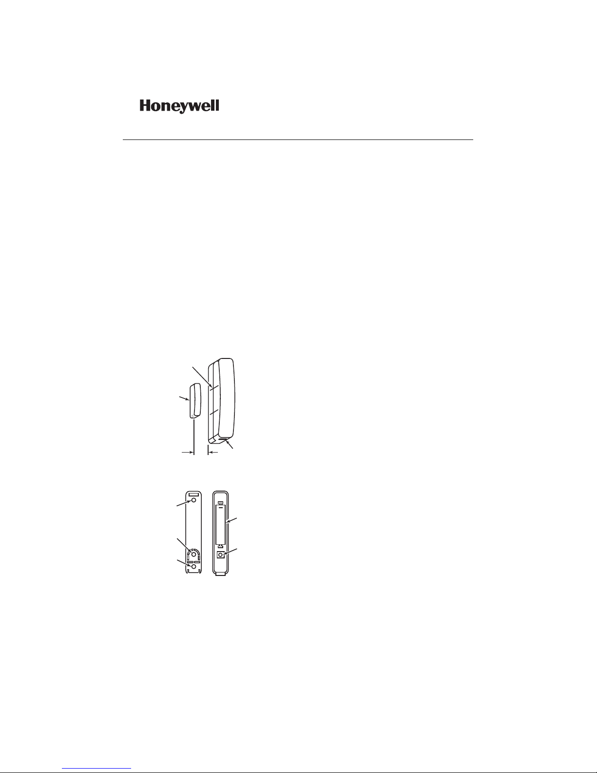
MAGNET
OPENING
SLOT
GAP
0.5" MAX
5820-001-V0
MAGNET ALIGNMENT
LOCATORS
Figure 1. 5820L (Typical Installation Arrangement)
+
MOUNTING
HOLE
MOUNTING
HOLE
TAMPER
PROTECTION
5820-002-V1
BATTERY
(1.5VDC, AAA
LITHIUM OR
ALKALINE)
TAMPER
SWITCH
Figure 2. 5820L Mounting/Battery Location
MOUNTING
The description that follows assumes that the
transmitter will be mounted as shown in Figure 1,
with the magnet located adjacent to the unit's left
side. The transmitter may, however, be installed in
any direction, as long as the relationship of the unit
to the magnet is maintained as shown in Figure 1.
1. Temporarily mount the 5820L and magnet
using the double-back tape supplied.
Note:
Before mounting the transmitter and magnet
permanently using the double-back tape or
mounting screws, conduct a Go/No Go test (see
control's instructions) to verify adequate signal
strength and reorient or relocate the transmitter if
necessary.
2. If the Go/No Go test was successful, remove
the transmitter's cover by inserting the flat
blade of a small screwdriver into the opening
slot at one end of the unit as shown in Figure 1,
and separating the two halves.
3. The 5820L must only be mounted against a flat
surface. A curved surface would cause undue
stress to the unit and possible failure to operate
properly.
4. Install mounting screws in the two outside
mounting holes as shown in Figure 2 using a #1
Phillips.
5. If the case-back tamper switch will be used,
install a third screw in the middle hole.
6. Mount the magnet (supplied) adjacent to the
two vertical positioning lines on the case side
(see Figure 1). The gap can be one-half an inch
maximum.
7. To reinstall the cover, position the cover so
that it covers the mounted case-back, and snap-
shut. The two case halves can only be fitted
together in one direction.
Note:
Do NOT attempt to remove the PCB from the
plastic cover for any reason.
BATTERY
INSTALLATION/REPLACEMENT
Replace battery only with same or equivalent type.
Dispose of used batteries according to the battery
manufacturer’s instruction.
1. Remove the transmitter's cover (if it is not
off already) as described in Mounting; step 2.
2. Observe correct polarity and insert the
battery provided into the battery retainer clips
as shown in Figure 2.
Note:Replace battery only with type specified in
the Specifications paragraph.
SPECIFICATIONS
Dimensions: ...................... 3.0” H x 0.5” W x 0.8” D
76.2mm x 12.7mm x 20.3mm
Battery: ...... 1.5VDC, AAA Lithium (Energizer L92) or
AAA Alkaline, (Duracell MX2400,
Panasonic AM-4PI, Eveready Energizer
EN92)
Gap: ......................................... 0.5 inch maximum
Magnet: ...........................WA5816MAG (supplied)
BATTERY CAUTION: Risk of fire, explosion
and burns. Do not recharge, disassemble, heat
above 212° F (100° C) or incinerate. Dispose of
used batteries properly. Keep away from
children.
FCC / IC STATEMENT
This device complies with Part 15 of the FCC Rules and RSS210 of Industry Canada. Operation is
subject to the following two conditions: (1) This device may not cause harmful interference, and (2),
this device must accept any interference received, including interference that may cause undesired
operation.
Cet appareil est conforme à la partie 15 des règles de la FCC & de RSS 210 des Industries
Canada. Son fonctionnement est soumis aux conditions suivantes: (1) Cet appareil ne doit pas
causer d' interferences nuisibles. (2) Cet appareil doit accepter toute interference reçue y compris
les interferences causant une reception indésirable.
FEDERAL COMMUNICATIONS COMMISSION STATEMENT:
The user shall not make any changes or modifications to the equipment unless authorized by the
Installation Instructions or User's Manual.
Unauthorized changes or modifications could void the user's authority to operate the equipment.
For the latest warranty information, please go to:
http://www.security.honeywell.com/hsc/resources/wa
ÊK9232V2KŠ
K9232V2 7/11 Rev. A
2 Corporate Center Drive, Suite 100
P.O. Box 9040, Melville, NY 11747
Copyright2008
Honeywell International Inc.
http://www.honeywell.com/security

Other Honeywell Transmitter manuals

Honeywell oneWireless XYR 6000 User manual

Honeywell

Honeywell oneWireless XYR 6000 User manual

Honeywell ST 3000 User manual

Honeywell

Honeywell ST 3000 User manual

Honeywell 5800MICRA User manual

Honeywell

Honeywell 5800MICRA User manual

Honeywell ST 3000 User manual

Honeywell

Honeywell ST 3000 User manual

Honeywell 5894PI - Ademco Wireless PIR Motion Sensor User manual

Honeywell

Honeywell 5894PI - Ademco Wireless PIR Motion Sensor User manual

Honeywell SMV 3000 User manual

Honeywell

Honeywell SMV 3000 User manual

Honeywell ADEMCO 5817 Assembly instructions

Honeywell

Honeywell ADEMCO 5817 Assembly instructions

Honeywell Fema Moduflex F Series Manual

Honeywell

Honeywell Fema Moduflex F Series Manual

Honeywell NOTIFIER UDACT-2 User manual

Honeywell

Honeywell NOTIFIER UDACT-2 User manual

Honeywell OELD User manual

Honeywell

Honeywell OELD User manual

Honeywell 5820L - Slim Line Wireless Door/Window... Assembly instructions

Honeywell

Honeywell 5820L - Slim Line Wireless Door/Window... Assembly instructions

Honeywell SLN 700 User manual

Honeywell

Honeywell SLN 700 User manual

Honeywell ST 3000 Installation and operating instructions

Honeywell

Honeywell ST 3000 Installation and operating instructions

Honeywell 5878 Assembly instructions

Honeywell

Honeywell 5878 Assembly instructions

Honeywell XNX User manual

Honeywell

Honeywell XNX User manual

Honeywell SmartLine STIW400 User manual

Honeywell

Honeywell SmartLine STIW400 User manual

Honeywell ADEMCO 5805-6 User manual

Honeywell

Honeywell ADEMCO 5805-6 User manual

Honeywell ST 800 Series User manual

Honeywell

Honeywell ST 800 Series User manual

Honeywell STT700 SmartLine User guide

Honeywell

Honeywell STT700 SmartLine User guide

Honeywell ADEMCO 5878 Assembly instructions

Honeywell

Honeywell ADEMCO 5878 Assembly instructions

Honeywell oneWireless XYR 6000 User manual

Honeywell

Honeywell oneWireless XYR 6000 User manual

Honeywell SMV800 Instruction Manual

Honeywell

Honeywell SMV800 Instruction Manual

Honeywell STT25D User manual

Honeywell

Honeywell STT25D User manual

Honeywell ADEMCO 5804 Assembly instructions

Honeywell

Honeywell ADEMCO 5804 Assembly instructions

Popular Transmitter manuals by other brands

Bioness StimRouter User's Reference Card

Bioness

Bioness StimRouter User's Reference Card

Becker Centronic EasyControl EC541-II Assembly and operating instructions

Becker

Becker Centronic EasyControl EC541-II Assembly and operating instructions

AVGear AVG-HDWP70HD user manual

AVGear

AVGear AVG-HDWP70HD user manual

FISCHER DE43 operating manual

FISCHER

FISCHER DE43 operating manual

ASTEL TTR 202 operating instructions

ASTEL

ASTEL TTR 202 operating instructions

Pavone Systems DAT 1400 Technical manual

Pavone Systems

Pavone Systems DAT 1400 Technical manual

Marmitek Audio Anywhere 625 user manual

Marmitek

Marmitek Audio Anywhere 625 user manual

Dräger VarioGard IR EX Instructions for use

Dräger

Dräger VarioGard IR EX Instructions for use

SONBEST SM2101M user manual

SONBEST

SONBEST SM2101M user manual

Novus NP600 instruction manual

Novus

Novus NP600 instruction manual

JETI model Central box 310 user manual

JETI model

JETI model Central box 310 user manual

JUMO 404304 Series operating instructions

JUMO

JUMO 404304 Series operating instructions

Wilkerson Instrument DR4302 Series instructions

Wilkerson Instrument

Wilkerson Instrument DR4302 Series instructions

E+E Elektronik EE360 Operation manual

E+E Elektronik

E+E Elektronik EE360 Operation manual

Evikon E2618-NH3 user manual

Evikon

Evikon E2618-NH3 user manual

Salus RT510SPE installation guide

Salus

Salus RT510SPE installation guide

Niko 410-00001 manual

Niko

Niko 410-00001 manual

Cisco Prisma II HD-LRMW Installation and operation guide

Cisco

Cisco Prisma II HD-LRMW Installation and operation guide

manuals.online logo
manuals.online logoBrands
  • About & Mission
  • Contact us
  • Privacy Policy
  • Terms and Conditions

Copyright 2025 Manuals.Online. All Rights Reserved.