Honeywell ADEMCO 5869 User manual
Other Honeywell Transmitter manuals
Honeywell
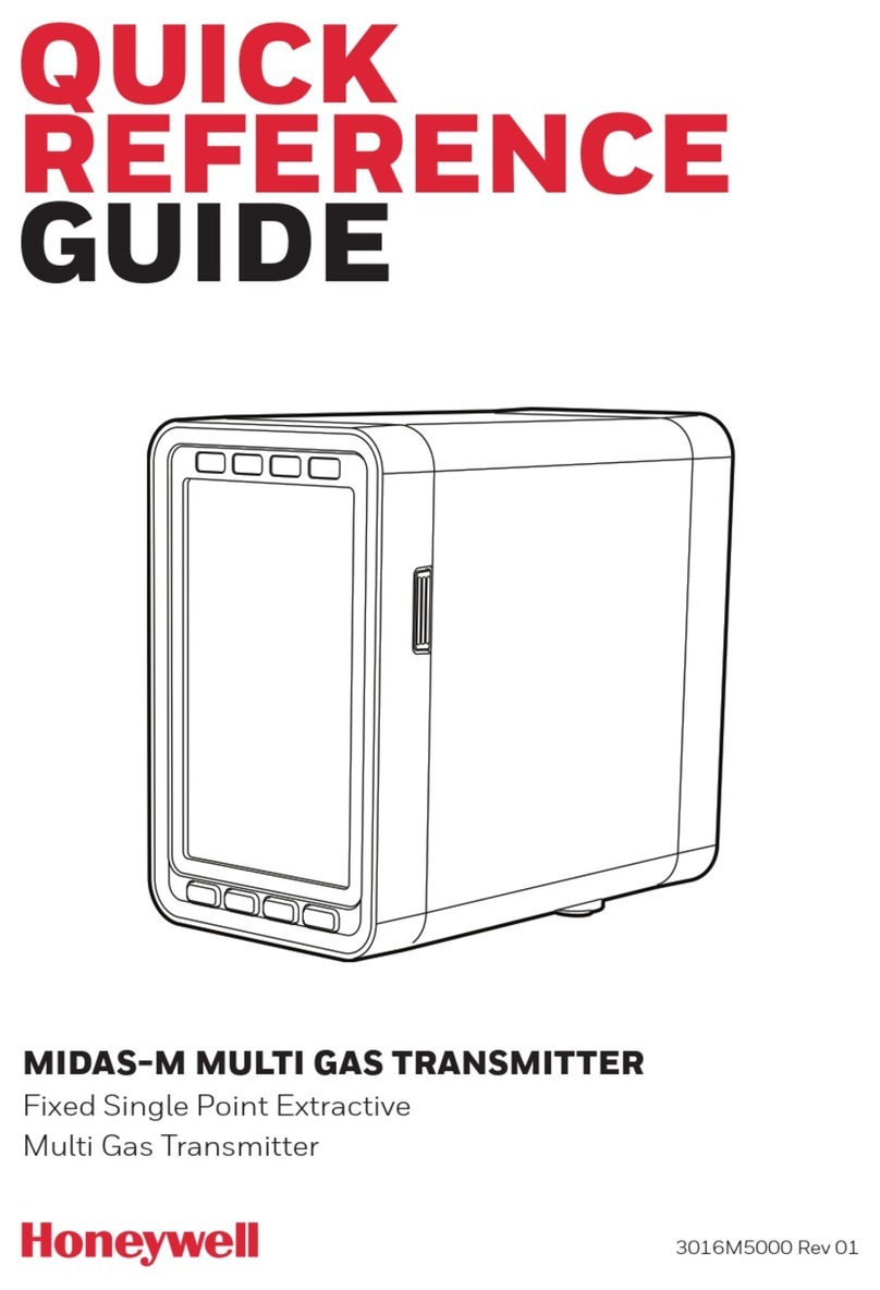
Honeywell Midas-M User manual
Honeywell
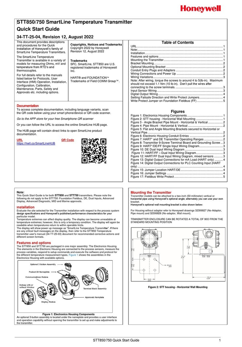
Honeywell STT850 SMARTLINE User manual

Honeywell
Honeywell SmartLine ST700 User manual

Honeywell
Honeywell OELD User manual
Honeywell
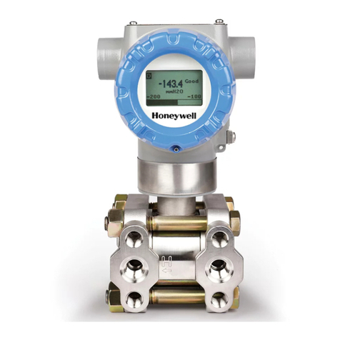
Honeywell ST 800 Series User manual

Honeywell
Honeywell 5834-4EN User manual
Honeywell
Honeywell SMV800 User manual
Honeywell
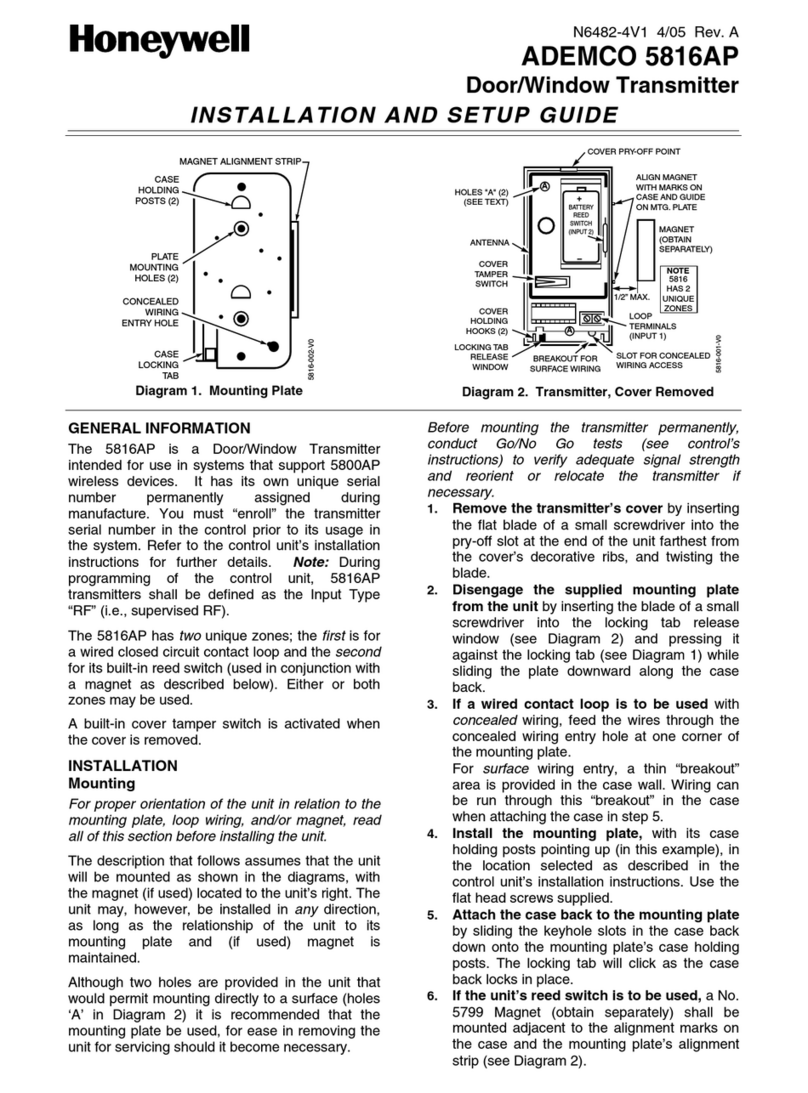
Honeywell ADEMCO 5816AP Assembly instructions
Honeywell
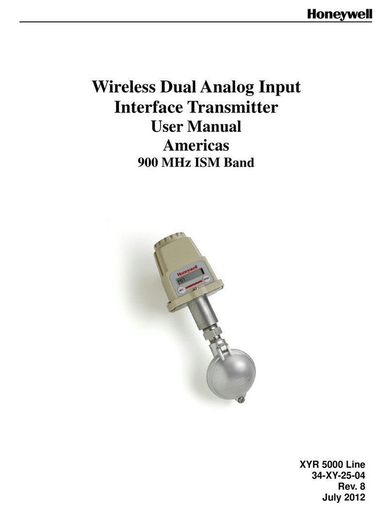
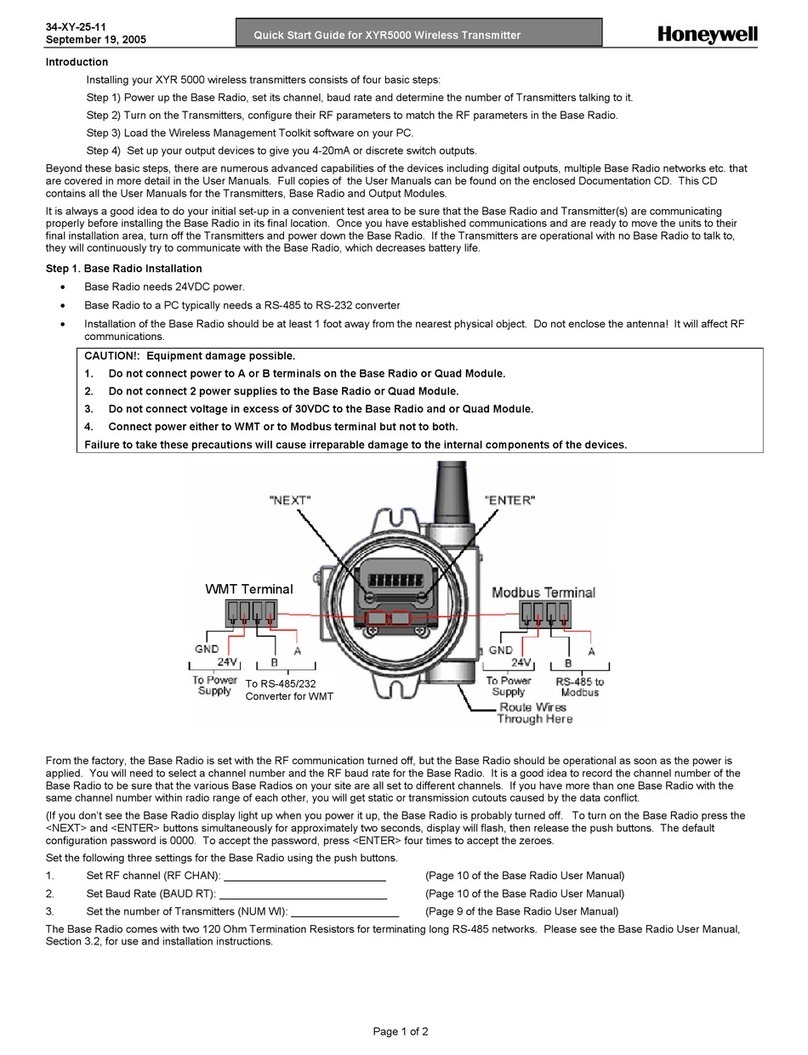
Honeywell XYR 5000 Series User manual

Honeywell
Honeywell Satellite XT 9602-0400 FTT User manual
Honeywell
Honeywell SMV 3000 User manual
Honeywell
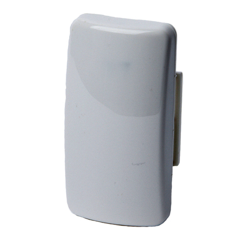
Honeywell 5815 - Ademco - Wireless Door User manual
Honeywell
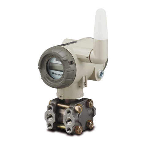
Honeywell oneWireless XYR 6000 User manual

Honeywell
Honeywell STT700 STT700 User manual
Honeywell
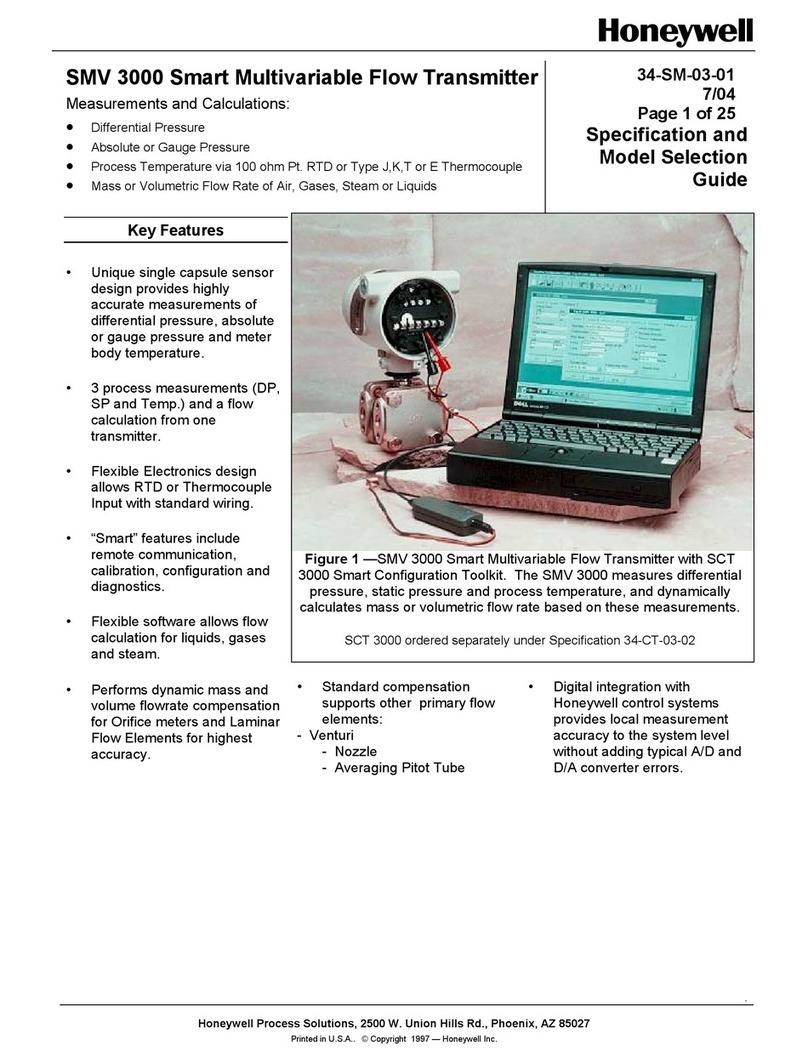
Honeywell SMV 3000 User manual

Honeywell
Honeywell ADEMCO 5878 Assembly instructions
Honeywell
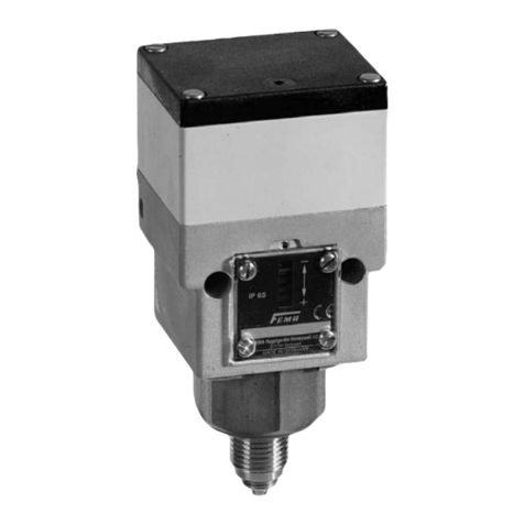
Honeywell Fema Moduflex F Series Manual

Honeywell
Honeywell SMV800 User manual

Honeywell
Honeywell SmartLine User manual
Honeywell
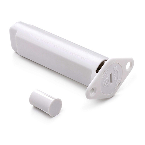
Honeywell ADEMCO 5818MNL Assembly instructions
Popular Transmitter manuals by other brands

Rosemount
Rosemount 4600 Reference manual

Speaka Professional
Speaka Professional 2342740 operating instructions

trubomat
trubomat GAB 1000 instruction manual

Teledyne Analytical Instruments
Teledyne Analytical Instruments LXT-380 instructions

Rondish
Rondish UT-11 quick start guide

MG
MG 10JRE instruction manual
