Tables
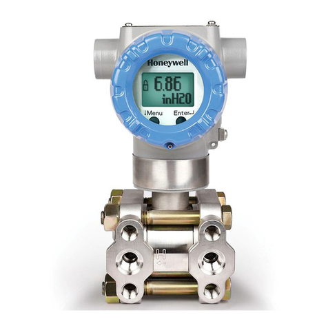
10/05 ST 3000 HART Transmitter Release 300 User Manual
ix
Tables
Table 1 ST 3000 Pressure Transmitter Family ..............................................................................................................5
Table 2 Local Smart Meter Options ............................................................................................................................10
Table 3 Start-up Tasks Reference................................................................................................................................12
Table 4 Operating Temperature Limits (Transmitters with Silicone Fill Fluid DC200) .............................................15
Table 5 Transmitter Maximum Allowable Working Pressure (MAWP) Ratings........................................................16
Table 6 Mounting ST 3000 Transmitter to a Bracket ..................................................................................................18
Table 7 Zero Corrects Procedure for Transmitters with a Small Differential Pressure Span ......................................21
Table 8 Flush Mount Transmitter Installation .............................................................................................................24
Table 9 Mounting Remote Diaphragm Seal Transmitter.............................................................................................26
Table 10 Suggested Transmitter Location for Given Processes ..................................................................................29
Table 11 Process Connections.....................................................................................................................................30
Table 12 Flange Description........................................................................................................................................31
Table 13 Installing Flange Adapter .............................................................................................................................32
Table 14 Wiring the Transmitter .................................................................................................................................35
Table 15 Starting Communications with Transmitter..................................................................................................41
Table 16 Reviewing Factory-Set Configuration Parameters .......................................................................................42
Table 17 Summary of Pressure Transmitter Configuration Parameters ......................................................................48
Table 18 Entering Tag Number ...................................................................................................................................55
Table 19 Selecting Engineering Units .........................................................................................................................56
Table 20 Keying in LRV and URV .............................................................................................................................57
Table 21 Setting LRV and URV to Applied Pressures................................................................................................58
Table 22 Viewing/Entering Device Information Data.................................................................................................59
Table 23 Selecting Output Conformity........................................................................................................................60
Table 24 Adjusting Damping Time .............................................................................................................................62
Table 25 Selecting SV Temperature Units ..................................................................................................................63
Table 26 Selecting Poll Address..................................................................................................................................64
Table 27 Start-up Procedure Reference .......................................................................................................................66
Table 28 Using Transmitter in Constant-Current Source (Output) Mode ...................................................................67
Table 29 Starting Up DP Transmitter for Flow Measurement.....................................................................................69
Table 30 Starting Up DP Transmitter for Pressure Measurement ...............................................................................71
Table 31 Starting Up DP Transmitter for Liquid Level Measurement in Vented Tank...............................................73
Table 32 Starting Up DP Transmitter for Liquid Level Measurement in Pressurized Tank........................................76
Table 33 Starting Up GP Transmitter for Pressure or Liquid Level Measurement .....................................................79
Table 34 Starting Up AP Transmitter for Pressure Measurement. ..............................................................................82
Table 35 Starting Up DP Transmitter with Remote Seals for Liquid Level Measurement .........................................83
Table 36 Summary of Keystrokes for Operation Data Access ....................................................................................88
Table 37 Changing Default Failsafe Direction or Write Protect Jumper.....................................................................91
Table 38 Writing Data in the Message Area................................................................................................................92
Table 39 Saving a Configuration Database .................................................................................................................94
Table 40 Downloading a Configuration Database.......................................................................................................95
Table 41 Inspecting and Cleaning Barrier Diaphragms.............................................................................................100
Table 42 Process Head Bolt Torque Ratings .............................................................................................................102
Table 43 Replacing PWA ..........................................................................................................................................102
Table 44 Replacing Meter Body Only.......................................................................................................................105
Table 45 Calibrating Output Signal for Transmitter in Analog Mode.......................................................................110
Table 46 Calibrating Measurement Range ................................................................................................................111
Table 47 Resetting Calibration Data..........................................................................................................................113
Table 48 Summary of Diagnostic Messages for Critical Failures .............................................................................116
Table 49 Summary of Diagnostic Messages for Non-Critical Failures .....................................................................117
Table 50 Summary of Diagnostic Messages for Communication Errors...................................................................117
Table 51 Diagnostic Message Interpretation Table ...................................................................................................118
Table 52 Resetting the Transmitter............................................................................................................................120


