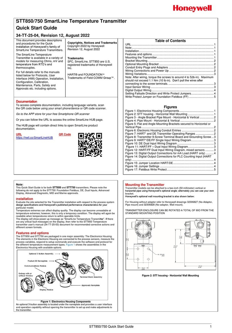
SmartLine Temperature Transmitter
2 Quick Start Installation Guide
Table of Contents
Installation.................................................................................................................... 3
Features and options.................................................................................................... 3
Mounting the Transmitter ............................................................................................. 4
Bracket Mounting..................................................................................................5
Optional Mounting Bracket....................................................................................6
Conduit Entry Plugs and Adapters...............................................................................7
Wiring Connections and Power Up...............................................................................8
Wiring Variations.................................................................................................10
Input Sensor Wiring............................................................................................. 10
Explosion-Proof Conduit Seal .................................................................................... 11
Set the Jumpers For HART........................................................................................ 12
Setting Failsafe Direction and Write Protect Jumpers.........................................12
Configuration Guide ...................................................................................................14
Tables
Table 1 - Jumper Settings..........................................................................................13
Table 2 –Available Display Characteristics ...............................................................14
Table 3 –Basic Display Configuration........................................................................14
Figures
Figure 1 –Electronics Housing Components ............................................................... 3
Figure 2 –STT750 with adapter housing - Horizontal Wall Mounting...........................4
Figure 3 –STT750 Pipe Mount, Vertical ......................................................................4
Figure 4 –STT750 Pipe Mount with adapter housing - Horizontal & Vertical...............5
Figure 5: Flat and Angle Mounting Brackets secured to Horizontal or Vertical Pipe ....6
Figure 6: Electronic Housing Conduit Entries............................................................... 7
Figure 7: STT750 HART/DE Transmitter Operating Ranges........................................ 8
Figure 8: Transmitter 9-Screw Terminal Board and Grounding Screw......................... 9
Figure 9 –STT750 Thermocouple, RTD, mV, Ohm and Volt Connections................ 10
Figure 10: Jumper Location HART............................................................................13
