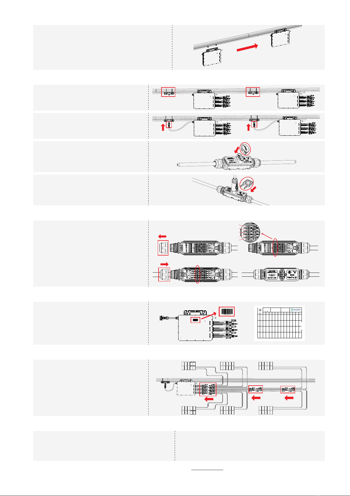
Step 2. Complete the AC Connection
A ) Attach the 3P-AC Bus Cable with the
mounting rail, and fix the cable by tie wraps.
B ) Push the AC connector from microinverter
to the 3P-AC bus connector until you hear
“click”.
C ) If any bus port is vacant, please plug the
3P-AC sub cap into the port to protect it
from dust and walter.
Note: Under the circumstance that need to remove the
inverter AC cable from 3P-AC bus connector,
please use the 3P-AC connector unlock tool and
insert the tool into the side of AC port to remove.
Step 3. Install AC End Cable
A ) Prepare the 3P-AC End Cable with the proper
length, insert one side of the cable into the seal
nut. Match the L1, L2, L3, N and Ground line into
the slot accordingly. Tighten the screws, and then
tighten the cap back to the connector. Plug the
upper cover back to the 3P-AC bus connector.
B ) Connect the other side of the AC End Cable to
the distribution box, and wire it to the local grid
network.
Step 5. Connect PV Modules
A ) Mount the PV modules above the micro-
inverter
B ) Connect the PV modules’ DC cables to the
DC input side of the microinverter.
Step 6. Energize the System Step 7. Monitoring System Set Up
A )
B )
Turn on the AC breaker for the branch circuit.
Turn on the main AC breaker for the house. The system
will start to generate power after several minutes.
Refer to the DTU User Manual or DTU Quick Install Guide,
and Quick Installation Guide for HMP Online Registration
to install the DTU and set up monitoring system.
Step 4. Create an Installation Map
A ) Peel the removable serial number label from
each microinverter (shown as picture).
B ) Affix the serial number label to the respec-
tive location on the installation map
C ) Hang the microinverter on the screw (shown as picture ),
and tighten the screw. The silver cover side of the
microinverter should be facing the panel.
Note: Install the microinverter with the silver side up and under the
PV module. Allow a minimum of 2cm around the micro-
inverter enclosure to ensure ventilation and heat dissipation.
Tosheet ______
Tosheet ______ AP040228 REV1.1
Panel Group:
Azimuth:
Tilt:
Sheet____of____
Customer Information:
DTU Serial Number:
1 2 3 4 5 6 7 8 9 10 11 12 13 14
A
B
C
D
Tosheet ________
Tosheet ________
© 2020 Hoymiles Power Electronics Inc. All rights reserved. AP040299 REV1.1
Product information is subject to change without notice. (Please download reference manuals at www.hoymiles.com).
N
PE
L3
L2
L1


