manuals.online logo
Brands
  1. Home
  2. •
  3. Brands
  4. •
  5. HP
  6. •
  7. Computer Hardware
  8. •
  9. HP 10512 Installation instructions

HP 10512 Installation instructions

Product End-of-Life Disassembly Instructions
Product Category: Networking Equipment
Marketing Name / Model
[List multiple models if applicable.]
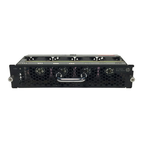
HP 10512 Switch Chassis (JC748A)
HP 10512 TAA Switch Chassis (JG823A)
Purpose: The document is intended for use by end-of-life recyclers or treatment facilities. It provides the basic instructions
for the disassembly of HP products to remove components and materials requiring selective treatment, as defined by EU
directive 2002/96/EC, Waste Electrical and Electronic Equipment (WEEE)
1.0 Items Requiring Selective Treatment
1.1 Items listed below are classified as requiring selective treatment.
1.2 Enter the quantity of items contained within the product which require selective treatment in the right column, as
applicable.
Item Description Notes
Quantity
of items
included
in product
Printed Circuit Boards (PCB) or Printed Circuit
Assemblies (PCA)
With a surface greater than 10 sq cm
7
Batteries
All types including standard alkaline and lithium coin
or button style batteries
5
Mercury-containing components
For example, mercury in lamps, display backlights,
scanner lamps, switches, batteries
0
Liquid Crystal Displays (LCD) with a surface greater
than 100 sq cm
Includes background illuminated displays with gas
discharge lamps
0
Cathode Ray Tubes (CRT)
0
Capacitors / condensers (Containing PCB/PCT)
0
Electrolytic Capacitors / Condensers measuring
greater than 2.5 cm in diameter or height
0
External electrical cables and cords
0
Gas Discharge Lamps
0
Plastics containing Brominated Flame Retardants
weighing > 25 grams (not including PCBs or PCAs
already listed as a separate item above)
12
Components and parts containing toner and ink,
including liquids, semi-liquids (gel/paste) and toner
Include the cartridges, print heads, tubes, vent
chambers, and service stations.
0
Components and waste containing asbestos
0
Components, parts and materials containing
refractory ceramic fibers
0
Components, parts and materials containing
radioactive substances
0
EL-MF877-00 Page 1
Template Revision B
2.0 Tools Required
List the type and size of the tools that would typically be used to disassemble the product to a point where components
and materials requiring selective treatment can be removed.
Tool Description
Tool Size (if
applicable)
Screw driver
2#
3.0 Product Disassembly Process
3.1 List the basic steps that should typically be followed to remove components and materials requiring selective treatment:
1. Unscrew the screws on mounting angle 2, and then remove the left and right mounting angles 2 from the chassis.
2. Unscrew the screws on front panel 3 and then remove front panel 3 from the chassis.
3. Unscrew the screws on blank panel 4, and then remove blank panel 4 from the chasssis.
4. Unscrew the screws on front panel 5, and then remove front panel 5 from the chassis.
5. Unscrew the screws on power cable channel sets 6, and then remove the power cable channel sets 6 from the chassis.
6. Unscrew the screws on blank power module panel 7, and then remove blank power module panel 7 from the chassis.
7. Unscrew the screws on power module 8, and then remove power module 8 from the chassis.
8. Remove the film 9 from the chassis.
9. Unscrew the screws on dust filter 13,14, and then remove the dust filter 13,14 from the chassis.
10. Unscrew the screws on fan frame 11,12, and then remove fan frame 11,12 from the chassis.
11. Unscrew the screws on net board panel 10, and then remove net board panel 10 from the chassis.
12. Unscrew the screws on panel 15, and then remove panel 15 from the chassis.
13. Unscrew the screws on net blank panel 16, and then remove net blank panel 16 from the chassis.
14. Unscrew the screws on flue panel A 17, and then remove the flue panel A 17 from the chassis.
15. Unscrew the screws on flue panel B 18, and then remove the flue panel B 18 from the chassis.
16. Unscrew the screws on flue panel C 19, and then remove the flue panel C 19 from the chassis.
17. Unscrew the screws on back cover 20, and then remove the back cover 20 from the chassis.
18. Remove shielding finger 21 from the chassis.
19. Unscrew the screws on back up rail 22, and then remove the back up rail 22 from the chassis.
20. Unscrew the screws on back down rail 23, and then remove the back down rail 23 from the chassis.
21. Remove all of the inner cables.
22. Unscrew the screws on PCB 24, and then remove PCB 24.
23. Unscrew the screws on strengthen plate 25, and then remove the strengthen plate 25.
24. Unscrew the screws on PCB 26, and then remove PCB 26.
25. Remove all of the labels and films.
26. Unscrew the screws on wire channel 2-2, and then remove wire channel 2-2 from mounting angle 2-1.
27. Unscrew the screws on pcb 3-2, and then remove pcb 3-3 from front panel 3-1.
28. Remove shielding finger 3-3 from front panel 3-1.
29. Remove film 3-4 from front panel 3-1.
30. Unscrew the screws on part 4-2, and then remove part 4-2 from front blank panel 4-1.
31. Remove shielding finger 4-3 from front blank panel 4-1.
32. Remove film 4-4 from front blank panel 4-1.
33. Unscrew the screws on part 5-2, and then remove part 5-2 from front panel 5-1.
34. Unscrew the screws on pcb 5-3, and then remove pcb 5-3 from front panel 5-1.
35. Remove shielding finger 5-4 from front panel 5-1.
36. Remove film 5-5 from front panel 5-1.
37. Unscrew the screws on power cable channel sets 6, and then remove the blocks 6-2 from wire road board 6-1
38. Unscrew the screws on part 11-1, and then remove the part 11-7 from fan frame 11-1.
39. Unscrew the screws on pcb 11-6, and then remove the pcb 11-6 from the part 11-1.
40. Remove the EMIS 11-5,11-4 from the fan frame 11-1.
41. Unscrew the screws on part 11-1,and then remove the handle 11-3 from the part11-1.
42. Remove the film 11-2 from the part 11-1.
43. Unscrew the screws on part 12-1, and then remove the part 12-7 from fan frame 12-1.
44. Unscrew the screws on pcb 12-6, and then remove the pcb 12-6 from the part 12-1.
45. Remove the EMIS 12-5,12-4 from the fan frame 12-1.
46. Unscrew the screws on part 12-1,and then remove the handle 12-3 from the part12-1.
EL-MF877-00 Page 2
Template Revision B
47. Remove the film 12-2 from the part 12-1.
48. Unscrew the screws on pcb 10-2, and then remove pcb 10-2 from front panel 10-1.
49. Unscrew the screws on part 10-3, and then remove part 10-3 from front panel 10-2.
50. Remove shielding finger 10-4 from front panel 10-1.
51. Remove film 10-5 from front panel 10-1.
52. Unscrew the screws on part 16-2, and then remove part1 16-2 from net blank panel16-1.
53. Remove shielding finger 16-3 from net blank panel 16-1.
54. Remove film 16-4 from net blank panel 16-1.
55. Unscrew the screws on part 17-2, and then remove part 17-2 from flue panel A 17-1.
56. Remove shielding finger 17-3 from flue panel A 17-1.
57. Unscrew the screws on part 18-2, and then remove part 18-2 from flue panel B 18-1.
58. Remove shielding finger 18-3 from flue panel B 18-1.
59. Unscrew the screws on part 18-2, and then remove part 19-2 from flue panel C 19-1.
60. Remove shielding finger 19-3 from flue panel C 19-1.
3.2 Optional Graphic. If the disassembly process is complex, insert a graphic illustration below to identify the items
contained in the product that require selective treatment (with descriptions and arrows identifying locations).
Figure 1Treatments to the product (front view) Figure 2 Treatments to the product (rear view)
EL-MF877-00 Page 3
Template Revision B
Figure 3Treatments to the product (rear view) Figure 4 Treatments to mounting angle 2
Figure 5 Treatments to front panel 3 Figure 6 Treatments to front blank panel 4
Figure 7Treatments to front panel 5 Figure 8Treatments to upper wire channel sets 6
EL-MF877-00 Page 4
Template Revision B
Figure 9Treatments to up fan frame 11 Figure 10 Treatments to down fan frame 12
Figure 11 Treatments to net board panel 10Figure 12 Treatments to net blank panel 16
Figure 13 Treatments to flue panel A 17 Figure 14 Treatments to flue panel B 18
Figure 15 Treatments to flue panel C 19
EL-MF877-00 Page 5
Template Revision B
3.3 Material of the facility built
Facil
ity
Components
Material
Weight(g)
Weight
percentage
Selective treatment for
materials and components
Details
1
Fe
45609
47.96%
Fe recycling
2
2-1
Fe
182
0.19%
Fe recycling
2-2
Al
30*24
1.63%
Al recycling
3
3-1
Fe
1520
1.59%
Fe recycling
3-2
Complex
PWB
1300
1.36%
The surface of PCB is greater
than 10 square centimeters;
3-2
Be-Cu
4.3
0.00%
Cu recycling
3-4
PC
2
0.00%
Containing brominated flame
retardants
4
4-1
Fe
1550
1.59%
Fe recycling
4-2
PA
2
0.00%
Pla recycling
4-3
Be-Cu
4.3
0.00%
Cu recycling
4-4
PC
2
0.00%
Containing brominated flame
retardants
EL-MF877-00 Page 6
Template Revision B
5
5-1
Fe
1520
1.59%
Fe recycling
5-2
Fe
25*2
0.05%
Fe recycling
5-3
Complex
PWB
1900
1.99%
The surface of PCB is greater
than 10 square centimeters;
5-4
Be-Cu
4.3
0.00%
Cu recycling
5-5
PC
2
0.00%
Containing brominated flame
retardants
6
6-1
Fe
313.7
0.32%
Fe recycling
6-2
Al
25.12*
7
0.20%
Al recycling
7
Fe
130
0.13%
Fe recycling
8
2500
2.62%
9
PC
2.24
0.00%
Containing brominated flame
retardants
10
10-1
Fe
2200
1.35%
Fe recycling
10-2
Complex
PWB
1500
1.57%
The surface of PCB is greater
than 10 square centimeters;
EL-MF877-00 Page 7
Template Revision B
10-3
Fe
20
0.02%
Fe recycling
10-4
Be-Cu
4.3
0.00%
Cu recycling
10-5
PC
2
0.00%
Containing brominated flame
retardants
11
11-1
Fe
2370
2.49%
Fe recycling
11-2
PC
9.8
0.00%
Containing brominated flame
retardants
11-3
Al
37
0.03%
Al recycling
11-4
Be-Cu
4.5
0.00%
Cu recycling
11-5
Be-Cu
2
0.00%
Cu recycling
11-6
Complex
PWB
120
0.12%
The surface of PCB is greater
than 10 square centimeters;
11-7
350*8
2.85%
12
12-1
Fe
2560
2.69%
Fe recycling
12-2
PC
9.9
0.00%
Containing brominated flame
retardants
12-3
Al
37
0.03%
Al recycling
EL-MF877-00 Page 8
Template Revision B
12-4
Be-Cu
4.5
0.00%
Cu recycling
12-5
Be-Cu
2
0.00%
Cu recycling
12-6
Complex
PWB
122
0.12%
The surface of PCB is greater
than 10 square centimeters;
12-7
350*4
1.40%
13
Fe
383
0.41%
Fe recycling
14
Fe
1010
1.06%
Fe recycling
15
Fe
3470
3.64%
Fe recycling
16
16-1
Fe
2200
2.32%
Fe recycling
16-2
PA
2
0.00%
Pla recycling
16-3
Be-Cu
4.5
0.00%
Cu recycling
16-4
PC
2
0.00%
Containing brominated flame
retardants
17
17-1
Fe
2250
2.36%
Fe recycling
17-2
PA
2
0.00%
Pla recycling
EL-MF877-00 Page 9
Template Revision B
17-3
Be-Cu
4.5
0.00%
Cu recycling
18
18-1
Fe
2610
2.74%
Fe recycling
18-2
PA
2
0.00%
Pla recycling
18-3
Be-Cu
4.5
0.00%
Cu recycling
19
19-1
Fe
2130
2.24%
Fe recycling
19-2
PA
2
0.00%
Pla recycling
19-3
Be-Cu
4.5
0.00%
Cu recycling
20
Fe
775
0.81%
Fe recycling
21
PC
0.65
0.00%
Containing brominated flame
retardants
22
Fe
1970
2.07%
Fe recycling
23
Fe
2650
2.78%
Fe recycling
24
Fe
150*2
0.03%
Fe recycling
25
Complex
PWB
4650
4.89%
The surface of PCB is greater
than 10 square centimeters;
EL-MF877-00 Page 10
Template Revision B
26
Complex
PWB
650
0.60%
The surface of PCB is greater
than 10 square centimeters;
4. Revised record
Date
Version
Author
Modify content
2012.04.20
V0
Xiao Dujun
Initial version
2013.10.14
V1
Chen Longjun
Add the module JG823A relation
EL-MF877-00 Page 11
Template Revision B
This manual suits for next models

2

Other HP Computer Hardware manuals

HP 5930-4Slot User manual

HP

HP 5930-4Slot User manual

HP F1381A User manual

HP

HP F1381A User manual

HP QMH2672 User manual

HP

HP QMH2672 User manual

HP 8886 - Photosmart Camera Dock Digital Docking... User manual

HP

HP 8886 - Photosmart Camera Dock Digital Docking... User manual

HP Model 744 - VME Workstation User manual

HP

HP Model 744 - VME Workstation User manual

HP 6600 FIP-20 Flex Assembly instructions

HP

HP 6600 FIP-20 Flex Assembly instructions

HP NVIDIA Tesla M2070Q User manual

HP

HP NVIDIA Tesla M2070Q User manual

HP StorageWorks FC1142SR User manual

HP

HP StorageWorks FC1142SR User manual

HP 381513-B21 - Smart Array P800 Controller... User manual

HP

HP 381513-B21 - Smart Array P800 Controller... User manual

HP D7171A - NetServer - LPr User manual

HP

HP D7171A - NetServer - LPr User manual

HP A1250 Series Assembly instructions

HP

HP A1250 Series Assembly instructions

HP t730 Thin Client User manual

HP

HP t730 Thin Client User manual

HP 64767 User manual

HP

HP 64767 User manual

HP 98640A Installation and operating manual

HP

HP 98640A Installation and operating manual

HP D7171A - NetServer - LPr User manual

HP

HP D7171A - NetServer - LPr User manual

HP Xw4600 - Workstation - 2 GB RAM User manual

HP

HP Xw4600 - Workstation - 2 GB RAM User manual

HP Xw6600 - Workstation - 2 GB RAM User manual

HP

HP Xw6600 - Workstation - 2 GB RAM User manual

HP D7171A - NetServer - LPr User manual

HP

HP D7171A - NetServer - LPr User manual

HP WL110 - Wireless PC Card User manual

HP

HP WL110 - Wireless PC Card User manual

HP ProLiant DL140 User manual

HP

HP ProLiant DL140 User manual

HP HP-UX 10.20 User manual

HP

HP HP-UX 10.20 User manual

HP HPE LSWM2XGT2PM User manual

HP

HP HPE LSWM2XGT2PM User manual

HP Visualize c100 User manual

HP

HP Visualize c100 User manual

HP Nx9420 - Compaq Business Notebook Manual

HP

HP Nx9420 - Compaq Business Notebook Manual

Popular Computer Hardware manuals by other brands

TRENDnet TEG-PCBUSR user guide

TRENDnet

TRENDnet TEG-PCBUSR user guide

Omnia 6FM Installation and operation manual

Omnia

Omnia 6FM Installation and operation manual

ST X-NUCLEO-IHM13A1 user manual

ST

ST X-NUCLEO-IHM13A1 user manual

AMX AXM-CA10 Schematic diagram

AMX

AMX AXM-CA10 Schematic diagram

ASROCK iBOX 250 Series How to install

ASROCK

ASROCK iBOX 250 Series How to install

Thermaltake Pacific V-RX 5700 Plus Series quick start guide

Thermaltake

Thermaltake Pacific V-RX 5700 Plus Series quick start guide

Diamond Systems Athena III user manual

Diamond Systems

Diamond Systems Athena III user manual

Trust 16909 user manual

Trust

Trust 16909 user manual

ekwb EK-FC580 DCII INSTALLATION AND MOUNTING MANUAL

ekwb

ekwb EK-FC580 DCII INSTALLATION AND MOUNTING MANUAL

HighPoint SSD7103 installation guide

HighPoint

HighPoint SSD7103 installation guide

Terasic XTS-FMC user manual

Terasic

Terasic XTS-FMC user manual

LiteOn WB116A user manual

LiteOn

LiteOn WB116A user manual

Vtron digicom hc series user manual

Vtron

Vtron digicom hc series user manual

Elatec TWN4 LEPTO M Integration manual

Elatec

Elatec TWN4 LEPTO M Integration manual

MURA BM54 quick start guide

MURA

MURA BM54 quick start guide

Acnodes FES 8912 installation guide

Acnodes

Acnodes FES 8912 installation guide

National Instruments NI 8234 Getting started

National Instruments

National Instruments NI 8234 Getting started

SeaLevel Ultra 530.LPCIe user manual

SeaLevel

SeaLevel Ultra 530.LPCIe user manual

manuals.online logo
manuals.online logoBrands
  • About & Mission
  • Contact us
  • Privacy Policy
  • Terms and Conditions

Copyright 2025 Manuals.Online. All Rights Reserved.