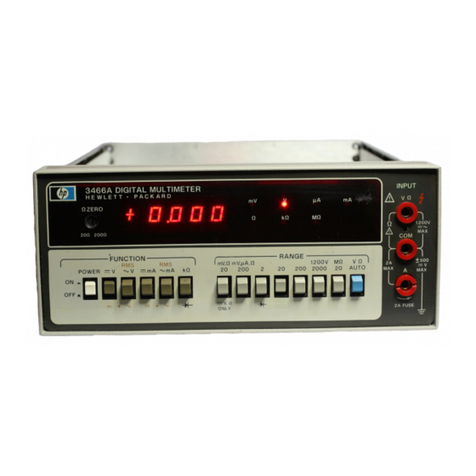
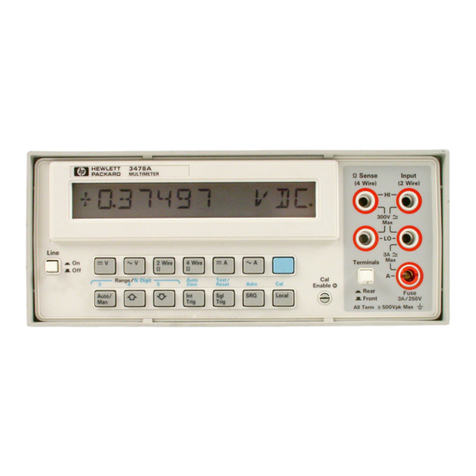
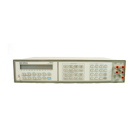
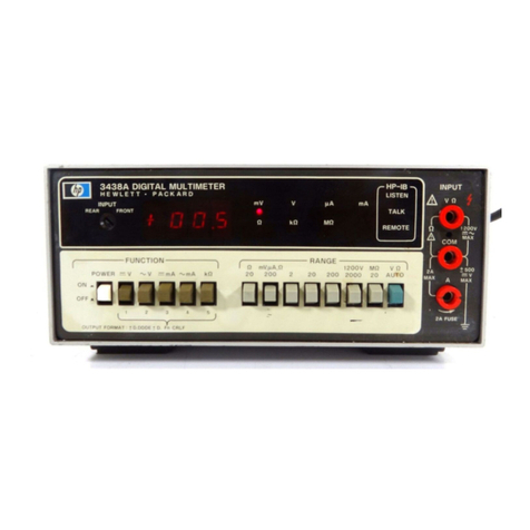
HP 3438A Service manual

OPERATING AND SERVICE MANUAL
MODEL 3438A
DIGITAL MULTIMETER
Serial Numbers
1717A00330
and Greater
IMPORTANT NOTICE
Any changes made in instruments manufactured after
this printing will be found in a "Manual Changes"
supplement, supplied with this manual. Be sure to
examine this supplement, if one exists for this manual,
for any changes which apply to your instrument and
record these changes in the manual.
I
WARNING
)
To
help minimizc. thepossibilitv ofelectrica[fire or
shock
hazards, do not espose this instrument to rain or
excessive moisture.
Manual Part No.
03438-90001
Microfiche Part No.
03438-90051
Printed: February
1978


CERTIFICATIO
N
Hewlett-ljackard Company certifies that this instrzrment met its ~ublished
specifications at the time of shipment from the factory. Hewlett-Packard
Companyfurther certifies that its calibration measurements are traceable to the
United States National Bureau of Standards, to the extent allowed by the
Bureau's calibration facility, and to the calibration facilities of other
International Standards Organization members.
WARRANTY AND ASSISTANCE
This Hewlett-Packard product is warranted against defects in materials and
workmanship for a period of one year from the date of shipment, except that
in the case of certain components, if any, listed in Section I of this operating
manual, the warranty shall be for the specified period. Hewlett-Packard will, at
its option, repair or replace products which prove to be defective during the
warranty period provided they are returned to Hewlett-Packard, and provided
the proper preventive maintenance procedures as listed in this manual are
followed. Repairs necessitated by misuse of the product are not covered by this
warranty. NO OTHER WARRANTIES ARE EXPRESSED OR IMPLIED,
INCLUDING BUT NOT LIMITED TO THE IMPLIED WARRANTIES OF
MERCHANTABILITY AND FITNESS FOR A PARTICULAR PURPOSE.
HEWLETT-PACKARD IS NOT LIABLE FOR CONSEQUENTIAL DAMAGES.
If this product is sold as part of a Hewlett-Packard integrated instrument
system, the above warranty shall not be applicable, and this product shall be
covered only by the system warranty.
Service contracts or customer assistance agreements are available for
Hewlett-Packard products.
For any assistance, contact your nearest Hewlett-Packard Sales and Service
Office. Addresses are provided at the back of this manual.

Model 3438A Table of Contents
TABLE OF CONTENTS
Section
I
.
GENERAL INFORMATION
....
...........
1.1
.
Introduction
1.3
.
Description
...........
..........
.
1.7 Specifications
1.9
.
Instrument and Manual
Identification
........
1-11
.
Options
..............
1
.
14
.
Accessories
...........
1.16
.
Safety Considerations
.....
Page
..........
1-1
..........
1-1
..........
1-1
..........
1-1
Section Page
I1
.
INSTALLATION
.....................
2-1
2.1
.
Introduction
.....................
2-1
2.3
.
Initial Inspection
..................
2-1
2.5
.
Power Requirements
...............
2-1
2.7
.
Environmental Requirements
..........
2-1
2.9
.
Instrument Mounting
...............
2-1
2-11
.
Hewlett-Packard Interface
Bus (HP-IB)
...................
2-1
2-13
.
Interface Cable Length
.............
2-1
2-15
.
Repackaging for Shipment
...........
2-1
2.19
.
Power Cords and Receptacles
..........
2-2
Section Page
111
.
OPERATING INSTRUCTIONS
............
3-1
3.1
.
Introduction
.....................
3-1
3.3
.
AC Operation
....................
3-1
3.5
.
Overload/Overrange/Improper
Function Indication
..............
3-1
Section Page
111
.
OPERATING INSTRUCTIONS
............
3-1
3.1
.
Introduction
.....................
3-1
...................
.
3.3 AC Operation 3-1
3.5
.
Overload/Overrange/Improper
Function Indication
..............
3-1
3.8
.
Auto
........................
3-1
3-11
.
Input Terminals
.................
3-1
3-16
.
DC Voltage Measurements
(Front or Rear Input Terminals)
.....
3-3
3-1
8
.
AC Voltage Measurements
(Front or Rear Input Terminals)
.....
3-3
3.20
.
DC Current Measurements
..........
3-4
3.22
.
AC Current Measurements
..........
3-4
3.24
.
Resistance Measurements
.....
(Front or Rear Input Terminals) 3-5
3.26
.
HP-IB Applications
................
3-5
3.28
.
Data Output Format
..............
3-5
3.32
.
Talk Only Mode
.................
3-5
3.39
.
Addressable to Talk Mode
..........
3-6
3.43
.
-hp-9815A Sa~npleApplication
.......
3-7
3.44
.
-hp-9825 Sample Application
........
3-7
3.45
.
-11p- 9830 Sample Application
........
3-7
3.46
.
Option Decal
...................
3-7
348
.
Amps Input Fuse Replacement
.......
3-7
3.50
.
Multinreter Cleaning
..............
3-7
Section Page
.
................
IV PERFORMANCE TESTS 4-1
.
.....................
4.1 Introduction 4-1
............
4.3 Test Equipment Required 4-1
..................
4.5 Performance Tests 4-1
.
........
4.8 DC Voltmeter Accuracy Test 4-1
.
........
4-1
0
AC Voltmeter Accuracy Test 4-1
.........
.
4-12 DC Ammeter Accuracy Test 4-2
.........
.
4.14 AC Ammeter Accuracy Test 4-3
4-16
.
Ohmmeter Accuracy Test
...........
4-3
4.18
.
AC Normal-Mode Rejection Test
......
4-5
4-21
.
AC Common Mode Rejection
Ratio
.
CMRR
.................
4-5
Section Page
V
.
ADJUSTMENT PROCEDURES
............
5-1
5.1
.
Introduction
.....................
5-1
...............
.
5.3 Equipment Required 5-1
................
.
5.5 Adjustment Interval 5-1
...........
.
5.7 Pre-Adjustment Procedures 5-1
5.9
.
Test Point and
Adjustment Locations
............
5-1
5-1
1
.
Adjustment Procedure
..............
5-1
5.13
.
A +7 V Power Supply
..............
Adjustment (R417) 5-2
5.14
.
BU725 Back Gate
Bias Adjustment (R603)
...........
5-2
5-15
.
Clock Frequency
Adjustment (R9)
................
5-2
5.16
.
AC Zero Adjustment (R203)
....
5-2
5.17
.
20Ohms Zero
Adjustment (R111)
..............
5-2
5.18
.
DC Gain Adjustment (R403)
....
5-2
5.19
.
Ohms Gain Adjustment (R119)
...
5-3
5.20
.
AC Gain Adjustment (R123)
....
5-3
5.21
.
20 V Range, 20 kHz
Adjustment (R102)
..............
5-3
5.22
.
2 V Range, 20 kHz
..............
Adjustment (R110) 5-3
5.23
.
20 V ac Range, 100kHz
Adjustment (C109)
..............
5-3
5.24
.
Power Requirement
Modification Instructions
..........
5-4
Section Page
V1
.
REPLACEABLE PARTS
................
6-1
6.1
.
Introduction
.....................
6-1
...............
.
64 Ordering Information 6-1
..................
.
6.6
Non-Listed Parts 6-1
.
....................
6.8 Parts Changes 6-1
..................
.
6.10 Proprietary Parts 6-1

Table of Contents Model
3438A
TABLE OF CONTENTS (Cont'dl
Section Page
VII
.
MANUAL CHANGES
..................
7-1
7.1
.
Introduction
.....................
7-1
Section Page
VIII
.
SERVICE
..........................
8-1
8-1 Introduction
.....................
8-1
8.4
.
Block Diagram and
Simplified Theory
...............
8-1
8.16
.
Detailed Theory
..................
8-1
Section Page
VIlI
.
SERVICE (Cont'd)
...................
8-1
.
...................
8.17 Powersupply 8-1
.
..................
8.25 Analog Theory 8-2
TROUBLESHOOTING
.........
.
8-51 Preliminary Troubleshooting 8-7
8.56
.
General Troubleshooting
...................
Information 8-8
.........
.
8.61 A1 and A2 Troubleshooting 8-9
.........
.
8.67 HP-IB(A3) Troubleshooting 8-9
LlST OF TABLES
Table Page
1.1
.
Specifications
........................
1-2
1.2
.
General Information
...................
1-4
1.3
.
Options
............................
1-4
14
.
Accessories
..........................
1-4
3.1
.
Improper Switch Combinations
............
3-1
3.2.
.
Output Delays
.......................
3-6
4.1
.
Test Equipment Required
................
4-0
4.2
.
DC Voltmeter Accuracy Test
..............
4-1
4.3
.
AC Voltmeter Accuracy Test
..............
4-2
44
.
DC Ammeter Accuracy
..................
4-3
4.5
.
AC Amnieter Accuracy Test
(200pA Thru 20 mA Ranges)
...........
4-3
4.6
.
AC Ammeter Accuracy Test
(200 mA and 200 11iARanges)
...........
4-4
Table Page
.................
4.7 Ohmmeter Accuracy Test 4-4
................
.
5.1 Test Equipment Required 5-0
.
.............
5.2 Power Supply Voltage Checks 5-2
.
.................
6.1 Standard Abbreviations 6-1
6.2
.
Code List of Manufacturers
...............
6-2
.
.....................
6.3 Replaceable Parts 6-3
.....................
64 Miscellaneous Parts 6.10
8.1
.
Function Code
.......................
8-2
8.2
.
Range Codes
.........................
8-2
.
.........
8.3 General Interface Management Lines 8-7
...........................
.
8.4 AC Gain 8-7
.
...........................
8.5 DC Gain 8-7
.
........................
8.6 Test Jumpers 8-8
8.7
.
Test Pads
...........................
8-9
LlST OF ILLUSTRATIONS
Figure Page Figure Page
2.1
.
Hewlett-Packard Interface 4.6
.
Ohms Accuracy Test
...................
4-5
.
...........
Bus Connector
.....................
2-2 4.7 AC Normal-Mode Rejection Test 4-5
..........
.
2.2
.
Power Receptacles
.....................
2-2 4.8 AC Common-Mode Rejection Test 4-6
...................
.
3.1
.
Overload Indication
....................
3-1 5.1 DC Gain Adjustment 5-2
....................
.................
3.2
.
Multilneter Autoranging 3-1 5.2 AC Gain Adjustment 5-3
..............
.
..........
3.3
.
Front and Rear Panel Descriptions 3-2 5.3 Line Voltage Configurations 54
.................
.
................
3.4
.
DC Voltage Measurements 3-3 5.4 Adjustment Locator .5.5/ 5.6
................
.
................
3.5
.
AC Volta~eMeasurement 3-3 8.1 Simplified Block Diagrarn 8-0
3.6
.
DC Current Measurements
................
3-4 8.2
.
-7 V Regulator
.......................
8-2
3.7
.
AC Current Measurements
................
3-4 8.3
.
Range Code Logic Interface
...............
8-2
3.8
.
Resistance Measurements
................
3-5 8.4
.
DC Gain Coniiguration
..................
8-3
...................
3.9
.
Data Output Format and 8.5 AC Gain Configuration 8-4
Function Codes
....................
3-5 8.6
.
Ohms Block Diagram
...................
8-4
3.10
.
Talk Only Switch Settings
................
3-6 8.7
.
Ohin Gain
..........................
8-5
3-11
.
Talk Only Data Logger
..................
3-6 8.8
.
Integrator Output
.....................
8-6
3-12
.
Address Select Code
....................
3-7 8.9
.
Interface Connections and
3-13
.
9815AIHP-IBApplication
................
3-8 Bus Structure
......................
8-6
3.14
.
9875/HP-IB Application
.................
3.10 8.10
.
Power Supply Jumpers
..................
8-9
3-15
.
9830A/HP-IBApplications
..............
3-1
2
8.1
1
.
HP-IB Troubleshooting Flowchart
.........
.8-11
3.16
.
Option Decal
........................
3-7 8.12
.
Simplified
Analog Schematic
..........
8-1518-I6
4.1
.
DC Voltmeter Accuracy Test
..............
4-2 8.13. 3438A Input Switching, Input Amplifier,
4.2
.
AC Voltage Accuracy Test
...............
4-3 and Ohms Current Source Schematic
.
.
8-17/8-18
4.3
.
DC Ammeter Accuracy Test
..............
4-4 8.14
.
3438A Post Amplifier, AC to DC Converter
.............
4.4
.
AC Ammeter Accuracy Test and Analog to Digital 8-19/8-20
(200pA Thru
20
mA Range)
............
4-4 8.15
.
3438A HP-IB Schematic
.............
8-21/8-22
4.5
.
AC Ammeter Accuracy Test 8.16
.
3438A Display Sche~natic
............
8-2318-24
(200 111A and 2000 mA Ranges)
..........
4-4 8.17
.
Power Supply Schematic
.............
8-2518-26

Model 3438A Section I
SECTION I
GENERAL INFORMATION
1-1. IN'TRODUCTION.
1-2. This section contains general information con-
cerning the -hp- Model 3438A Multimeter. Included is an
instrument description, specifications, information
about instrument and manual identification, option and
accessory information, and safety considerations.
1-3. DESCRIPTION.
1-4. The -hp- Model 3438A is an HP-IB compatible,
3% digit, five function, autoranging multimeter. The
functions are AC and DC Voltage, AC and DC Current
and Ohms. All five functions have manually selectable
ranges. AC and DC Voltage and Ohms functions may
also be automatically ranged by depressing the AUTO
pushbutton.
1-5. The 3438A enablesthe user to set up alowcostdata
gathering system utilizing the HP-IB. Voltage (ac or
dc), Current (ac or dc) and resistance information can be
transferred on the HP-IB to Printers, Calculators,and
Computers for data storage or
hard
cop.^
printouts.
1-6. Throughoutthe remainder of this manual, the-hp-
Model 3438A Multimeter will be referred to as
Multimeter.
1-7. SPECIFICA'I'IONS.
1-8. Specifications for the Multimeter are listed in
Table 1-1. These specifications are the performance
standards or limits towhich the Multimetercan be tested.
Any changes in these specificationsdueto manufacturing
changes, design or traceability tothe National Bureau of
Standards will be covered by an errata or change sheet.
These specifications supersede any prior published
specifications. Supplemental information in Table 1-2 is
provided to describe general operating characteristics.
1-9. INS'TRUMENT AND MANUAL IDENT-
IFICATION.
1-10,
Hewlett-Packard uses a two-section serial
number. The first section (prefix) identifies a series of
instruments. The last section (suffix) identifies a
particular instrument within the series. A letter between
the prefix and the suffix identifies the country in which
the instrument was manufactured. The manual is kept
up-to-date at all times by means of a change sheet which
is supplied with the manual. If the serial number of your
instrument differs from the one on the title page of this
manual, refer to the change sheet supplied with the
manual. All correspondence with Hewlett-Packard
should include the complete serial number.
1-11. OPTIONS.
1-12. Table 1-3 lists the options available for the
Multimeter.
1-13. The option label affixed to the rear of the
Multimeter identifies the line voltage for which the
instrument is wired. This operating voltage can be
changed by followingthe procedure outlined in Section V
(Power Requirement Modification Instructions). If the
line voltage' option is changed, the option labei should
also be corrected to reflect the new configuration.
1-14. ACCESSORIES.
1-15. The accessories available for use with the
Multimeter are listed in Table 1-4.
1-16. SAFETY CONSIDERATIONS.
1-17. This Operating and Service Manual contains
cautions and warnings alerting the user to hazardous
operating and maintenance conditions. Thisinformation
is flagged by a caution or warning heading and/or the
symbol
.
The symbol appears on the
front panel and isaninternational symbolmeaning "refer
tothe Operating and Service Manual". Thissymbolflags
important operating instructions located in Section 111.
To ensure the safety of the operating and maintenance
personnel and retain the operating condition of the
instrument, these instructions must be adhered to.

Section
I
Table
1-1.
Specifications.
Model
3438A
DC
VOLTMETER
Ranges
r
200 mV
f2
v
i
20
v
i
200
v
+
1200
v
Max Display
f
199.9 mV
+
1.999
v
f
19.99 V
+
199.9 V
ill99 V
I
Maximum lnput: 1200 V ldc
+
peak aci
I
Rang~ngAutomatic or manual
I
Sensitivity: 100pV on 200 mVrange.
I
Polar~ty:Automatically sensed and d~splayed
Accuracy: 1Year 15' to 30'~
@
95%RH.
200 rnV
+
(0.1%of reading
+
2 digits)
2Vto
1200V
f
(0.1% of reading
+
1digit)
Temperature Coeflkient: 0'
-
15'~and 30'
-
55'~
i
(018%read~ng
+
0.1 digit) /'C
1
Input Resistance 10rneg
a
f
1%
1
lnput Type: Floating 500 V max COM to ground.
Normal Mode Rejection: 40dB at 50 Hz and 60 Hz
f
.1 Hz.
Effective Common Mode Rejection With 1
ka
unbalance is
>
120 dB at 50160 Hz
t
0.1
%
Response T~me:
<
0.7 seconds to within 1 digit of final
value on any range. Add 1second for each range
change.
AC Converter: Avg. Respond~ngrms calibrated
Ranges Max Display
200 rnV 199.9 mV
1.999
v
19.99 V
200 V 199.9 V
1200 V 1199
Maximum Input: 1700V (dc
+
peak ac),
lo7
volt
Hz max.
Ranging. Automatic or manual
Sensit~vity:100 pV on 200 mV range
Accuracy 1
year, 15' to30'~
@
95% R
H
Temperature Coefficient: 0'
-
15'~and 30'
-
55'~
f
(0.04% of read~ng
+
0.2 digits) lac.
Minimum Reading: 20 d~gits.
lnput Impedance. Resistance: 5 rneg
a.
Shunt Capacitance:
<
50 pF
30.H~
-
50 Hz
50 Hz
-
20 kHz
20 kH7
-
100 kHz
lnput Type: Floating 500 V max COM to ground.
i
(1
.5%
of reading
f
3digits)
i
(0.3%of readlng
t
3 digits)
i
(1.5%of reading
?
10digits)
Response Time: 1.6seconds to within
3
digits of final
value on any range. Add 1.2 seconds for each
range change.
1
DC
AMMETER
Maximum Input: 2A from
<
250 V source.
Protection: 2A1250 V fuse (normal blow)
Ranging: Manual only.
Sens~tiv~ty:100 nA on 200 PA range.
Polarity: Automatically sensed and displayed.
Accuracy: 1year, 15 to 30°C
@
95% RH.
2000 mA
+
(0.616 of reading
+
2 digits)
Temperature Coefficient: 0
-
15OC and 30
-
55OC
f
(.028%of reading
+
0.1 digits)l0C.
Voltage Burden:
Max Burden
at FullScale
200 mA
<
240 mV
2000 mA
<
400 mV
lnput Type: Floating 500
V
max COM to ground.
Response Time: 0.7 seconds on any range to within
1d~g~tof final value.
AC AMMETER
Ranges Max Display
200 PA 199.9PA
1.999 mA
20 mA 19.99 mA
200 mA 199.9 mA
2000 mA 1999 mA
Maximum Input: 2A from
<
250 V source.
Protection: 2A1250 V fuse (normalblow).
Ranging: Manual only
Sensitivity: 100 nA on 200 PA range.
Accuracy: With display of
2
20 digits.
1year 15to 30'~95% RH

Model
3438A
Section
I
Table
1-1.
Specifications (Cont'd).
OHMMETER
Specifications
*
(2%of
*
11.2%of reading
reading
t
4 digits)
*
4 digits)
t
I1.7% of
reading
k
4 digits)
?
(0.9%of reading
t
4 digits)
30Hz 50 Hz 10kHz
Frequency of lnput Slgnal
Temperature Coefficient. 0
-
15'~and 30
-
55'~
?
10.05% of reading
+
0.2 digits) l0C.
Voltage Burden:
lnput Type: Floating 500 V max COM to ground.
Response Time: 1.6 seconds on any range towithin
3 digits of final value.
lnput Protection: 250 V rms
Ranging: Automatic, or manual
Sensitivity:
10milliohm on 20
C2
range.
Accuracy: 1 year 15to 30'~at 95%
Rk:
Range
20
n
--
Specification
2
(0.5%of reading
+
10
digits)
200
C2
to
2
Ma
20 M57
20 Ma
(
?
(.18%of reading
+
0.2 digits)
/OC
t
(0.2% of reading
+
2 digits)
2
(0.8%of reading
+
2 digits)
Temperature Coefficient: 0
-
15'~and 30
-
55OC.
Configuration: 2 wlre.
Range
Open Circuit Voltage:
<
5 V max
Specifications
20
C2
to2Mn
(
2
(0.04%of reading
+
0.2 digits) 1°C
Current through unknown:
In accordance w~thIEEE-488-1975, the 3438A Multin~etel
meets the following Interface Function Specifications.
I
Interface
Function
DT
1
RL2
LLO
SRQ
PPO
DCO
Response Time: 0.8 seconds to within 1digit of final
value. Add0.8 seconds for each range change.
Description
Source handshake
Acceptor handshake
Talker (basic talker, talk only mode
unaddress-to-talk ifaddressed-to-
listen
Listener (basic listener, unaddress-
to-listen ~faddressed-to-talk)
Open collector Bus driver
Devicetrigger
Remote!Local
Local lockaut
Servlce Request
Parallel poll
Device clear
Controller
2Mn
500nA
Range
Current
3438ACapability
20Mn
50nA
2052
5mA
200R
5rnA
20kR
50pA
2kn
500pA
200kn
5pA

Section
I
Table
1-2.
General Information.
Model
3438A
GENERAL:
Display: 7 segment RED 0.3 inch high LED'S.
Functionand range annunciation.
Read~ngrate: 2.4
-
4.71sec. depending on Input level
A-DConversion. Dual slope.
lntegration time: 100msec.
Ranging: Automatic or manual inac V, dc V and ohms.
Manual onlv inac and dccurrent.
Storage Temperature: (40to +75j0c;
Humidity. 0
-
95% RH at 40'~
Power. AC line; 48
-
440 Hz 86-106 V Opt. 100
104-127V Opt. 115
190~233V Opt. 210
208-250
\I
Opt. 230
Total Instrument Power Dissipated: 12 watts
Configuration: 3438A Std, Rack and Stack case, ac
line power only. Rack mount kitnot included.
Dimensions: 20.96 cm (8114") w~de
x
8.57 cm
(3318") high
x
31.12 cm (12 114 in.)
Operating Temperature. (0to 55)'~. Weight: 2.87 kg (6Ibs. 5 02.)
Table
1-3.
Options.
Standard Rack mount case. AC line operation only.
Option 100 86
-
106 Vac 48
-
440 Hz 12Watts
Option 115 104
-
127Vac 48
-
440 Hz 12Watts
Option 210 190
-
233 Vac 48
-
440 Hz 12 Watts
Option 230 208
-
250 Vac 48
-
440 Hz 12 Watts
Option 908 Rack Mount Kit
.
hp-Part Number 5061-0054.
Option 910 An add~tionalOperat~ngand Serv~ceManual.
Table
1-4.
Accessories.
Test leads (dual banana to dual alligator).
Test leads dual banana to probe and alligator.
RF Probe 10 kHz to 700 MHz, use only 10V and
100V dc ranges.
Rack adapter kit iqcluding
%
module filler panel.
Soft vinyl carryingloperating case.
tllgh voltage probe, 40 kVdc
Touch
-
Hold, Input probe.
Test lead klt.
Test leads, dual banana onbothends
1
M (39.37") HP-I B Cables
2M (78.74") HP-IB Cables
4M (157.48") HP-I B Cables

Model 3438A
SECTION
II
INSTALLATION
Section 11
2-1. INTRODUCTION.
2-2. This section.containsinformation and instructions
for the installation and shipping of the Multimeter.
Included are initial inspection procedures, power and
grounding requirements, environmental information,
and instructions for repackaging the instrument for
shipment.
2-3. INITIAL INSPEC'I'ION.
2-4. This instrument was carefully inspected both
mechanically and electrically before shipment. It should
be free of mars orscratchesand in perfect electricalorder
upon receipt. To confirm this. the instrument should be
inspected for physical damage in transit. Electrical
performance should be tested using the performance test
outlined in Section
V.
If there is damageor deficiency, see
the warranty insde the front of this manual.
2-5. POWER REQUIREMENTS.
2-6. The Multimeter can be operated from any one of
the ac power sources listed in Table 1-2. Before
connecting the instrument to ac power, verify that the ac
power source matches the power requirement of the
instrument as marked on the option label affixed to the
rear of the instrumept. If the instrument is incompatible
with the available power source, refer to Section
V
for
Power Requirement Modification instructions.
2-7. ENVIRONMENTAL REQUIREMENTS.
2-8. The lblultimeter will meet the s~ecificationslisted
in Table 1-1 when the operatingtemperature is within the
range of
+
15°C to
+
30°C. The instrument can be
operated where the ambient temperature is within the
range of 0°C to
+
40°C and the relative humidity is less
than 95%.
pii-1
Toprevenf potential electrical or,firehazard,
donor expose equipment to rain or moislure.
2-11. HEWLETT-PACKARD INTERFACE
BUS (HP-IB).
2-12. Figure 2-1 illustrates the rear panel HP-IB
connector, along with a brief description of each signal
line.
2-13. Interface Cable Length.
2-14. The maximumaccumulativelength of an HP-IB
cable in any system must not exceed more than 2 meters
of cable per device (up to 15 devices) or 20 meters,
whichever is less.
2-15. REPACKAGING FOR SHIPMENT.
2-16. The following paragraphs contain a general guide
for repackaging the instrument for shipment. Refer to
Paragraph 2-17 if the originalcontainer is tobe used, 2-18
if it is not. If you haveany questions, contact your nearest
-hp- Sales and Service Office. (See Appendix Aforoffice
locations.)
NOTE
If fheinsfrument is to beshipped to Hewleff-
Packard,forservice or repair, attach a tag to
[he insfrument ident~fyingthe owner and
indicafing the service or repair to be
accomplished. Include themodel number and
,fullserial number of the instrument. In any
correspondence, identify the instrumen1 by
model number and,fullserial number.
2-17. Place instrument in original container with
appropriate packing material and seal well with strong
tape or metal bands. If original containeris notavailable,
one can be purchased from your nearest -hp- Sales and
Service Office.
2-18. If original container is not to be used, proceed as
follows:
2-9. INSTRUMENT MOUNTING.
a. Wrap instrument in heavy paper or plastic
before placing in an inner container.
2-10. The Multimeter is shipped with plastic feet and
tilt stand in place, ready for use as a bench instrument. b. Place packing material around all sides of
The front of the instrument may be elevated for instrument and protect front panel with cardboard strips.
convenience of operating and viewing by extending the
tilt stand.The plastic feet areshaped topermit placing the c. Place instrument and inner container in a heavy
instrument on top of other System I1half or full module carton or wooden box and seal well with strong tape or
Hewlett-Packard instruments. metal bands.

Section
I1
Model
3438A
HP-IB
CONNECTOR
5701
CHASSIS/OUTGUARD
GROUND
0
0
0 0
a
r
,
Dl0
1-8
(Data Input/Outputl
Mnemonic referring to the eight "Data Input/Output"
lines. The Dl0 lines transfer messages in a byte-serial.
bit parallel manner.
€01 (Endor Identify)
Mnemonic referring to the "End or Identify" control
line. €01 is used by a device to indicate the end of a
multiple-byte transfer.
DAV (DataValidl
Mnemonic referring to the "Data Valid" control line.
DAV is used to coordinate the "handshake" sequence.
T'ie DAV line is controlled by the source (talker). When
DAV is true, data on the Dl0 lines is considered valid.
NRFD (Not Ready For Datal
Mnemonic referring to the "Ready For Data" control
line. NRFD is used to coordinate the "handshake"
sequence. The NRFD line is controlled by the acceptor
(Ilstener). When NRFD is true, the acceptor indicates to
the source that he is ready to accept data.
NDAC (Data Not Accepted)
Mnem~nicreferring to the "Data Accepted" control line.
NDAC is used to coordinate the "handshake" sequence.
The NDAC line is controlled by the acceptor (listener).
When NDAC
is
true, the acceptor indicates to the source
that the data on the Dl0lines has been accepted.
Mating Connector:
-np- Part No. 1251-0293
AmDnenol No. 57-30240
Mating Cables:
10631A 3 ft.
106318 6 ft.
10631C 12 ft.
the source that the data on the Dl0 lines has been
accepted.
IFC (Interface Clear)
Mnemonic referring to the "Interface Clear" control line.
IFC is used to place the HP-IB system ina known quies-
cent state. The IFC line is controlled by the system
controller.
SRQ (Service Request)
Not
Availablr
in
3438A
Mnemonic referring to the "Service Request" control
line. SRQ is used (by any device having service request
capability) to indicate to the system controller that the
device requires service. The controller responds by polling
the devices to determine which device requested service.
ATN (Attention)
Mnemonic referring to the "Attention" control line. The
state of the ATN line determines whether the HP-IB is in
the "Command mode" (ATN true) or the "Data mode"
(ATN false). When ATN is true, all devices must listen to
the data lines. and when ATN is false, only devices that
have been addressed will actively transfer data.
REN (RemoteEnable)
Mnemonic referring to the "Remote Enable" control
line. REN is used in conjunction with listen addresses
(Dl0
1-8)
to select either local or remote control of each
device.
For further information concerning the HP-IB, refer to
"Hewlett-Packard Interface, A Compendium of Technical
Articles" -hp- publications No.
5952-2472.
Figure
2-1.
Hewlett-Packard Interface Bus Connector.
2-19.
POWER CORDS AND RECEPTACLES.
2-20.
Figure
2-2
illustrates the plug cap configurations
that areavailable to provide ac power to the Multimeter.
The-hp- part number showndirectly below each plug cap
drawing is the part number for the power cord set
equipped with the appropriate mating plug for that
receptacle. The appropriate power cord should be
provided with each instrument. However, if a different
power cord set is required, notify the nearest -hp- Sales
and Service Office and a replacement cord will be
provided. The instrument ac power input receptacle and
cord set appliance coupler meet the safety specifications
set by the International Commission on Rules for the
Approval of Electrical Equipment (CEE
22).
8120-1351 812k1369 8120-1689
elm-1348
,TO
n-4m
.UL
LISTED
FOR
USE
IN
THE
UNITED
STATESOF
AMERICA
Figure
2-2.
Power Receptacles.

Model 3438A
SECTION
Ill
OPERATING
INSTRUCTIONS
Section
111
3-1. INTRODUCTION. 3-8. Auto.
3-2.
1
his section contains instructions for operating the
Multi~neter.Mcaburements of ac and dc voltage, ac and
dc currcnt. and ohmsare discussed. Sampleapplications
will be given in thih xction to demonstrate the use of the
Ill'-ltl. A description of the controls and connectors is
givcn in Figure
3-3.
I
WARNING
,
)
Toprevent potential electrical orfire hazard,
do not e-rpose the Multimeter or its
accessories to rain or moisture.
3-3. AC Operation.
3-4. Before connecting the Multimeter to ac power,
verify that the ac power source matches the power
requirements the Multimeter as marked on the option
label affixed to the rear of the instrument. If the
instrument is incompatible with the available power
source, refer to Section V of this manual for power
requirement modification instructions. After this
verification, connect the proper ac power to the
instrument and press the ON button. The instrument is
ready for use.
3-5. Overloadloverrange/Improper Function
Indication.
3-6.
tigure 3-1 shows the display indication during
overload, overrange, or an improper switch setting.
Figure 3-1. Overload Indication.
3-7. Table 3-1 lists improper switch combinations.
Table 3-1. Improper Switch Combinations.
3-9. Depressing the AUTOswitch with acV, dcV or k R
function selected sets the Multimeter in an automatic
ranging mode. In this mode the Multimeter will
uprange
if the display increases above
(+)
or
(-)
and
downrange
if the display decreases below
(+)
or
(-)
.
These numerical autoranging points are
irrespective of decimal placement. The difference
between the two autoranging points is called
autoranging
Il~~.s/r~r.r~.vis.
Figure 3-2 shows the autoranging points for
dc voltage measurements from 0 to 1200
V
dc.
Autoranging in other Multimeter functions is similar.
Function
v
-v
mA
-mA
> >
a
P
>
'D
I
1.
C
I
I
.
C
E
>
> > > >
-
m
0
?
m
0:
i
8::
X
p
E' E'
2
z
e
4
INPUT LEVEL (Vdc)P
f
=DOWNRANGE POINT
*=
UPRANGE POINT
Figure
3-2.
Multimeter Autoranging.
Range
3-10, To release the AUTO switch depress one of the
MANUAL RANGE switches.
mv.a
20
mV,a
20
mv,
a
20
3-11. lnput Terminals.
3-12. lnput Selector Switch.
The Input Selector
Ma
20
Mn
20
Ma
20
Ma
20
Switch (front panel) is used to select front or rear input
terminals. Inthe FRONTposition, the VR,COM,and A
input terminals are internally connected to enable the
user to make voltage, current, and resistance
measurements from the front panel. With the Input
Selector switch set to REAR, the V R and COM input
terminals on the rear panel are connected to allow the
user to make voltage and resistance measurements.
Auto
Auto
NOTE
Thereis no current measuring capabilityfrom
the rear input terminals.

Sezt~ori
Ill
Model
3438A
I
DESCRIPTION
POWER OK:OFF SWITCH. SWlrCHES MlJLTlMETER
POWER ON OR OFF
I
FUNCTION SWITCHES: I;SED TO SELECT THE
FIVE
I
ClUI.TICIETER FI'NCTIONS.
I
@
I)( YO1 1(;F
I
IVCI(OUSWIICH
.2( LOl.IACII tliU('IIO\ SWI I( H
L)C 4411 I IAMI'I RtS
I
I
\CIIU\ SWIICH
@
.\C V11
1
IZMI't Kt:>
tI
\(.llON SMIICH
@
KI10tiMS tIIUC 110\ 5WIIC.H
@
2
YOLI, hlll
l
Iihfl'
\\I)
KIIOtrM Kt\U(it SMIICH
LO
\OL.I.
\ill
I
IAMI'
,\\I)
hILOIIL1 KAU(iF SMIrC.11
All10 R,\U(;L SMIICH \IITOLi,4IICAL.L.Y StlCCIS
K4\GL I-OR 131-Sl Kt\OI
I1
110\
WHI-N
R('
LO1 IS.
I)('
VOLIS.
OK
OHMS
F
I
\CIIOYS
AKF
SEI.FCIFI)
15
2\11'S
111'1
1 ItKMI\1I. LISFI) IUCOUJI
\('IIC)\
WIIH
*
IHECO21 ICKMl\hl ).OK \liASI~Kllli;
hC
\VI)
I)(.
C1:RKLN
I
AI 501151
1)
kOK
KIAI)I\(; llOL
1)
1\1'I
1
@)
COLI I\PLI I IIKMI\AI COMMO\ UFKMINAL I-OK
C
I I
I.
C I)C A\il'S 4\1) OHMS Mt,hSLKt:-
MEXIS
I7 LO1 15 OHMS 1\P181ILK\II\AI IlSf l)I\CO\.IIINCII(.)U
*
MIH ,HE COM 1LRMIV.l l,OK kll~,\SIKlVCi ,\C l)C
LO1 14CiL 2UI) OH\?';
20
I>ISPIhY 1.01 K SLC
I10\
1.t1)
I<FhI~OII
I
I
tt
1
St<
1
IOW
O
1)ISI'I
.\YS+
I KI(,II I IHIIFFSEC IIONSA1<F7Sb.(iMl UI
21
l\PIII SELECIOK SWIIC H IN IHt
REAR
POSIIION. IHI~
!!i~
AVI) COh4 I\PL IS A.KE SWI ICHkI)
I0
IHI. RFAK
I'\UtL 211)
I
ILL tKC)\
I
1'-\YE.[ IVPC
1-
I-EKMlNA1.S AIIF
01'1.Y. lU r11t
FRO1T
POSI
110\.
IHLREAR PAVE1 INI'I.
I
@)
AC.
l'O\bl:K KECtl'l
hC.1
L
@
111,
In
(,OY\l-C
Ion
@
,\C
I,O\VFlI l\t'1,
I
t
LSk
@
COW
l\l>ll
I I
tl<\4lUAl S,hMt ,AS
@)
EXCE:I>l
\O
(
IIKRt\
I
UtASIIl<t-Mt\IS
WHEl
IlSI\(; KCAK ItKMI-
\.\I
S
@
b
11
[\PI
I
11 K\iI\,\l \Abll- AS
@
WHI V lI\lU(.i KtAK
IFKMI\AIS
@)
I'OWbK
I
IUI CrKOL'\I) I1KMILAI
@)
SI.KIhI UIIMHLK.
I
IYC \'OI IAGC
I
AHtl
Figure
3-3.
Front and Rear Panel Descriptions.
3-2

Model
3438A
Section
111
Toavoid possible damage to the Multimeter,
do not change the position of the Input
Selector switch while voltage is connected to
thefront or rear input terminals.
3-13.
VR
(Volts/Ohms).
The VR terminal (front or
rear panel) is the
high
terminal for ac and dc voltage
measurements. For ohms measurements, it is the positive
(+)
terminal.
3-14. COM (Common).
The COM terminal is used for
all five Multimeter functions. It is the negative
(-)
terminal for ohms measurements and it is the
low
terminal foracand dcvoltage and current measurements.
The rear panel COMterminal is onlyused for voltageand
resistance measurements.
To avoid possible damage to the Multimeter
circuitry, the voltage between COM and
(earthground)must not exceedplusor minus
500
V
dc.
3-15. A (Amps).
TheA terminal is the
high
terminalfor
ac and dc amps measurements. There is a 2 amp input
protection fuse in series with this terminal.
The current function isprotected by afuse of
250
V
rating. To avoid damage to the
Multimeter, current sources having open
circuit voltages greater than 250
V
(dc +peak
ac) must not be connected to the
A
(aqps)
input terminal.
3-16. DC Voltage Measurements (Front or Rear
lnput Terminals).
To avoid possible damage to the Multimeter
circuitry, thedc input voltage must not exceed
I200
V
(dc
+
peak ac).
3-1
7.
Procedure.
a. Depress
-7-
V (dc volts).
b.
Depress proper manual range (200 mV to 1200 V)
or depress AUTO for automatic range selection.
c. Connect test leads fromthe Multimeter VR (high)
and COM (low) terminals to the voltage under test as
shown in Figure 3-4.
Figure 3-4.
DC
Voltage Measurements.
3-18.
AC
Voltage Measurements (Front or
Rear lnput Terminals).
To avoidpossible damage to the Multimeter
circuitry, theac input voltage must not exceed
1700
V
(dc
+
peak ac).
3-19. Procedure.
a. Depress V (ac volts).
b.
Depress proper manual range (200 mV to 1200 V)
or depress AUTO for automatic range selection.
c. Connect test leads from the Multimeter VR (high)
and COM (low) terminals to the voltage under test as
shown in Figure
3-5.
INPUT
v-n
n
N
COM
AC
VOLTAGE
SOURCE
2A
FUSE
1
I
I
Figure 3-5. AC Voltage Measurement.

Section I11 Model
3438A
3-20.
DC Current Measurements.
3-22.
AC Current Measurements.
The currentfunction isprotected byafuse of
250
V
rating. To avoid damage to the
Multimeter, current sources having open
circuit voltages greater than 250
V
(dc +peak
ac) must not be connected to the
A
(amps)
input terminal.
The currentfunction isprotected byafuse of
250
V
rating. To avoid damage to the
Multimeter, current sources having open
circuit voltages greater than 250
V
(dc +peak
ac) must not be connected to the
A
(amps)
inpur rerminal.
3-21. Procedure: 3-23. Procedure:
a. Depress
---
mA (dc milliamperes). a. Depress
-
mA (ac milliamperes).
b.
Depress proper manual range (200pAto 2000mA).
b.
Depress proper manual range (200p to 2000 mA).
c. Connect test leads from the Multimeter A and c. Connect test leads from the Multimeter A and
COM terminals in series with the current under test as COM terminals in series with the current under test as
shown in Figure
3-6.
shown in Figure
3-7.
\
\
AC
34661
-
8
-
10
CURRENT
SOlRCE
Figure 3-7. AC Current Measurements.
34

Model 3438A Section I11
3-24. Resistance Measurements(Front or Rear
lnput Terminals).
3-25.
Procedure:
a. Depress kn(kilohms).
b. Depress proper manuaI range or Auto for
automatic range selection (20 to 20 Mn).
c. Connect test leads fromthe Multimeter V ni(=)and
COM
(-)
terminals to the resistance under test as shown
in Figure 3-8.
NOTE
Whenmaking resistance measurementsusing
the lower ohms ranges, consideration should
begiven tothe resistance of the test leads. This
potential measurement error can be elimi-
nated by measuring the lead resistance and
subtracting it from the combined resistance
value of the test leadsand the resistanceunder
test.
\
INPUT
A
ZA
FUSE
1
Figure
3-8.
Resistance Measurement.
3-26. HP-16 APPLICATIONS.
3-27. Examples of typical HP-IB System operations
using the 3438A Multimeter are given to aid the user in
setting up his own system. There are two usable HP-IB
modes of operation:
a. Talk Only.
b. Addressed To Talk.
Both modes will be discussed in the following
paragraphs.
3-28. Data Output Format.
3-29. The Data Output Format and Function Codes are
shown in Figure 3-9.
-
-
+DDDD EI-D
1
F
C
R
LF
-N-
-7
-
-
-
-
D~splay Exponent Del~rn~ter Funct~on Carnage L~ne
-2
Code Return Feed
lnput
Value
ACI
OHMS
Figure
3-9.
Data Output Format and Function
Codes.
3-30. The Data Output Format is a fixed length of 13
characters. The Display and Exponent portion combine
to relate the actual input value.
Example:
If the Multimeter display reading was
+
17.90
V
in the
dcV function, the output format would be:
+
1.790
E
+
I,
I
\Function Code
Input Value
NOTE
There is no leading zero suppression.
3-31.
Overload Indication.
The output format for an
Overload Indication is:
I.DDD E
+
9,
F,
CR, LF.
\Ek/
Overload Indication
The leading 1and the
+
9exponent signifies an overload
indication.
3-32. Talk Only Mode.
3-33. The Talk Only Mode is used in an HP-IB system
without a controller. The Address Switches AS6 and
AS7, which are located on the A3 Logic board (remove
top cover), must be set as shown in Figure 3-10 for this
mode. AS1 through AS5 may be set in any position.

Model
3438A
ADDRESS
SWITCHES
ADDRESSABLE TALK ONLY AS7
OPERATE TEST AS6
0
AS5
0
AS4
0
0
AS2
0
'7
SWITCHES
MAY
BE
SET
IN
ANY
POSITION
FRONT ~~~EA-B-s
Figure 3-10. Talk Only Switch Settings.
3-34. In the Talk Only mode with no other devices
connected to the Multimeter, the Multimeter inputs are
sampled continuously at a rate of 2.4-4.7/sec
determined by the exact input level. Data is output atthe
HP-IB terminal
asjasr
as it is obtained. Refer to Table
3-2.
Table 3-2. Output Delays.
"After
100
rns
Auto Zero
Bus Commands
GroupExecute Trlgger (GET1
Dual Slope Convers~on
Multlmeter Output Avallablllty
GET
thru Output
Availability'
T~rne
toOutput Data tothe HP-IB
Tlme to Accept Data from the HP-lB
3-35. With otherdevices connected tothe Multimeter via
the HP-IB. the output data rate is determined by the
slowest Listener. The following application shows a
simple data logging system using the -hp- Model 3438A
Multimeter and the -hp- Model 5150A Thermal Printer.
Tlme Requlred
<
1 msec
<
300 msec
<
9
msec
<
310
rns
<
900ps
+
Llstener delay
310psicharacter,
100psicharacter typlcal
3-36. Procedure:
a. With both instruments OFF, connect the HP-IB
cable between them.
b. Set Printer to LISTENING (back panel).
c. Set Printer PRINT COMMANDswitchtoLF(1ine
feed).
d. Set the Printer front panel to the desired Print
Interval.
NOTE
If'
the selected print interval is less than the
Mulritneter output rate, the actual print
interval
will be equal to the Multimeter
sample period.
e. Set the PRINTTIME switch to Sep Line (separate
line).
f. Set the Multimeter Address Switch to Talk
Only/Operate as shown in Figure 3-10.
g. Select the desired Multimeter Function and Range
and connect the Multimeter to the unknown voltage,
current, or resistance.
h. Switch both instruments ON and set the printer
clock time (front panel). The Multimeter TALK
annunciator light should be ON.
3-37. This system will print the Multimeter dataand the
Printer clock time. Any HP-IB compatibleLISTENER
can be used in place of the -hp- Model 5150A Printer for
this system.
3-38. If Option 003 is installed in the 5150A Printer, as
many as thirteen 3438A Multimeters can be scanned on
one HP-IB data logger system.
3-39. Addressable to Talk Mode.
3-40. The Addressable to Talk Mode is used in a system
with a controller such as a calculator or computer.
Figure 3-11. Talk Only Data Logger.
3-6
THERMAL PRlNTER MULTIMETER
hp
5150A
hp
3438A
=
0
0
000
0
0
Lu
B
P
34381-8-
1
CABLE
w
C
0<
OPTION
001
8
004
INSTALLED
oooonn
00000000
0

Model 3438A Section 111
3-41. The Talk Address is user selectable by the
internal Address switches As1 through AS5. The
Multimeteris shipped with address select code 23as
shown in Figure 3-12. This switch is binary coded,
i.e., AS5 has weighting of 25
=
16, AS4 has
weighting of 2
=
8, etc.
ADDRESSABLE
OPERATE
0
0
0
0
0
ADDRESS
SWITCHES
FRONT
101111
=2310
TALK ONLY AS7
TEST AS6
1
(16) AS5 (MSD)
AS4
I (2) AS2
I (I) AS1 (LSD)
Figure
3-12.
Address Select Code.
3-42. Sample Applications using three different -hp-
calculators (9815A, 9825A, and 9830A) will be shown in
the following examples. In each of these examples, the
Multimeter is set to the Addressable to Talk Mode.
3-43. -hp- 9815A Sample Appllcatlon.
(See Flgure 3-1
3.
9815AlHPIB
Appllcatlon.)
3-44. -hp- 9825 Sample Application.
(See Figure 3-14. 9825lHP-IB
Application.)
3-45. -hp- 9830 Sample Application.
(See Figure 3-15. 9830AlHP-IB
Application.)
3-46. Option Decal.
3-47. the option decal is affixed to the rear of the
Multimeter. An example is shown in Figure 3-16.
186-106-Vl 1104 127-V
MADE
IN
U
S
A
11
90 233-vl 1208 250-V
HP
3438A
MULTIMETE
I
1
Figure
3-16.
Option Decal.
3-48. Amps Input Fuse Replacement.
3-49. The amps input is protected by a 2A 250
V
normal
blow fuse, -hp- Part Number 2110-0002. This fuse is
easily replaced using the following procedure:
a. Insert a coin or wide bladed screwdriver into the
slots of the A input terminal.
b. Press the color ring in and rotate it counterclock-
wise 1/3turn.
c. Remove and replace the blown fuse.
3-50. Multimeter Cleaning.
Do no1 allorij cleaning solven~s.~/luxremover,
or alcohol lo come in conlac1 wilh /he
Multimeter.
3-51. The Multimeter case and front panel should only
be cleaned with a mild solution of soap and water and a
soft cloth.

Section
I11
Model
3438A
CALCULATOR 10631A/B/C
l
NTERFACE
hp
98135A
MULTIMETER
hp
3438A
HP-IB CABLE
Figure 3-13. 9815AlHP-IB Application.
9815A PROGRAM
#1
I
9815A PROGRAM #I PRIN'TOUT
ENTER
O
lj
r
i
;?
3438A ADDRESS
&,j
*;i
1:
:,;
1.;
'[
,:;
;,
?
GO
r0
REMOTE
(REN)
u
p
.::
;;,
i
,
;;
,
0
ij
i
.i
PAUSE
9
0
1,
4
;:-
,.;
f,.
ri
,
::;
:-
-.
~
,
t!l.(.,r:.
3438A
ADDRESS
3438A (GET)
0
<?
4.
ti
I!
,:;
ci
ii
.>
5
.j
-
.
-
.-
..
8
6
'-'
;
::I
..
-,
-
OOZ;?
F'EHIl'.'
5
0
>
,q
'..:
+
'
.'
-_
.
I
0
u
'::
Ei
::;
i:
1
INPUI AND
11
0
:::
2
F'
F:
I
1.4
T
PRINT 3438A
~1
~1
7
':#
>.:;
+
'(
_ _
_I
-8
DATA
00:34
FI:..:
0
0
0
13
6
F'
F:
I
1.i
T
it
3
7
::;
F'
A
1;.
-
-
-
E
[i
ij
2:
E;
i;
CI
T
[I
8
9
1
7
r:104<i
EIID
......
EXPI.ANAl'ION
2.430 01 REPRESENT 2.43~10~
=
24.3 V
dc
I
=
FUNCTION
I
(dc
V)
,
--
1
[i
,
+:
:
I
.:
i
!
....
!
I
,.
.
.+'
-:
.
..
...
,
--
.i
:.,i
1
.....
..
.:,
:
.
k:i
t'
1
,
.
!,
!
i.7
,
I
,
;
,)
11,
'
1
........
-
,
,I;
L:!
:.;
.4
L.?
1
-t.,.l3ij
;j0
1
:
,
1
I
3
1
i.ii30
EIO
1
i?
.
ij
0
3
r:i
Q
1

Model
3438A
Section
111
9815A
PROGRAM #2
9815
PROGRAM #2
PRlN
1-OUT
Other manuals for 3438A
1
Table of contents
Other HP Multimeter manuals