HP E1326B User manual

-~
ARTISAN
®
~I
TECHNOLOGY
GROUP
Your definitive source
for
quality
pre-owned
equipment.
Artisan Technology
Group
Full-service,
independent
repair
center
with
experienced
engineers
and
technicians
on staff.
We
buy
your
excess,
underutilized,
and
idle
equipment
along
with
credit
for
buybacks
and
trade-ins
.
Custom
engineering
so
your
equipment
works
exactly as
you
specify.
•
Critical
and
expedited
services
•
Leasing
/
Rentals/
Demos
• In
stock/
Ready-to-ship
•
!TAR-certified
secure
asset
solutions
Expert
team
ITrust
guarantee
I
100%
satisfaction
All
tr
ademarks,
br
a
nd
names, a
nd
br
a
nd
s a
pp
earing here
in
are
th
e property of
th
e
ir
r
es
pecti
ve
ow
ner
s.
Find the Keysight / Agilent E1411B at our website: Click HERE

Contents
HP E1326B/E1411B 5 1/2 Digit Multimeter User’s Manual
Edition 4
Warranty . . . . . . . . . . . . . . . . . . . . . . . . . . . . . . . . . . . . . . . . . . 7
WARNINGS . . . . . . . . . . . . . . . . . . . . . . . . . . . . . . . . . . . . . . . . 8
Safety Symbols . . . . . . . . . . . . . . . . . . . . . . . . . . . . . . . . . . . . . . 8
Declaration of Conformity . . . . . . . . . . . . . . . . . . . . . . . . . . . . . . . . . 9
Declaration of Conformity . . . . . . . . . . . . . . . . . . . . . . . . . . . . . . . . . 10
Reader Comment Sheet . . . . . . . . . . . . . . . . . . . . . . . . . . . . . . . . . . 11
Chapter 1. Getting Started with the HP E1326B/E1411B Multimeter . . . . . . . . . . . 13
About This Chapter . . . . . . . . . . . . . . . . . . . . . . . . . . . . . . . . . . . . 13
Multimeter Overview . . . . . . . . . . . . . . . . . . . . . . . . . . . . . . . . . . . 13
Functional Description . . . . . . . . . . . . . . . . . . . . . . . . . . . . . . . . 14
Electrical Description . . . . . . . . . . . . . . . . . . . . . . . . . . . . . . . . . 14
Physical Description . . . . . . . . . . . . . . . . . . . . . . . . . . . . . . . . . 15
Introduction to Operation . . . . . . . . . . . . . . . . . . . . . . . . . . . . . . . . . 16
Multimeter Self-Test . . . . . . . . . . . . . . . . . . . . . . . . . . . . . . . . . 16
Resetting the Multimeter . . . . . . . . . . . . . . . . . . . . . . . . . . . . . . . 17
Making a Measurement . . . . . . . . . . . . . . . . . . . . . . . . . . . . . . . . 20
Chapter 2. Configuring the HP E1326B/E1411B Multimeter . . . . . . . . . . . . . . . . 21
About This Chapter . . . . . . . . . . . . . . . . . . . . . . . . . . . . . . . . . . . . 21
Installation Overview . . . . . . . . . . . . . . . . . . . . . . . . . . . . . . . . . . . 21
Setting the Logical Address Switch . . . . . . . . . . . . . . . . . . . . . . . . . 22
VXIbus Interrupt Lines . . . . . . . . . . . . . . . . . . . . . . . . . . . . . . . . 24
HP E1326B Internal Installation . . . . . . . . . . . . . . . . . . . . . . . . . . . 25
Installing the HP E1411B in a Mainframe . . . . . . . . . . . . . . . . . . . . . . 26
The Reference Frequency . . . . . . . . . . . . . . . . . . . . . . . . . . . . . . . 27
Input Characteristics . . . . . . . . . . . . . . . . . . . . . . . . . . . . . . . . . . . . 28
Input Terminals . . . . . . . . . . . . . . . . . . . . . . . . . . . . . . . . . . . . 29
Connecting Multiplexers . . . . . . . . . . . . . . . . . . . . . . . . . . . . . . . 30
Connecting Input Signals . . . . . . . . . . . . . . . . . . . . . . . . . . . . . . . . . 32
Wiring Considerations . . . . . . . . . . . . . . . . . . . . . . . . . . . . . . . . 32
Measurement Connections . . . . . . . . . . . . . . . . . . . . . . . . . . . . . . 33
Carrier Cable Assemblies . . . . . . . . . . . . . . . . . . . . . . . . . . . . . . . . . 37
Additional Configurations . . . . . . . . . . . . . . . . . . . . . . . . . . . . . . . . . 39
Selecting VME RAM . . . . . . . . . . . . . . . . . . . . . . . . . . . . . . . . . 39
Disabling Front-panel for Stand-alone Applications . . . . . . . . . . . . . . . . . 39
Chapter 3. Using the HP E1326B/E1411B Multimeter . . . . . . . . . . . . . . . . . . . . 41
About This Chapter . . . . . . . . . . . . . . . . . . . . . . . . . . . . . . . . . . . . 41
Using the Programs . . . . . . . . . . . . . . . . . . . . . . . . . . . . . . . . . . 41
Making a Single Measurement . . . . . . . . . . . . . . . . . . . . . . . . . . . . . . 42
Making a Burst of Measurements . . . . . . . . . . . . . . . . . . . . . . . . . . . . . 43
Making an Externally Triggered Burst of Measurements . . . . . . . . . . . . . . . . . 44
HP E1326B/E1411B 5 1/2 Digit Multimeter User’s Manual Contents 1
Artisan Technology Group - Quality Instrumentation ... Guaranteed | (888) 88-SOURCE | www.artisantg.com

Making Multiple Burst Measurements . . . . . . . . . . . . . . . . . . . . . . . . . . 45
Scanning a Channel List . . . . . . . . . . . . . . . . . . . . . . . . . . . . . . . . . . 46
Making Multiple Scans . . . . . . . . . . . . . . . . . . . . . . . . . . . . . . . . . . 47
Making Multiple Paced Scans . . . . . . . . . . . . . . . . . . . . . . . . . . . . . . . 48
Making an Externally Triggered Scan . . . . . . . . . . . . . . . . . . . . . . . . . . . 49
Scanning Switchbox Channels (E1326B/E1351A) . . . . . . . . . . . . . . . . . . . . 50
Scanning Switchbox Channels (E1411B/E1460A) . . . . . . . . . . . . . . . . . . . . 52
Multiple High-Speed Scans . . . . . . . . . . . . . . . . . . . . . . . . . . . . . . . . 54
Maximizing Measurement Speed . . . . . . . . . . . . . . . . . . . . . . . . . . . . . 56
Changing the Data Format . . . . . . . . . . . . . . . . . . . . . . . . . . . . . . . . . 58
Using a PC, C Language, and the HP 82335 HP-IB Interface Card . . . . . . . . . . . 60
Maximizing Measurement Accuracy . . . . . . . . . . . . . . . . . . . . . . . . . . . 63
Storing Readings in Shared Memory . . . . . . . . . . . . . . . . . . . . . . . . . . . 64
Checking for Errors . . . . . . . . . . . . . . . . . . . . . . . . . . . . . . . . . . . . 66
Synchronizing the Multimeter with a Computer . . . . . . . . . . . . . . . . . . . . . 68
Additional Measurement Functions . . . . . . . . . . . . . . . . . . . . . . . . . . . . 69
Chapter 4. Understanding the HP E1326B/E1411B Multimeter . . . . . . . . . . . . . . . 75
About This Chapter . . . . . . . . . . . . . . . . . . . . . . . . . . . . . . . . . . . . 75
Using MEASure and CONFigure Commands . . . . . . . . . . . . . . . . . . . . . . 76
How to Make Measurements . . . . . . . . . . . . . . . . . . . . . . . . . . . . . . . 78
Using MEASure . . . . . . . . . . . . . . . . . . . . . . . . . . . . . . . . . . . 78
Using CONFigure . . . . . . . . . . . . . . . . . . . . . . . . . . . . . . . . . . . 78
Data Formats and Destinations . . . . . . . . . . . . . . . . . . . . . . . . . . . . . . 80
Data Formats . . . . . . . . . . . . . . . . . . . . . . . . . . . . . . . . . . . . . 80
Reading Destinations . . . . . . . . . . . . . . . . . . . . . . . . . . . . . . . . . 81
Reading Destination Summary . . . . . . . . . . . . . . . . . . . . . . . . . . . . 85
Measurement Functions . . . . . . . . . . . . . . . . . . . . . . . . . . . . . . . . . . 86
DC Voltage Measurements . . . . . . . . . . . . . . . . . . . . . . . . . . . . . . 86
RMS AC Voltage Measurements . . . . . . . . . . . . . . . . . . . . . . . . . . . 86
Resistance Measurements . . . . . . . . . . . . . . . . . . . . . . . . . . . . . . . 87
Temperature Measurements . . . . . . . . . . . . . . . . . . . . . . . . . . . . . 88
Specifying a Function . . . . . . . . . . . . . . . . . . . . . . . . . . . . . . . . . 90
Multimeter Parameters . . . . . . . . . . . . . . . . . . . . . . . . . . . . . . . . . . . 91
Range . . . . . . . . . . . . . . . . . . . . . . . . . . . . . . . . . . . . . . . . . 93
Autorange . . . . . . . . . . . . . . . . . . . . . . . . . . . . . . . . . . . . . . . 94
Resolution . . . . . . . . . . . . . . . . . . . . . . . . . . . . . . . . . . . . . . . 95
Aperture and Integration Time . . . . . . . . . . . . . . . . . . . . . . . . . . . . 97
Autozero . . . . . . . . . . . . . . . . . . . . . . . . . . . . . . . . . . . . . . . 99
Offset Compensation . . . . . . . . . . . . . . . . . . . . . . . . . . . . . . . . . 100
Triggering the Multimeter . . . . . . . . . . . . . . . . . . . . . . . . . . . . . . . . . 101
The Trigger Source . . . . . . . . . . . . . . . . . . . . . . . . . . . . . . . . . . 103
The Trigger Count . . . . . . . . . . . . . . . . . . . . . . . . . . . . . . . . . . 104
The Trigger Delay . . . . . . . . . . . . . . . . . . . . . . . . . . . . . . . . . . 106
The Sample Count . . . . . . . . . . . . . . . . . . . . . . . . . . . . . . . . . . 108
The Sample Period . . . . . . . . . . . . . . . . . . . . . . . . . . . . . . . . . . 109
The Wait-For-Trigger State . . . . . . . . . . . . . . . . . . . . . . . . . . . . . . 111
Using a Single Trigger . . . . . . . . . . . . . . . . . . . . . . . . . . . . . . . . 112
Aborting a Measurement . . . . . . . . . . . . . . . . . . . . . . . . . . . . . . . 112
2 Contents HP E1326B/E1411B 5 1/2 Digit Multimeter User’s Manual
Artisan Technology Group - Quality Instrumentation ... Guaranteed | (888) 88-SOURCE | www.artisantg.com

Saving Multimeter Configurations . . . . . . . . . . . . . . . . . . . . . . . . . . . . 114
How to Save and Recall a Configuration . . . . . . . . . . . . . . . . . . . . . . . 114
Chapter 5. HP E1326B/E1411B Multimeter Command Reference . . . . . . . . . . . . . 117
Using This Chapter . . . . . . . . . . . . . . . . . . . . . . . . . . . . . . . . . . . . 117
Command Types . . . . . . . . . . . . . . . . . . . . . . . . . . . . . . . . . . . . . . 117
Common Command Format . . . . . . . . . . . . . . . . . . . . . . . . . . . . . 117
SCPI Command Format . . . . . . . . . . . . . . . . . . . . . . . . . . . . . . . 117
Linking Commands . . . . . . . . . . . . . . . . . . . . . . . . . . . . . . . . . . 119
SCPI Command Reference . . . . . . . . . . . . . . . . . . . . . . . . . . . . . . . . 121
ABORt . . . . . . . . . . . . . . . . . . . . . . . . . . . . . . . . . . . . . . . . . . . 122
CALibration . . . . . . . . . . . . . . . . . . . . . . . . . . . . . . . . . . . . . . . . 123
:LFRequency . . . . . . . . . . . . . . . . . . . . . . . . . . . . . . . . . . . . . 123
:LFRequency? . . . . . . . . . . . . . . . . . . . . . . . . . . . . . . . . . . . . . 123
:ZERO:AUTO . . . . . . . . . . . . . . . . . . . . . . . . . . . . . . . . . . . . 124
:ZERO:AUTO? . . . . . . . . . . . . . . . . . . . . . . . . . . . . . . . . . . . . 124
CONFigure . . . . . . . . . . . . . . . . . . . . . . . . . . . . . . . . . . . . . . . . . 126
:FRESistance . . . . . . . . . . . . . . . . . . . . . . . . . . . . . . . . . . . . . 127
:RESistance . . . . . . . . . . . . . . . . . . . . . . . . . . . . . . . . . . . . . . 128
:TEMPerature . . . . . . . . . . . . . . . . . . . . . . . . . . . . . . . . . . . . . 129
:VOLTage:AC . . . . . . . . . . . . . . . . . . . . . . . . . . . . . . . . . . . . 130
:VOLTage[:DC] . . . . . . . . . . . . . . . . . . . . . . . . . . . . . . . . . . . 132
CONFigure? . . . . . . . . . . . . . . . . . . . . . . . . . . . . . . . . . . . . . . . . 134
DIAGnostic . . . . . . . . . . . . . . . . . . . . . . . . . . . . . . . . . . . . . . . . 135
:FETS . . . . . . . . . . . . . . . . . . . . . . . . . . . . . . . . . . . . . . . . . 135
:FETS? . . . . . . . . . . . . . . . . . . . . . . . . . . . . . . . . . . . . . . . . 135
DISPlay . . . . . . . . . . . . . . . . . . . . . . . . . . . . . . . . . . . . . . . . . . 136
:MONitor:CHANnel . . . . . . . . . . . . . . . . . . . . . . . . . . . . . . . . . 136
:MONitor:CHANnel? . . . . . . . . . . . . . . . . . . . . . . . . . . . . . . . . . 137
:MONitor[:STATe] . . . . . . . . . . . . . . . . . . . . . . . . . . . . . . . . . . 137
:MONitor[:STATe]? . . . . . . . . . . . . . . . . . . . . . . . . . . . . . . . . . 138
FETCh? . . . . . . . . . . . . . . . . . . . . . . . . . . . . . . . . . . . . . . . . . . 139
FORMat . . . . . . . . . . . . . . . . . . . . . . . . . . . . . . . . . . . . . . . . . . 140
[:DATA] . . . . . . . . . . . . . . . . . . . . . . . . . . . . . . . . . . . . . . . 140
FORMat? . . . . . . . . . . . . . . . . . . . . . . . . . . . . . . . . . . . . . . . . . . 141
INITiate . . . . . . . . . . . . . . . . . . . . . . . . . . . . . . . . . . . . . . . . . . 142
[:IMMediate] . . . . . . . . . . . . . . . . . . . . . . . . . . . . . . . . . . . . . 142
MEASure . . . . . . . . . . . . . . . . . . . . . . . . . . . . . . . . . . . . . . . . . 143
:FRESistance? . . . . . . . . . . . . . . . . . . . . . . . . . . . . . . . . . . . . . 144
:RESistance? . . . . . . . . . . . . . . . . . . . . . . . . . . . . . . . . . . . . . 145
:TEMPerature? . . . . . . . . . . . . . . . . . . . . . . . . . . . . . . . . . . . . 146
:VOLTage:AC? . . . . . . . . . . . . . . . . . . . . . . . . . . . . . . . . . . . . 147
:VOLTage[:DC]? . . . . . . . . . . . . . . . . . . . . . . . . . . . . . . . . . . . 148
MEMory . . . . . . . . . . . . . . . . . . . . . . . . . . . . . . . . . . . . . . . . . . 150
:VME:ADDRess . . . . . . . . . . . . . . . . . . . . . . . . . . . . . . . . . . . 150
:VME:ADDRess? . . . . . . . . . . . . . . . . . . . . . . . . . . . . . . . . . . . 150
:VME:SIZE . . . . . . . . . . . . . . . . . . . . . . . . . . . . . . . . . . . . . . 151
:VME:SIZE? . . . . . . . . . . . . . . . . . . . . . . . . . . . . . . . . . . . . . 151
HP E1326B/E1411B 5 1/2 Digit Multimeter User’s Manual Contents 3
Artisan Technology Group - Quality Instrumentation ... Guaranteed | (888) 88-SOURCE | www.artisantg.com

:VME:STATe . . . . . . . . . . . . . . . . . . . . . . . . . . . . . . . . . . . . . 152
:VME:STATe? . . . . . . . . . . . . . . . . . . . . . . . . . . . . . . . . . . . . 152
OUTPut . . . . . . . . . . . . . . . . . . . . . . . . . . . . . . . . . . . . . . . . . . 153
:TTLTrgn[:STATe] . . . . . . . . . . . . . . . . . . . . . . . . . . . . . . . . . 153
:TTLTrgn[:STATe]? . . . . . . . . . . . . . . . . . . . . . . . . . . . . . . . . . 154
READ? . . . . . . . . . . . . . . . . . . . . . . . . . . . . . . . . . . . . . . . . . . . 155
SAMPle . . . . . . . . . . . . . . . . . . . . . . . . . . . . . . . . . . . . . . . . . . 157
:COUNt . . . . . . . . . . . . . . . . . . . . . . . . . . . . . . . . . . . . . . . . 157
:COUNt? . . . . . . . . . . . . . . . . . . . . . . . . . . . . . . . . . . . . . . . 158
:SOURce . . . . . . . . . . . . . . . . . . . . . . . . . . . . . . . . . . . . . . . 158
:SOURce? . . . . . . . . . . . . . . . . . . . . . . . . . . . . . . . . . . . . . . . 159
:TIMer . . . . . . . . . . . . . . . . . . . . . . . . . . . . . . . . . . . . . . . . . 159
:TIMer? . . . . . . . . . . . . . . . . . . . . . . . . . . . . . . . . . . . . . . . . 160
[SENSe:] . . . . . . . . . . . . . . . . . . . . . . . . . . . . . . . . . . . . . . . . . . 161
FUNCtion . . . . . . . . . . . . . . . . . . . . . . . . . . . . . . . . . . . . . . . 162
FUNCtion? . . . . . . . . . . . . . . . . . . . . . . . . . . . . . . . . . . . . . . 162
RESistance:APERture . . . . . . . . . . . . . . . . . . . . . . . . . . . . . . . . 163
RESistance:APERture? . . . . . . . . . . . . . . . . . . . . . . . . . . . . . . . . 164
RESistance:NPLC . . . . . . . . . . . . . . . . . . . . . . . . . . . . . . . . . . 164
RESistance:NPLC? . . . . . . . . . . . . . . . . . . . . . . . . . . . . . . . . . . 165
RESistance:OCOMpensated . . . . . . . . . . . . . . . . . . . . . . . . . . . . . 165
RESistance: OCOMpensated? . . . . . . . . . . . . . . . . . . . . . . . . . . . . 165
RESistance:RANGe . . . . . . . . . . . . . . . . . . . . . . . . . . . . . . . . . 166
RESistance:RANGe? . . . . . . . . . . . . . . . . . . . . . . . . . . . . . . . . . 167
RESistance:RANGe :AUTO . . . . . . . . . . . . . . . . . . . . . . . . . . . . . 167
RESistance:RANGe:AUTO? . . . . . . . . . . . . . . . . . . . . . . . . . . . . . 168
RESistance:RESolution . . . . . . . . . . . . . . . . . . . . . . . . . . . . . . . . 168
RESistance:RESolution? . . . . . . . . . . . . . . . . . . . . . . . . . . . . . . . 169
VOLTage:AC:RANGe . . . . . . . . . . . . . . . . . . . . . . . . . . . . . . . . 169
VOLTage:AC: RANGe? . . . . . . . . . . . . . . . . . . . . . . . . . . . . . . . 170
VOLTage:APERture . . . . . . . . . . . . . . . . . . . . . . . . . . . . . . . . . 171
VOLTage:APERture? . . . . . . . . . . . . . . . . . . . . . . . . . . . . . . . . 171
VOLTage[:DC]:RANGe . . . . . . . . . . . . . . . . . . . . . . . . . . . . . . . 172
VOLTage[:DC]:RANGe? . . . . . . . . . . . . . . . . . . . . . . . . . . . . . . 173
VOLTage:NPLC . . . . . . . . . . . . . . . . . . . . . . . . . . . . . . . . . . . 173
VOLTage:NPLC? . . . . . . . . . . . . . . . . . . . . . . . . . . . . . . . . . . . 174
VOLTage:RANGe:AUTO . . . . . . . . . . . . . . . . . . . . . . . . . . . . . . 174
VOLTage:RANGe:AUTO? . . . . . . . . . . . . . . . . . . . . . . . . . . . . . 175
VOLTage:RESolution . . . . . . . . . . . . . . . . . . . . . . . . . . . . . . . . 175
VOLTage:RESolution? . . . . . . . . . . . . . . . . . . . . . . . . . . . . . . . . 176
SYSTem . . . . . . . . . . . . . . . . . . . . . . . . . . . . . . . . . . . . . . . . . . 177
:CDEScription? . . . . . . . . . . . . . . . . . . . . . . . . . . . . . . . . . . . . 177
:CTYPe? . . . . . . . . . . . . . . . . . . . . . . . . . . . . . . . . . . . . . . . 177
:ERRor? . . . . . . . . . . . . . . . . . . . . . . . . . . . . . . . . . . . . . . . . 178
TRIGger . . . . . . . . . . . . . . . . . . . . . . . . . . . . . . . . . . . . . . . . . . 179
:COUNt . . . . . . . . . . . . . . . . . . . . . . . . . . . . . . . . . . . . . . . . 179
4 Contents HP E1326B/E1411B 5 1/2 Digit Multimeter User’s Manual
Artisan Technology Group - Quality Instrumentation ... Guaranteed | (888) 88-SOURCE | www.artisantg.com

:COUNt? . . . . . . . . . . . . . . . . . . . . . . . . . . . . . . . . . . . . . . . 180
:DELay . . . . . . . . . . . . . . . . . . . . . . . . . . . . . . . . . . . . . . . . 181
:DELay? . . . . . . . . . . . . . . . . . . . . . . . . . . . . . . . . . . . . . . . . 181
:DELay:AUTO . . . . . . . . . . . . . . . . . . . . . . . . . . . . . . . . . . . . 182
:DELay:AUTO? . . . . . . . . . . . . . . . . . . . . . . . . . . . . . . . . . . . 182
[:IMMediate] . . . . . . . . . . . . . . . . . . . . . . . . . . . . . . . . . . . . . 183
:SOURce . . . . . . . . . . . . . . . . . . . . . . . . . . . . . . . . . . . . . . . 183
:SOURce? . . . . . . . . . . . . . . . . . . . . . . . . . . . . . . . . . . . . . . . 184
IEEE 488.2 Common Command Reference . . . . . . . . . . . . . . . . . . . . . . . 186
Command Quick Reference . . . . . . . . . . . . . . . . . . . . . . . . . . . . . . . . 187
Appendix A. HP E1326B/E1411B Multimeter Specifications . . . . . . . . . . . . . . . . 189
General Specifications . . . . . . . . . . . . . . . . . . . . . . . . . . . . . . . . . . . 189
Appendix B. HP E1326B/E1411B Multimeter Error Messages . . . . . . . . . . . . . . . 197
Appendix C. HP E1326B/E1411B Multimeter Register-Based Programming . . . . . . . 199
About This Appendix . . . . . . . . . . . . . . . . . . . . . . . . . . . . . . . . . . . 199
Register Addressing . . . . . . . . . . . . . . . . . . . . . . . . . . . . . . . . . . . . 199
The Base Address . . . . . . . . . . . . . . . . . . . . . . . . . . . . . . . . . . . 200
Register Offset . . . . . . . . . . . . . . . . . . . . . . . . . . . . . . . . . . . . 202
Accessing the Registers . . . . . . . . . . . . . . . . . . . . . . . . . . . . . . . . 202
Register Descriptions . . . . . . . . . . . . . . . . . . . . . . . . . . . . . . . . . . . 203
The WRITE Registers . . . . . . . . . . . . . . . . . . . . . . . . . . . . . . . . 203
The Control Register . . . . . . . . . . . . . . . . . . . . . . . . . . . . . . . . . 203
The Command and Parameter Registers . . . . . . . . . . . . . . . . . . . . . . . 204
The READ Registers . . . . . . . . . . . . . . . . . . . . . . . . . . . . . . . . . 205
The ID Register . . . . . . . . . . . . . . . . . . . . . . . . . . . . . . . . . . . . 205
The Device Type Register . . . . . . . . . . . . . . . . . . . . . . . . . . . . . . 206
The Status Register . . . . . . . . . . . . . . . . . . . . . . . . . . . . . . . . . . 206
The Query Response Register . . . . . . . . . . . . . . . . . . . . . . . . . . . . 207
The Data Buffer . . . . . . . . . . . . . . . . . . . . . . . . . . . . . . . . . . . . 208
Program Timing and Execution . . . . . . . . . . . . . . . . . . . . . . . . . . . . . . 210
Resetting the Multimeter . . . . . . . . . . . . . . . . . . . . . . . . . . . . . . . 210
Configuring the Multimeter . . . . . . . . . . . . . . . . . . . . . . . . . . . . . 211
Retrieving Measurements . . . . . . . . . . . . . . . . . . . . . . . . . . . . . . . 213
Checking for Errors . . . . . . . . . . . . . . . . . . . . . . . . . . . . . . . . . . 214
Querying Parameters . . . . . . . . . . . . . . . . . . . . . . . . . . . . . . . . . 215
Using a Multiplexer with the Multimeter . . . . . . . . . . . . . . . . . . . . . . . 216
Register Triggering . . . . . . . . . . . . . . . . . . . . . . . . . . . . . . . . . . . . 217
The Trigger System . . . . . . . . . . . . . . . . . . . . . . . . . . . . . . . . . . 217
Multimeter Triggering Model . . . . . . . . . . . . . . . . . . . . . . . . . . . . 218
Control Register Sampling . . . . . . . . . . . . . . . . . . . . . . . . . . . . . . 219
Programming Examples . . . . . . . . . . . . . . . . . . . . . . . . . . . . . . . . . . 220
System Configuration . . . . . . . . . . . . . . . . . . . . . . . . . . . . . . . . . 220
Resetting the Multimeter . . . . . . . . . . . . . . . . . . . . . . . . . . . . . . 221
Reading the ID Register . . . . . . . . . . . . . . . . . . . . . . . . . . . . . . . 223
HP E1326B/E1411B 5 1/2 Digit Multimeter User’s Manual Contents 5
Artisan Technology Group - Quality Instrumentation ... Guaranteed | (888) 88-SOURCE | www.artisantg.com

Reading the Device Type Register . . . . . . . . . . . . . . . . . . . . . . . . . . 224
Reading the Query Response Register . . . . . . . . . . . . . . . . . . . . . . . . 226
Reading an Error Code . . . . . . . . . . . . . . . . . . . . . . . . . . . . . . . . 230
Stand-Alone Multimeter Measurements . . . . . . . . . . . . . . . . . . . . . . . 234
Scanning Multimeter Measurements . . . . . . . . . . . . . . . . . . . . . . . . . 246
Useful Tables . . . . . . . . . . . . . . . . . . . . . . . . . . . . . . . . . . . . . . . 262
Command and Parameter Opcodes . . . . . . . . . . . . . . . . . . . . . . . . . . 262
Register-Based Programming Error Codes . . . . . . . . . . . . . . . . . . . . . . 264
Multimeter Power-On Settings . . . . . . . . . . . . . . . . . . . . . . . . . . . . 265
Function and Aperture Change Times . . . . . . . . . . . . . . . . . . . . . . . . 266
VME Interrupts . . . . . . . . . . . . . . . . . . . . . . . . . . . . . . . . . . . . 267
Appendix D. Measurement Speed and Accuracy Tradeoffs . . . . . . . . . . . . . . . . . 269
Index . . . . . . . . . . . . . . . . . . . . . . . . . . . . . . . . . . . . . . . . . . . . . . . . 279
6 Contents HP E1326B/E1411B 5 1/2 Digit Multimeter User’s Manual
Artisan Technology Group - Quality Instrumentation ... Guaranteed | (888) 88-SOURCE | www.artisantg.com
Certification
Hewlett-Packard Company certifies that this product met its published specifications at the time of shipment from the factory. Hewlett-
Packard further certifies that its calibration measurements are traceable to the United States National Institute of Standards and Technol-
ogy (formerly National Bureau of Standards), to the extent allowed by that organization’s calibration facility, and to the calibration
facilities of other International Standards Organization members.
Warranty
This Hewlett-Packard product is warranted against defects in materials and workmanship for a period of three years from date of ship-
ment. Duration and conditions of warranty for this product may be superseded when the product is integrated into (becomes a part of)
other HP products. During the warranty period, Hewlett-Packard Company will, at its option, either repair or replace products which
prove to be defective.
For warranty service or repair, this product must be returned to a service facility designated by Hewlett-Packard (HP). Buyer shall pre-
pay shipping charges to HP and HP shall pay shipping charges to return the product to Buyer. However, Buyer shall pay all shipping
charges, duties, and taxes for products returned to HP from another country.
HP warrants that its software and firmware designated by HP for use with a product will execute its programming instructions when
properly installed on that product. HP does not warrant that the operation of the product, or software, or firmware will be uninterrupted
or error free.
Limitation Of Warranty
The foregoing warranty shall not apply to defects resulting from improper or inadequate maintenance by Buyer, Buyer-supplied prod-
ucts or interfacing, unauthorized modification or misuse, operation outside of the environmental specifications for the product, or im-
proper site preparation or maintenance.
The design and implementation of any circuit on this product is the sole responsibility of the Buyer. HP does not warrant the Buyer’s
circuitry or malfunctions of HP products that result from the Buyer’s circuitry. In addition, HP does not warrant any damage that oc-
curs as a result of the Buyer’s circuit or any defects that result from Buyer-supplied products.
NO OTHER WARRANTY IS EXPRESSED OR IMPLIED. HP SPECIFICALLY DISCLAIMS THE IMPLIED WARRANTIES OF
MERCHANTABILITY AND FITNESS FOR A PARTICULAR PURPOSE.
Exclusive Remedies
THE REMEDIES PROVIDED HEREIN ARE BUYER’S SOLE AND EXCLUSIVE REMEDIES. HP SHALL NOT BE LIABLE
FOR ANY DIRECT, INDIRECT, SPECIAL, INCIDENTAL, OR CONSEQUENTIAL DAMAGES, WHETHER BASED ON CON-
TRACT, TORT, OR ANY OTHER LEGAL THEORY.
Notice
The information contained in this document is subject to change without notice. HEWLETT-PACKARD (HP) MAKES NO WAR-
RANTY OF ANY KIND WITH REGARD TO THIS MATERIAL, INCLUDING, BUT NOT LIMITED TO, THE IMPLIED WAR-
RANTIES OF MERCHANTABILITY AND FITNESS FOR A PARTICULAR PURPOSE. HP shall not be liable for errors contained
herein or for incidental or consequential damages in connection with the furnishing, performance or use of this material. This docu-
ment contains proprietary information which is protected by copyright. All rights are reserved. No part of this document may be photo-
copied, reproduced, or translated to another language without the prior written consent of Hewlett-Packard Company. HP assumes no
responsibility for the use or reliability of its software on equipment that is not furnished by HP.
U.S. Government Restricted Rights
The Software and Documentation have been developed entirely at private expense. They are delivered and licensed as "commercial
computer software" as defined in DFARS 252.227-7013 (October 1988), DFARS 252.211.7015 (May 1991) or DFARS 252.227-7014
(June 1995), as a "commercial item" as defined in FAR 2.101(a), or as "Restricted computer software" as defined in FAR 52.227-19
(June 1987) (or any equivalent agency regulation or contract clause), whichever is applicable. You have only those rights provided for
such Software and Documentation by the applicable FAR or DFARS clause or the HP standard software agreement for the product involved.
HP E1326B/E1411B 5 1/2-Digit Multimeter User’s Manual
Edition 4
Copyright © 1996 Hewlett-Packard Company. All Rights Reserved.
HP E1326B/E1411B 5 1/2-Digit Multimeter User’s Manual 7
Artisan Technology Group - Quality Instrumentation ... Guaranteed | (888) 88-SOURCE | www.artisantg.com
Frame or chassis ground terminal—typi-
cally connects to the equipment’s metal
frame.
Alternating current (AC).
Direct current (DC).
Indicates hazardous voltages.
Calls attention to a procedure, practice, or
condition that could cause bodily injury or
death.
Calls attention to a procedure, practice, or con-
dition that could possibly cause damage to
equipment or permanent loss of data.
Indicates the field wiring terminal that must
be connected to earth ground before operat-
ing the equipment—protects against electri-
cal shock in case of fault.
Instruction manual symbol affixed to prod-
uct. Indicates that the user must refer to the
manual for specific WARNING or CAU-
TION information to avoid personal injury
or damage to the product.
or
WARNINGS
The following general safety precautions must be observed during all phases of operation, service, and repair of this product.
Failure to comply with these precautions or with specific warnings elsewhere in this manual violates safety standards of design,
manufacture, and intended use of the product. Hewlett-Packard Company assumes no liability for the customer’s failure to
comply with these requirements.
Ground the equipment: For Safety Class 1 equipment (equipment having a protective earth terminal), an uninterruptible safety earth
ground must be provided from the mains power source to the product input wiring terminals or supplied power cable.
DO NOT operate the product in an explosive atmosphere or in the presence of flammable gases or fumes.
For continued protection against fire, replace the line fuse(s) only with fuse(s) of the same voltage and current rating and type.
DO NOT use repaired fuses or short-circuited fuse holders.
Keep away from live circuits: Operating personnel must not remove equipment covers or shields. Procedures involving the removal
of covers or shields are for use by service-trained personnel only. Under certain conditions, dangerous voltages may exist even with the
equipment switched off. To avoid dangerous electrical shock, DO NOT perform procedures involving cover or shield removal unless
you are qualified to do so.
DO NOT operate damaged equipment: Whenever it is possible that the safety protection features built into this product have been im-
paired, either through physical damage, excessive moisture, or any other reason, REMOVE POWER and do not use the product until
safe operation can be verified by service-trained personnel. If necessary, return the product to a Hewlett-Packard Sales and Service Of-
fice for service and repair to ensure that safety features are maintained.
DO NOT service or adjust alone: Do not attempt internal service or adjustment unless another person, capable of rendering first aid
and resuscitation, is present.
DO NOT substitute parts or modify equipment: Because of the danger of introducing additional hazards, do not install substitute
parts or perform any unauthorized modification to the product. Return the product to a Hewlett-Packard Sales and Service Office for
service and repair to ensure that safety features are maintained.
WARNING
CAUTION
Documentation History
All Editions and Updates of this manual and their creation date are listed below. The first Edition of the manual is Edition 1. The Edi-
tion number increments by 1 whenever the manual is revised. Updates, which are issued between Editions, contain replacement pages
to correct or add additional information to the current Edition of the manual. Whenever a new Edition is created, it will contain all of
the Update information for the previous Edition. Each new Edition or Update also includes a revised copy of this documentation his-
tory page.
Edition 1 . . . . . . . . . . . . . . . . . . . . . . . . . . . . . . . . . . . . . . . . . . . . . . August 1990
Edition 2 . . . . . . . . . . . . . . . . . . . . . . . . . . . . . . . . . . . . . . . . . . . . . . March 1994
Edition 3 . . . . . . . . . . . . . . . . . . . . . . . . . . . . . . . . . . . . . . . . . . . . . . . April 1995
Edition 4 . . . . . . . . . . . . . . . . . . . . . . . . . . . . . . . . . . . . . . . . . . . . February 1996
Safety Symbols
8HP E1326B/E1411B 5 1/2-Digit Multimeter User’s Manual
Artisan Technology Group - Quality Instrumentation ... Guaranteed | (888) 88-SOURCE | www.artisantg.com
Declaration of Conformity
according to ISO/IEC Guide 22 and EN 45014
Manufacturer’s Name: Hewlett-Packard Company
Loveland Manufacturing Center
Manufacturer’s Address: 815 14th Street S.W.
Loveland, Colorado 80537
declares, that the product:
Product Name: 5 1/2 Digit Multimeter
Model Number: HP E1326B
Product Options: All
conforms to the following Product Specifications:
Safety: HD 401/IEC 348
CSA 231
UL 1244
EMC: EN55011 (1991)
/CISPR11 Group 1 Class A
EN50082-1 (1991)
/IEC 801-2
/IEC 801-3
/IEC 801-4
Tested in a typical configuration in an HP B-Size VXI mainframe.
European contact: Your local Hewlett-Packard Sales and Service Office or Hewlett-Packard GmbH, Department
HQ-TRE, Herrenberger Straße 130, D-71034 Böblingen, Germany (FAX +49-7031-14-3143).
December 18, 1991 Jim White, QA Manager
HP E1326B/E1411B 5 1/2-Digit Multimeter User’s Manual 9
Artisan Technology Group - Quality Instrumentation ... Guaranteed | (888) 88-SOURCE | www.artisantg.com

Declaration of Conformity
according to ISO/IEC Guide 22 and EN 45014
Manufacturer’s Name: Hewlett-Packard Company
Loveland Manufacturing Center
Manufacturer’s Address: 815 14th Street S.W.
Loveland, Colorado 80537
declares, that the product:
Product Name: 5 1/2 Digit Multimeter
Model Number: HP E1411B
Product Options: All
conforms to the following Product Specifications:
Safety: IEC 1010-1 (1990) Incl. Amend 1 (1992)/EN61010-1 (1993)
CSA C22.2 #1010.1 (1992)
UL 3111
EMC: CISPR 11:1990/EN55011 (1991): Group1 Class A
IEC1000-4-2:1995/prEN50082-1 (1995): 4 kV CD, 8 kV AD
ENV50140:1993/prEN50082-1 (1995): 3 V/m
IEC1000-4-4:1995/prEN50082-1 (1995): 1 kV Power Line
ENV50141:1993/prEN50082-1 (1995): 3 Vrms
ENV50142:1994/prEN50082-1 (1995): 1 kV CM, 0.5 kV DM
IEC1000-4-8:1993/prEN50082-1 (1995): 3 A/m
EN61000-4-11:1994/prEN50082-1 (1995): 30%, 10 ms 60%, 100 ms
Supplementary Information: The product herewith complies with the requirements of the Low Voltage Directive
73/23/EEC and the EMC Directive 89/336/EEC (inclusive 93/68/EEC) and carries the "CE" mark accordingly.
Tested in a typical configuration in an HP C-Size VXI mainframe.
European contact: Your local Hewlett-Packard Sales and Service Office or Hewlett-Packard GmbH, Department
HQ-TRE, Herrenberger Straße 130, D-71034 Böblingen, Germany (FAX +49-7031-14-3143).
February 15, 1995 Jim White, QA Manager
10 HP E1326B/E1411B 5 1/2-Digit Multimeter User’s Manual
Artisan Technology Group - Quality Instrumentation ... Guaranteed | (888) 88-SOURCE | www.artisantg.com
Reader Comment Sheet
HP E1326B/E1411B 5 1/2-Digit Multimeter User’s Manual
Edition 4
You can help us improve our manuals by sharing your comments and suggestions. In appreciation of your time, we will
enter you in a quarterly drawing for a Hewlett-Packard Palmtop Personal Computer (U.S. government employees
cannot participate in the drawing).
Please list the system controller, operating system, programming language, and plug-in modules you are using.
Please pencil-in one circle for each statement below: Disagree Agree
•Thedocumentationiswellorganized. OOOOO
•Instructionsareeasytounderstand. OOOOO
•The documentation is clearly written. OOOOO
•Examplesareclearanduseful. OOOOO
•Illustrationsareclearandhelpful. OOOOO
•Thedocumentationmeetsmyoverallexpectations. OOOOO
Please write any comments or suggestions below--be specific.
cut along this line
fold here
Your Name
Company Name
Job Title
Address
City, State/Province
Country
Zip/Postal Code
Telephone Number with Area Code
BUSINESS REPLY MAIL
FIRST CLASS PERMIT NO. 37 LOVELAND, CO
HEWLETT-PACKARD COMPANY
Learning Products Department
P.O. Box 301
Loveland, CO 80539-9984
NO POSTAGE
NECESSARY
IF MAILED
IN THE
UNITED STATES
Measurement Systems Division
fold here
Please fold and tape for mailing
Artisan Technology Group - Quality Instrumentation ... Guaranteed | (888) 88-SOURCE | www.artisantg.com
12 HP E1326B/E1411B 5 1/2-Digit Multimeter User’s Manual
Artisan Technology Group - Quality Instrumentation ... Guaranteed | (888) 88-SOURCE | www.artisantg.com
Chapter 1
Getting Started with the HP E1326B/E1411B
Multimeter
About This Chapter
This chapter introduces you the B-size HP E1326B and C-size HP E1411B
51⁄2- Digit Multimeters. The main sections of the chapter are:
•Multimeter Overview. . . . . . . . . . . . . . . . . . . . . . . . . . . . . . . Page 13
•Introduction to Operation. . . . . . . . . . . . . . . . . . . . . . . . . . . . Page 16
Note This manual is to be used with the HP E1326B or HP E1411B installed in
the HP 75000 Series B or Series C mainframe, and when the multimeter is
programmed using Standard Commands for Programmable Instruments
(SCPI) language or when it is programmed at the register level.
Multimeter Overview
The HP E1326B/E1411B multimeter is a register-based VXI instrument.
There are two different methods of programming the multimeter based on
the system configuration that it is used in.
If the HP E1326B is used in an HP E1300/E1301/E1302 B-size VXI
mainframe, or if the HP E1326B/E1411B is used in a C-size VXI
mainframe with an HP E1405/E1406 Command Module or with a computer
which has HP Compiled SCPI software, then it may be programmed using
SCPI language. This is the method described in Chapters 1 through 5.
If the HP E1326B is in a VME mainframe or the E1326B/E1411B is in a
C-size VXI mainframe and no HP Command Module or computer with
Compiled SCPI is present, then the multimeter must be programmed at the
register level. Appendix C covers register level programming.
The HP SCPI driver provides an error queue, input and output buffers,
status registers, and is allocated a portion of mainframe memory for reading
storage. This "instrument" may consist of the multimeter, or it can also
include multiplexers such as the HP E1345A/46A/47A/51A/53A and the
HP E1460A/76A. The instrument is operated from the mainframe front
panel or from a computer using the SCPI language.
Instruments are based on the logical addresses of the plug-in modules. The
HP VXIbus Systems Installation and Getting Started Guide explains how to
Chapter 1 Getting Started with the HP E1326B/E1411B Multimeter 13
Artisan Technology Group - Quality Instrumentation ... Guaranteed | (888) 88-SOURCE | www.artisantg.com

set the addresses in order to create an instrument. The guide should be your
starting point toward using the multimeter. The functions and features of
the multimeter are presented in the following functional, electrical, and
physical descriptions.
Functional
Description The 51⁄2- digit multimeter can be used stand-alone, or combined with
multiplexers (for example, HP E1345A/46A/47A/51A/52A/55A/56A/
57A/58A or HP E1460A/76A) to form a scanning multimeter.
In stand-alone operation, input signals are connected to the multimeter’s
external (faceplate) terminals. In scanning operation, input signals are
connected to the multiplexer channels. The multimeter is linked to relay
multiplexer(s) via an analog bus cable. The multimeter is linked to FET
multiplexers via an analog cable and a digital bus cable.
Measurement
Functions The multimeter’s measurement functions are shown below. These functions
are typical of those required for many data acquisition and computer aided
test applications.
–DC Voltage
–RMS AC voltage
–2-Wire Resistance (scanning multimeter only)
–4-Wire Resistance
–Temperature (thermistors, RTDs, thermocouples)
Configuring the
Multimeter With MEASure or CONFigure, the multimeter is configured for
measurements using a single command. When necessary, low-level
commands are available to set configurations for unique applications. Such
commands, for example, allow you to enable autozero or offset
compensation, or change various analog-to-digital (A/D) converter
parameters.
Triggering the
Multimeter The multimeter’s trigger system allows it to be internally or externally
triggered. The system enables you to scan a multiplexer channel list
multiple times, or in the stand-alone configuration, take multiple readings
per trigger. An on-board timer allows you to pace measurements.
Reading Storage Readings are returned directly to the multimeter’s output buffer or are
stored in mainframe memory. The total number of readings which can be
stored (all multimeters combined) depends on the amount of memory
available. Each reading stored will consume four bytes of memory.
Saving Configurations To minimize repeated programming, up to 10 stand-alone multimeter
configurations can be saved and recalled. The configurations remain in
memory until a new configuration is saved or until power is cycled.
Electrical
Description The electrical performance of the multimeter is summarized in Table 1-1.
Refer to Appendix A for a complete table of specifications.
14 Getting Started with the HP E1326B/E1411B Multimeter Chapter 1
Artisan Technology Group - Quality Instrumentation ... Guaranteed | (888) 88-SOURCE | www.artisantg.com
Table 1-1. HP E1326B/E1411B Operating Characteristics
DC Voltage
Ranges
Resolution
Accuracy (90 days)
Max Rdgs/sec
0.125V, 1.0V, 8.0V, 64.0V, 300V full scale.
120nV on 0.125V range with 20/16.7 msec aperture time.
0.01%
13,150
AC RMS Voltage
Ranges
Resolution
Accuracy (90 days)
Frequency Range
0.0875V, 0.7V, 5.6V, 44.8V, 300V full scale.
29.8nV on 0.0875V range with 320/267 msec aperture time.
0.625%
20 Hz to 10 kHz
2-Wire and 4-Wire Resistance
Ranges
Resolution
Accuracy (90 days)
256Ω, 2048Ω, 16384Ω, 131072Ω, 1048576Ωfull scale.
250mΩon 256Ωrange with 20/16.7 msec aperture time.
0.025%
Physical
Description The 51⁄2- digit multimeter occupies one B-Size or one C-Size mainframe
slot. However, the faceplate of the B-size multimeter covers up an
additional slot in the B-Size mainframe. This prevents another B-size card
from being installed in the slot directly above the multimeter. An internal
installation kit, discussed in Chapter 2, enables you to install the multimeter
internal to the HP 75000 Series B mainframe. This saves two externally
accessed slots.
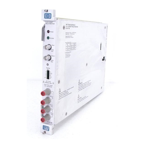
Input Terminals There are four input terminals on the faceplate of the multimeter
(see Figure 2-7 on page 29). The terminals, which are isolated from chassis
ground, are used to connect input signals when the multimeter is used
stand-alone.
A high-to-low TTL pulse applied to the External Trigger port externally
triggers the multimeter. The Analog Bus and Digital Bus ports allow relay
and FET multiplexers to be connected to the multimeter.
Chapter 1 Getting Started with the HP E1326B/E1411B Multimeter 15
Artisan Technology Group - Quality Instrumentation ... Guaranteed | (888) 88-SOURCE | www.artisantg.com
Introduction to Operation
This section contains information on checking communication between the
multimeter, mainframe, and computer. It includes information on returning
the multimeter to a known operating state should programming errors occur
or if you simply want to start over. It also shows how to send a command to
configure the multimeter and make a measurement.
Note The HP E1411B has a "Failed" annunciator and an "Access" annunciator on
the faceplate. The "Failed" annunciator turns on if the multimeter does not
properly respond during the mainframe’s power-on sequence. If this
occurs, return the multimeter to Hewlett-Packard for service. The "Access"
annunciator turns on each time the multimeter receives a command.
Multimeter Self-Test Once the mainframe completes its power-on sequence, the multimeter is
ready for use. Sending the self-test command is an easy way to verify that
you are properly addressing the multimeter. Also, the self-test is useful in
locating intermittent problems that might occur during operation. The
command used to execute the self-test is:
*TST?
You can also run the self-test by selecting “TEST” from the multimeter’s
front panel menu on the HP E1301A mainframe. Upon execution, the
self-test resets the multimeter, performs the test, and returns one of the
codes listed in Table 1-2.
The following program executes the self-test. The program assumes the
mainframe (command module for C-size systems) is at primary HP-IB
address of 09 and the multimeter is at secondary address 03. The program
also assumes an HP 9000 Series 200/300 computer is used.
10 !Send the self-test command to the multimeter.
20 OUTPUT 70903;"*TST?"
30 !Enter and display the self-test code.
40 ENTER 70903;A
50 PRINT A
60 !Reset the multimeter.
70 OUTPUT 70903;"*RST"
80 END
After the test passes, always reset the multimeter to return it to a known state.
16 Getting Started with the HP E1326B/E1411B Multimeter Chapter 1
Artisan Technology Group - Quality Instrumentation ... Guaranteed | (888) 88-SOURCE | www.artisantg.com

Table 1-2. HP E1326/E1411 Self-Test Codes
Self-Test
Code Description
0 Test passed.
1 Multimeter does not respond to the self-test.
2Invalid communication between the multimeter’s two on-board processors.
3 Data line test between the multimeter and the mainframe command module failed.
4 Invalid communication between the multimeter and mainframe command module.
If self-test code 1, 2, 3, or 4 occurs, return the multimeter to Hewlett-Packard for repair.
Note If the multimeter did not respond to the self-test, the address you specified
may be incorrect. Refer to Chapter 2 in this manual and the HP VXIbus
Systems Installation and Getting Started Guide.
Resetting the
Multimeter During operation, programming errors and other conditions may occur
making it necessary to reset the multimeter. This section shows you how to
reset and clear the multimeter, and read its error queue.
The multimeter is reset with the command:
*RST
which can be sent from an HP 9000 Series 200/300 computer as:
OUTPUT 70903;"*RST"
The multimeter can also be reset by pressing the green “Reset Instr” key on
the HP E1301A mainframe front panel. Note that the multimeter must first
be selected from the mainframe menu.
When resetting the multimeter:
•A front panel reset (“Reset Instr” key on the HP E1301A mainframe)
returns the multimeter to the idle state from the busy state and sets the
multimeter’s power-on configuration (Table 1-3). A front panel reset is
equivalent to clearing the multimeter followed by a reset.
•A reset from the computer (*RST) returns the multimeter to the idle
state from the busy state if the multimeter is busy due to a command
entered from the front panel. If the multimeter is busy due to a
command sent from the computer, you must clear the multimeter
before sending the reset. The reset sets the multimeter’s power-on
configuration.
Chapter 1 Getting Started with the HP E1326B/E1411B Multimeter 17
Artisan Technology Group - Quality Instrumentation ... Guaranteed | (888) 88-SOURCE | www.artisantg.com
Table 1-3. HP E1326/E1411 Power-on Settings
Parameter Setting
FUNCtion VOLT:DC
VOLTage:RANGe 8V
RESistance:RANGe 16384Ω
VOLTage:RANGe:AUTO ON
RESistance:RANGe:AUTO ON
VOLTage:RESolution 7.629 µV
RESistance:RESolution 15.6 mΩ
VOLTage:APERture 16.7 ms or 20 ms (based on line frequency)
RESistance:APERture 16.7 ms or 20 ms (based on line frequency)
CALibration:LFRequency Unchanged (factory setting = 60 Hz)
VOLTage:NPLC 1
RESistance:NPLC 1
RESistance:OCOMpensated OFF
CALibration:ZERO:AUTO ON
TRIGger:COUNt 1
TRIGger:DELay:AUTO ON
TRIGger:SOURce IMM
SAMPle:COUNt 1
SAMPle:SOURce IMM
18 Getting Started with the HP E1326B/E1411B Multimeter Chapter 1
Artisan Technology Group - Quality Instrumentation ... Guaranteed | (888) 88-SOURCE | www.artisantg.com
Clearing the Multimeter When the multimeter is selected from the HP E1301A mainframe menu, the
multimeter is cleared by pressing the “Clear Instr” key on the front panel.
The multimeter is also cleared by sending the following command from an
HP 9000 Series 200 or Series 300 controller:
CLEAR 70903
Clearing the multimeter:
–allows you to regain control without cycling power and without
setting the power-on configuration.
–with the HP E1301A “Clear Instr” key terminates any
command entered from the front panel. A command sent from
the computer will still continue to execute.
–from the computer (CLEAR 70903) terminates any command
sent from the computer. A command entered from the
HP E1301A front panel will still continue to execute.
–erases any pending commands. For example, if commands are
sent from the computer to the multimeter while the multimeter is
waiting for an external trigger, the commands are buffered until
they can execute after the trigger is received. Clearing the
multimeter (from the computer) erases those commands.
Similarly, clearing the multimeter from the HP E1301A front
panel erases any pending front panel commands.
–if cleared from the HP E1301A front panel, the display buffer is
cleared. If cleared over HP-IB, the data in the output buffer is
erased.
The Error Queue When an error occurs during operation, an error code and corresponding
message are stored in the multimeter’s error queue. If the Series B
mainframe has a display (HP E1301A) and the multimeter is being
monitored, the "err" annunciator will turn on.
Since many mainframes may not have a front panel display, the other way
to determine if an error has occurred is to read the error queue. This is done
with the command:
SYSTem:ERR?
The following program shows how the command is used to read and clear
the error queue.
10 !Declare a string variable in the computer to store the error message.
20 DIM Message$[256]
30 !Read the error queue until no errors remain.
40 !Print the error codes and messages.
50 REPEAT
60 OUTPUT 70903;"SYST:ERR?"
70 ENTER 70903;Code,Message$
80 PRINT Code,Message$
90 UNTIL Code=0
100 END
Chapter 1 Getting Started with the HP E1326B/E1411B Multimeter 19
Artisan Technology Group - Quality Instrumentation ... Guaranteed | (888) 88-SOURCE | www.artisantg.com
This manual suits for next models
1
Table of contents
Other HP Multimeter manuals