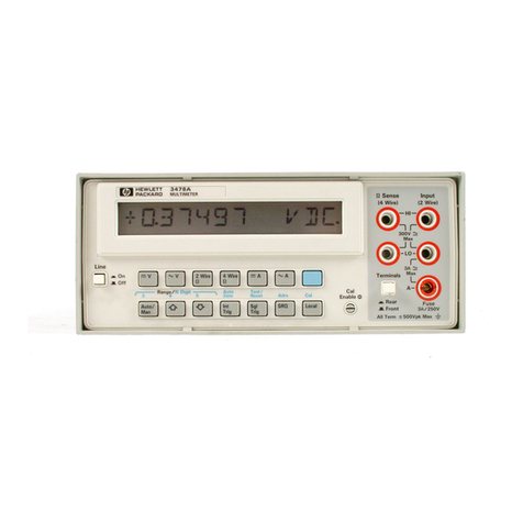
HP 3478A User manual

TM 11-6625-3071-14
TECHNICAL MANUAL
OPERATOR’S ORGANIZATIONAL, DIRECT SUPPORT,
AND GENERAL SUPPORT MAINTENANCE MANUAL
DILGITAL MULTIMETER
HEWLETT - PACKARD MODEL 3478A
HEADQUARTERS, DEPARTMENT OF THE ARMY 5 MARCH 1985

TM 11-6625-3071-14
A

TM 11-6625-3071-14
hp-HEWLETT
PACKARD
SAFETY SUMMARY
The following general safety precautions must be observed during all phases of operation, service, and repair of
this instrument Failure to comply with those precautions or with specific warnings elsewhere in this manual
violates safety standards of design, manufacture, and intended use of the instrument Hewlett Packard Company
assumes no liability for the customer’s failure to comply with these requirements. This is a Safety Class 1
instrument
GROUND THE INSTRUMENT
To minimize shock hazard, the instrument chassis and cabinet must be connected to an electrical ground. The instrument
is equipped with a three-conductor ac power cable. The power cable must either be plugged into an approved three-
contact electrical outlet or used with a three-contact to two-contact adapter with the grounding wire (green) firmly
connected to an electrical ground (safety ground) at the power outlet. The power jack and mating plug of the
power cable meet International Electrotechnical Commission (IEC) safety standards.
DO NOT OPERATE IN AN EXPLOSIVE ATMOSPHERE
Do not operate the instrument in the presence of flammable gases or fumes. Operation of any electrical instrument in such
an environment constitutes a definite safety hazard.
KEEP AWAY FROM LIVE CIRCUITS
Operating personnel must not remove instrument covers. Component replacement and internal adjustments must be
made by qualified maintenance personnel. Do not replace components with power cable connected. Under certain
conditions, dangerous voltages may exist even with the power cable removed. To avoid injuries, always disconnect power
and discharge circuits before touching them.
DO NOT SERVICE OR ADJUST ALONE
Do not attempt internal service or adjustment unless another person, capable of rendering first aid and resuscitation, is
present.
DO NOT SUBSTITUTE PARTS OR MODIFY INSTRUMENT
Because of the danger of introducing additional hazards, do not install substitute parts or perform any unauthorized
modification to the instrument. Return the instrument to a Hewlett- Packard Sales and Service Office for service and repair
to ensure that safety features are maintained.
DANGEROUS PROCEDURE WARNINGS
Warnings, such as the example below, precede potentially dangerous procedures throughout this manual. Instructions
contained in the warnings must be followed.
Dangerous voltages, capable of causing death, are present in this instrument Us ex-
treme caution when handling, testing, and adjusting.
B

TM 11-6625-3071-14
C/ (D BLANK)

TM 11-6625-3071-14
This manual contains copyright material reproduced by permission of the Hewlett-N Packard Company, Valley Forge, PA
19482.
Technical Manual) HEADQUARTERS)
DEPARTMENT OF THE ARMY
No. 11-6625-3071-14 ) Washington, DC, 5 March 1985
OPERATOR’S, ORGANIZATIONAL
DIRECT SUPPORT, AND GENERAL SUPPORT
MAINTENANCE MANUAL
DIGITAL MULTIMETER HP MODEL 3478A
Serial Numbers: 2136A00101 and Greater
IMPORTANT NOTICE
If the Serial Number of your instrument is lower than the one
on this title page, the manual contains revisions that do not
apply to your instrument. Backdating information given in
the manual adapts it to earlier instruments.
Where practical, backdating information is integrated into
the text, parts list and schematic diagrams. Backdating
changes are denoted by a delta sign. An open delta (a) or
lettered delta (AA) on a given page, refers to the
corresponding backdating note on that page.
REPORTING ERRORS AND RECOMMENDING IMPROVEMENTS
You can help improve this manual. If you find any mistakes or if
you know of a way to improve the procedures, please let us
know. mail your letter, DA Form 2028 (recommended Changes
to Publications and Blank Forms), or DA Form 2028-2 located in
the back of this manual direct to: Commander, US Army
Communications-Electronics Command and Fort Monmouth,
ATTN: DRSEL-ME-MP, Fort Monmouth, NJ 07703-5007.
In either case, a reply will be furnished direct to you.
i

TM 11-6625-3071-14
TABLE OF CONTENTS
Section Page
0. INTRODUCTION
0-1. Scope .............................................................................................................................................0-1
0-2. Consolidated Index of Army Publications and Blank Forms...........................................................0-1
0-3. Maintenance Forms, Records, and Reports...................................................................................0-1
0-4. Reporting Equipment Improvement Recommendations (EIR).......................................................0-1
0-5. Administrative Storage...................................................................................................................0-1
0-6. Destruction of Army Electronics Materiel........................................................................................0-1
ii

TM 11-6625-3071-14
TABLE OF CONTENTS
Section Page
I. GENERAL INFORMATION...........................1-1
1-1. Introduction.......................................1-1
1-3. Section I, General Information..........1-1
1-5. Section II, Installation Procedures....1-1
1-7. Section III, Operation........................1-1
1-9. Section IV, Performance Test and
Calibration 1-1
1-11. Section V, Replaceable Parts...........1-1
1-13. Section VI, Backdating.....................1-1
1-15. Section VII, Service..........................1-1
1-17. Appendix A.......................................1-1
1-19. Description........................................1-1
1-22. Specifications...................................1-1
1-24. Instrument and Manual
Identification......................................1-1
1-27. Options.............................................1-2
1-29. Accessories Available.......................1-2
Section Page
II. INSTALLATION.............................................2-1
2-1. Introduction.......................................2-1
2-3. Initial Inspection................................2-1
2-5. Power Requirements........................2-1
2-7. Line Frequency and Line
Voltage Selection..............................2-1
2-9. Power Cords and Receptacles.........2-2
2-11. Grounding Requirements.................2-1
2-13. Bench Use and Rack Mounting........2-2
2-14. Bench Use........................................2-2
2-16. Rack Mounting..................................2-3
2-18. HP-IB Interface Connections............2-3
2-21. Address Selection.............................2-3
2-24. Environmental Requirements...........2-3
2-25. Operating and Storage
Temperature.....................................2-3
2-27. Repackaging for Shipment...............2-4
Section Page
III. OPERATION.................................................3-1
3-1. Introduction.......................................3-1
3-4. General Information..........................3-1
3-5. AC Power Operation.........................3-1
3-7. Turn-On............................................3-1
3-10. Display..............................................3-1
3-12. Input Terminals.................................3-3
3-15. Input Terminals Cleaning..................3-3
3-17. Front Panel Operation......................3-3
3-18. DC Volts Measurements...................3-3
3-22. AC Volts Measurements...................3-4
3-26. Resistance Measurements...............3-4
3-30. DC Current Measurements...............3-5
3-34. AC Current Measurements...............3-5
3-38. Ranging............................................3-5
3-43. Triggering.........................................3-5
3-50. Shifted Operation..............................3-6
3-51. General.............................................3-6
3-54. Number of Digits Displayed..............3-6
3-57. Autozero...........................................3-7
3-60. Self-Test/Reset Operation................3-7
3-63. Calibration........................................3-7
3-66. Miscellaneous Operations................3-8
3-67. Voltmeter Complete ........................3-8
3-69. Remote Operation............................3-8
3-70. General.............................................3-8
3-74. 3478A Response to Bus Messages.3-8
3-92. 3478A Addressing............................3-10
3-96. Talk-Only Mode (No Controller).......3-10
3-98. 3478A HP-IB Programming..............3-11
3-117.Advanced Programming...................3-14
Section Page
IV. PERFORMANCE TEST AND
CALIBRATION..............................................4-1
4-1. Introduction.......................................4-1
4-4. Equipment Required.........................4-1
4-6. DC Volts Test and Calibration..........4-1
4-10. AC Volts Test and Calibration .........4-2
4-12. Ohms Test and Calibration..............4-2
4-15. DC Current Test and Calibration......4-3
4-20. AC Current Test and Calibration......4-3
4-24. Test Cards........................................4-3
4-26. Calibration Cycle..............................4-3
4-28. Test Failure .....................................4-3
4-30. Instrument Set-Up............................4-3
4-32. Instrument Specification...................4-3
4-35. Specification Breakdown .................4-4
4-39. Temperature Coefficient
(Reference Temperature)................4-4
4-41. Test Consideration...........................4-4
4-42. General.............................................4-4
4-44. Ambiguous Region...........................4-4
4-47. Performance Test.............................4-5
4-49. DC Volts Test...................................4-5
4-54. DC Current Test...............................4-7
4-59. AC Volts Test...................................4-8
4-64. AC Current Test...............................4-9
4-69. Ohms Test.4-10...............................4-10
4-76. Combined Calibration and
Performance Tests...........................4-11
4-77. General.............................................4-11
4-80. Calibrating the 3478A.......................4-12
4-82. Calibration Messages.......................4-13
4-84. Calibration Procedures.....................4-13
4-86. DC Volts Calibration and Test..........4-13
4-90. DC Current Calibration and Test......4-15
4-94. AC Volts Calibration and Test..........4-16
4-99. AC Current Calibration and
Test (Optional................................... 4-18
4-103.Ohms Calibration and Test..............4-18
iii

TM 11-6625-3071-14
TABLE OF CONTENTS (Cont’d)
Section Page
V. REPLACEABLE PARTS...............................5-1
5-1.Introduction....................................................5-1
5-4.Ordering Information......................................5-1
5-6.Non-Listed Parts............................................5-1
5-8.Parts Changed...............................................5-1
5-10.Propriety Parts...............................................5-1
5-12.3478a Disassembly Procedure......................5-2
Section Page
VI. BACKDATING...............................................6-1
6-1. Introduction.......................................6-1
Section Page
VII. SERVICE.......................................................7-1
7-1.Introduction....................................................7-1
7-3.Safety Consideration.....................................7-1
7-8.Recommended Test Equipment
7-10.Miscellaneous Information.............................7-1
7-11.Instrument Disassembly
(PC Board Replacement)........................................7-1
7-13.Fuse Replacement........................................7-1
Section Page
7-15.Troubleshooting.............................................7-2
7-16.Introduction....................................................7-2
7-18.3478A Self-Test.............................................7-2
7-27.Service Group Selection................................7-2
Service Groups....................................................Page
ADC Volts and DC Current
Troubleshooting......................................7-A-1
BAC Volts and AC Current
Troubleshooting.....................................7-B-1
COhms Troubleshooting...............................7-C-1
DA/D Converter and Logic
Troubleshooting......................................7-D-1
EPower Supplies and Reference
Troubleshooting.....................................7-E-1
FTheory of Operation....................................7-F-1
Schematics.......................................7-G-1/7-G-2
APPENDIX A......................................................A-1
B. References.......................................B-1
C. Components of End Item
List....................................................C-1
D. Additional Authorization
List(Not Application:)
E. Maintenance Allocation....................E-1
F. Expendable Supplies and
Material List(N/A)
LIST OF TABLES
Tables Page
3-1.Shifted Operations.........................................3-6
3-2.3478A Error Messages..................................3-7
3-3.3478A Bus Capabilities..................................3-8
3-4.Status Byte Definitions...................................3-10
3-5.3478A Address Codes...................................3-11
3-6.3478A Program Codes..................................3-12
3-7.Binary Status Byte Definition.........................3-14
4-1.Abbreviated Specifications Table..................4-1
4-2.Recommended Test Equipment....................4-2
4-3.DC Volts Test Limits......................................4-5
4-4.DC Current Test Limits..................................4-7
4-5.AC Volts Test Limits......................................4-8
4-6.AC Current Test Limits..................................4-9
4-7.Ohms Test Limits..........................................4-10
Tables Page
4-8.DC Volts Calibration and Test.......................4-13
4-9.DC Current Calibration and Test...................4-15
4-10.AC Volts Calibration and Test.......................4-17
4-11.AC Current Calibration and Test...................4-18
4-12.Ohms Calibration and Test...........................4-19
5-1.Standard Abbreviations.................................5-1
5-2.Code List of Manufacturers...........................5-2
5-3.Replaceable Parts List..................................5-3
5-4.3478A Mechanical and
Miscellaneous Parts......................................5-9
7-1.3478A Service Groups .................................7-2
7-F-1.Ohms Current and Ranges ..........................7-F-7
7-F-2. AC Amplifier ................................................7-F-9
A-1. 3478A Device Capability ..............................A-3
A-2.HP-IB Worksheet..........................................A-4
iv

TM 11-6625-3071-14
LIST OF ILLUSTRATIONS
Figure Page
2-1. Line Frequency Switch ....................2-1
2-2. Line Select Jumper ..........................2-2
2-3. Power Cords ....................................2-2
2-4. Typical HP-IB System
Interconnection ................................2-3
2-5. HP-IB Connector .............................2-4
2-6. 3478A Address Switch .....................2-4
3-1. 3478A Front and Rear Panel
Features ..........................................3-2
3-2. Typical Input Measurement
Connection .......................................3-3
3-3. Typical Current Measurement
Connection .......................................3-3
3-4. Ohms Connections ..........................3-4
3-5. Autoranging Points ..........................3-6
3-6. Status Byte .....................................3-9
4-1. Ambiguous Regions ........................4-4
4-2. DC Volts Accuracy Test
and Calibration .................................4-6
4-3. DC Common Mode Rejection Test...4-7
4-4. DC Current Accuracy Test
and Calibration .................................4-8
4-5. AC Current Accuracy Test
and Calibration .................................4-10
4-6. 4-Wire Ohms Short ..........................4-11
4-7. 4-Wire Ohms Connection ................4-11
5-1. 3478A Front Panel View 5-9/5-10
5-2. 3478A Rear Panel View 5-9/5-10
5-3. 3478A Bottom View . 5-9/5-10
5-4. 3478A Left Side View 5-9/5-10
5-5. Bottom View With
Cover Removed ...............................5-11
5-6. Top View With
Cover Removed................................5-11
5-7. Front Panel Bracket View ................5-11
5-8. Front Panel Assembly ......................5-11
7-A-1.JM403 SA Connection .....................7-A-4
7-B-1. JM403 SA Connection .....................7-B-2
7-C-1.JM403 SA Connection. ....................7-C-4
7-D-1. US01 ALE Signal .............................7-D-2
7-D-2.Flowchart A.......................................7-D-3
Figure Page
7-D-3. Flowchart B......................................7-D-5
7-D-4. Flowchart C .....................................7-D-6
7-D-5. U462 ALE Signal .............................7-D-8
7-D-6. Flowchart D .....................................7-D-9
7-D-7. JM403 SA Connection.....................7-D-10
7-F-1. 3478A Simplified Block
Diagram ...........................................7-F-2
7-F-2. Simplified Schematic of the
Input Switching Circuitry ..................7-F-4
7-F-3. Simplified Schematic of the
DC/Ohms Input Amplifier ................7-F-6
7-F-4. Ohms Circuitry Configuration ..........7-F-6
7-F-5. AC Gain Configurations ...................7-F-8
7-F-6. Dual Slope Conversion ....................7-F-9
7-F-7. Simplified A/D Converter ..............7-F-10
7-F-8. Integrator (U401) Output
Slopes ..........................................7-F-10
7-F-9. Runup Slopes
(4 1/2 Digit Model) ........................7-F-11
7-F-10. Runup Slopes For Zero Inputs
4 1/2 Model) .................................7-F-12
7-F-11. Slope S + 4 Generation ................7-F-12
7-F-12. Slope S - 4 Generation .................7-F-12
7-F-13. Slope S+0 and S-0
Generation ....................................7-F-13
7-F-14. Rundown Slopes ..........................7-F-13
7-F-15. Determining the DAC Setting .......7-F-15
7-F-16. A/D Hybrid (U403) ........................7-F-15
7-F-17. 3478A Simplified Reference
Circuitry ........................................7-F-16
7-F-18. Power-On Circuitry .......................7-F-17
7-F-19. Reset Circuitry ..............................7-F-18
7-G-1. General Schematic Notes ...............7-G-1
7-G-2. 3478A Block Diagram .....................7-G-3
7-G-3. Input Circuitry and
Ohms Current Source 7-G-5/7-G-6
7-G-4. AC to DC Converter ........................7-G-7
7-G-5. A/D Converter and
Control Logic ......................7-G-9/7-G-10
7-G-6. Power Supplies ...............7-G-11/7-G-12
A-1. Interface Connection and
Bus Structure...............................A-2
v

TM 11-6625-3071-14
SECTION 0
INTRODUCTION
0-1. SCOPE
This manual describes the Digital Multimeter, HP Model 3478A and provides instructions for operation and maintenance.
0-2. CONSOLIDATED INDEX OF ARMY PUBLICATIONS AND BLANK FORMS
Refer to the latest issue of DA Pam 310-1 to determine whether there are new editions, changes or additional publications
pertaining to the equipment.
0-3. MAINTENANCE FORMS, RECORDS, AND REPORTS
a. Reports of Maintenance and Unsatisfactory Equipment. Department of the Army forms and procedures used for
equipment maintenance will be those prescribed by DA Pam 738-750, as contained in Maintenance Management
Update.
b. Report of Packaging and Handling Deficiencies. Fill out and forward SF 364 (Report of Discrepancy (ROD)) as
prescribed in AR 735-11-2/DLAR 4140.55/ NAVMATINST 4355.73A/AFR 400-54/MCO 4430.3F.
c. Discrepancy in Shipment Report (DISREP)(SF 361). Fill out and forward Discrepancy in Shipment Report
(DISREP)(SF 361) as prescribed in AR 55-38/ NAVSUPINST 4610.33C/AFR 75-18/MCO P4610.19D/DLAR
4500.15.
0-4. REPORTING EQUIPMENT IMPROVEMENT RECOMMENDATIONS (EIR)
If your equipment needs improvement, let us know. Send us an EIR. You, the user, are the only one who can tell us what
you don’t like about your equipment. Let us know why you don’t like the design. Put it on an SF 368 (Quality Deficiency
Report). Mail it to Commander, US Army Communications-Electronics Command and Fort Monmouth, ATTN: DRSEL-ME-
MP, Fort Monmouth, NJ 07703-5007. We’ll send you a reply.
0-5. ADMINISTRATIVE STORAGE
Administrative storage of equipment issued to and used by Army activities will have preventive maintenance performed in
accordance with the PMCS charts for storing. When removing the equipment from administrative storage the PMCS
should be performed to assure operational readiness. Disassembly and repacking of equipment for shipment or limited
storage is covered in paragraph 2-27.
0-6. DESTRUCTION OF ARMY ELECTRONICS MATERIEL
Destruction of Army electronics materiel to prevent enemy use shall be in accordance with TM 750-244-2.
0-1

TM 11-6625-3071-14
SECTION I
GENERAL INFORMATION
The information in this manual is for the use of Service
Trained Personnel. To avoid electrical shock, do not
perform any procedures in the manual or do any
servicing to the 3478A unless you are qualified to do so.
1-1. INTRODUCTION
1-2. The information in this manual is for the Install
tion, Operation, Performance, Calibration, and Service of
the 3478A Digital Multimeter. The manual is designed for
the use of Service Trained Personnel. Other use should
refer to the Operators Manual. This manual separated
into the following sections.
1-3. Section I, General Information
1-4. A short description of the manual and
introduction to the 3478A is in Section 1. The section
also lists instrument options, specifications, and
accessories.
1-5. Section II, Installation Procedures
1-6. This section explains how the 3478A is prepare
for use and includes power requirements, line voltage
selection, etc. The section also explains how to connect
the multimeter for remote operation.
1-7. Section III, Operation
1-8. The condensed operating instructions of 3478A,
for the use of Service Trained Personnel, is this section.
For more complete instructions, refer to Operators
Manual.
1-9. Section IV, Performance Test and Calibration
1-10. The 3478A’s Performance Test and Calibration
Procedures are in Section IV. The Required Equipment
Table and an abbreviated specification table are also
included.
1-11. Section V, Replaceable Parts
1-12. Section V lists the replaceable parts of the 3478t
It also includes pictures and illustrations of chassis and
mechanical parts.
1-13. Section VI, Backdating
1-14. This section has information which adapts this
manual to 3478A’s with serial numbers below the ones
shown on the title page.
1-15. Section VII, Service
1-16. The 3478A’s Troubleshooting Procedures,
Theory Of Operation, and Schematics are in Section VII.
The troubleshooting information is in the form of Service
Groups which are symptoms oriented (i.e., what is the
failure). The complete theory of operation is in Service
Group F and the Schematics are in Service Group G
(last group).
1-17. Appendix A
1-18. The appendix has a condensed description of
the HP-IB (Hewlett-Packard Interface Bus).
1-19. DESCRIPTION
1-20. The -hp- Model 3478A is a versatile multimeter
with dc and ac volts, dc and ac currents, and resistance
measurement capabilities. The multimeter is excellent for
bench use, and since it is remotely programmable, it can
be used in measurement systems. A feature of the
instrument is that the reading can be displayed in either 5
1/2, 4 1/2, or 3 1/2 digits. Other features are Autozero
(for good stability), and an Alphanumeric Liquid Crystal
Display.
1-21. Another excellent feature is Electronic
Calibration. No mechanical adjustments are necessary to
calibrate the 3478A.
1-22. SPECIFICATIONS
1-23. Specifications of the 3478A are the performance
characteristics of the multimeter which are certified. The
specifications are listed in Table 1-1 and Table 4-1 (in
Section IV). They are the performance standards or
limits against which the multimeter can be tested.
1-24. INSTRUMENTANDMANUAL IDENTIFICATION
1-25. Instrument Identification is by a serial number
located on the multimeter’s rear panel. Hewlett-Packard
uses a two-part serial number, with the first part (prefix)
identifying a series of instruments and the
1-1

TM 11-6625-3071-14
Table 1-1. Specification
1-2

TM 11-6625-3071-14
Table 1-1. Specifications. Cont.
1-3

TM 11-6625-3071-14
Table 1-1. Specifications. Cont.
1-4

TM 11-6625-3071-14
3478A
second part (suffix) identifying a particular instrument
within a series. An -hp- assigned alpha character l
between the prefix and suffix identifies the country which
the 3478A was manufactured.
1-26. This manual applies to instruments with the
serial number identified on the title page. Updating of the
manual is accomplished either by a change sheet
revised manual.
1-27. OPTIONS
1-28. The following options are available for the
3478A.
Option 315: set for 100V, 50Hz Power Source
Option 316: set for 100V, 60Hz Power Source
Option 325: set for 120V, 50OHz Power Source
Option 326: set for 120V, 60Hz Power Source
Option 335: set for 220V, 50Hz Power Source
Option 336: set for 220V, 60Hz Power Source
Option 345: set for 240V, 50OHz Power Source
Option 346: set for 240V, 60Hz Power Source
Option 907: Front Handle Kit (-hp- Part No.
5061-1088)
Option 908: Rack Mount Kit includes one rack flange
and one extension adapter (-hp- Part No. 5061-0072)
Option 910: additional set of Operators and Service
Manuals.
1-29. ACCESSORIES AVAILABLE
1-30. The following is a list of available accessories for
the 3478A.
Accessory No. Descri
ption
10023A Temperature Probe
10631A HP-IB Cable 1 meter (39.37 in)
10631B HP-IB Cable 1 meter (78.74 in)
10631C HP-IB Cable 1 meter (157.48 in)
10631D HP-IB Cable 1 meter (19.69 in)
11000A Test leads, dual banana both
ends
11002A Test leads, dual banana to dual
alligator
11003A Test leads, dual banana to
probe and alligator
11096B RF Probe
34111A High Voltage Probe
34118A Test leads, dual banana to
probes with Safety Guard Rings
1-5/(1-6 blank)

TM 11-6625-3071-14
SECTION II
INSTALLATION
2-1. INTRODUCTION
2-2. This section of the manual has the necessary
information and instructions to install and interface the -hi
Model 3478A Digital Multimeter. Included are initial
inspection procedures, power requirements,
environmental information, and instructions for repacking
the instrument for shipment. The information in this
section is for Service Trained Personnel.
The information in this manual is for the use of
Service Trained Personnel. To avoid electrical shock, do
not perform any procedures in this manual or do any
servicing to the 3478A unless you are qualified to do so.
2-3. INITIAL INSPECTION
2-4. The 3478A was carefullyinspected bot
mechanicallyand electricallybefore shipment. It should
be free of mars or scratches and in perfect electric; order
upon receipt. The multimeter should be inspected for any
damage that mayhave occurred in transit. If the shipping
container or cushioning material is damaged, should be
kept until the contents of the shipment haybeen checked
for completeness and the instrument ha been
mechanicallyand electricallychecked. Procedure for
checking the electrical performance of the 3478A al in
Section IV. If there is mechanical damage, the cot tents
are incomplete, or the multimeter does not pass the
Performance Test, notifythe nearest Hewlett-Packard
office (a list of the -hp-Sales/Service offices is located i
the back of the manual). If the shipping container
damaged or the cushioning material shows signs C
stress, notifythe carrier as well as the Hewlett-Packard
office. Save the shipping material for the carrier’s
inspection.
2-5. POWER REOUIREMENTS
2-6. The 3478A requires a power source of 100V,
120w 220V, or 240V ac (- 10%, + 5%), 48Hzto 440Hz
sing phase. The maximum power consumption is 25VA.
For the 3478A to meet its noise and normal mode
rejection specifications, the multimeter must be operated
using line frequencyof either 50Hzor 60Hz(dependent
on instrument option). A listing of the 3478A’spower
options, the corresponding power line voltages and
frequencies, and fuses are as follows:
Option Voltage and Frequency Fuse
Option 315 100V ac @ 50Hz 250mA
Option 316 100V ac @ 60Hz 250OmA
Option 325 120V ac @ 50Hz 250mA
Option 326 120V ac @ 60Hz 250mA
Option 335 220V ac @ 50Hz 125mA
Option 336 220V ac @ 60Hz 125mA
Option 345 240V ac @ 50Hz 125mA
Option 346 240V ac @ 60Hz 125mA
CAUTION
Before connecting power to the
3478A,make sure the power source
matches the power requirements of the
multimeter, as marked on the rear panel
(below the power receptacle). If the
instrument is incompatible with the
available power source, go to paragraph
2-7 to reconfigure the multimeter.
2-7. Line Frequency and Line Voltage Selection
To avoid electrical shock and personal
in- jury, make sure the multimeter is
disconnected from its external power
voltage source before removing any
covers.
2-8. The Power Line Frequencyconfiguration of the
3478A is done bythe 8 section "DIP" switch at the
multimeter’srear panel. Locate the switch (shown in
Figure 2-1) and set the switch to the desired power
frequency(50Hzor 60Hz), as shown in the figure. Toset
the 3478A’s correct line voltage, perform the following
Figure 2-1. Line Frequency Switch
2-1

TM 11-6625-3071-14
a.Loosen the screw on the rear of the 3478A’s top
cover and remove the cover.
b.Locate the Line Select wire and the line
terminals. The wire and terminals are located near the
3478A’s power transformer (see Figure 2-2).
c. Refer to Figure 2-2 and connect the wire to the
line terminal which corresponds to the desired line
voltage.
Figure 2.2. Line Select Jumper
d.After changing the Line Voltage, mark the 3478A’s
rear panel to reflect the voltage change (mark the little
box under the instrument’s power cord receptacle that
corresponds to the new line voltage).
e.Reinstall the top cover.
2-9. POWER CORDS AND RECEPTACLES
2-10. Figure 2-3 illustrates the different power plug
configurations that are available to provide power to the
3478A. The -hp- part number shown directlybelow the
individual power plug drawing, is the part number for the
power cord set equipped with the appropriate mating
plug for that receptacle. If the appropriate power cord is
not included with the instrument, notifythe nearest -hp-
Sales/Service office and a replacement will be provided.
2-11. GROUNDING REOUIREMENTS
2-12. Toprotect operating personnel, the National
Electrical Manufacturing Association (NEMA)
recommendation is to ground the instrument panel and
cabinet. The 3478A is equipped with a three conductor
power cable which, when plugged into an appropriate
receptacle, grounds the instrument.
2-13. BENCH USE AND RACK MOUNTING
2-14. Bench Us
2-15. The 3478A is equipped with feet and tilt stands
installed and is ready for use as a bench instrument. The
Figure 2-2. Line Select Jumper
Figure 2-3. Power Cords
2-2

TM 11-6625-3071-14
3478A
feet are shaped to permit stacking with other half-
module Hewlett-Packard instruments.
2-16. Rack Mounting
2-17. The 3478A may be rack mounted by adding rack
mounting kit Option 908. The basic hardware and
instructions for rack mounting is contained in the kit. The
kit is designed to permit the 3478A to be mounted in a
standard 19 inch rack, provided that sufficient rear sup-
port is available.
2-18. HP-IB INTERFACE CONNECTIONS
2-19. The 3478A is compatible with the Hewlett-
Packard Interface Bus (HP-IB).
NOTE
HP-IB is Hewlett-Packard’s
implementation of IEEE Std. 488-1978,
"Standard Digital Interface For
Programmable Instrumentation" and
ANSI MC. 1.1.
2-20. The interface connection is made by an HP-IB
Interface Cable to the 24 pin HP-IB connector located at
the rear panel. A typical interconnection of an HP-IB
system is shown in Figure 2-4, in which ends of the
cables have both a male and female connector to enable
connections to other instruments and cables. As many
as 15 instruments can be connected to the same
interface bus. However, the maximum length of cable
that can effectively be used to connect a group of
instruments should not exceed 2 meters (6.56 ft.) times
the number of instruments connected, or 20 meters (65.6
ft.), whichever is less. For a pictorial view of the HP-IB
connector and its pin designation, refer to Figure 2-5.
2-21. ADDRESS SELECTION
2-22. 3478A Address.The HP-IB "talk" and "listen"
address of the 3478A is set by the multimeter’s address
switch (located at the rear panel). The talk and listen ad-
dress is a 5-bit code which is selected to provide a
unique address for each HP-IB instrument. The 3478A
normally leaves the factory with the address switch set to
Decimal Code "23". The corresponding ASCII Code is a
listen address code of "7" and a talk code of "W". Refer
to Figure 2-5 for the factory address setting of the switch.
Refer to the Remote Operation Chapter in Sec- tion III of
this manual, for more information on ad- dressing and
address codes.
2-23. 3478A Talk-Only Mode. The 3478A has a Talk-
Only Mode which is selected by the Address Switch. The
mode is selected by setting all the address switches
(switch 4 to 8) up (on). Refer to the Remote Operation
Chapter in Section III of this manual for more
information.
2-24. ENVIRONMENTAL REOUIREMENTS
To prevent electrical fire or shock
hazards, do not expose the instrument
to rain or excessive moisture.
2-25. Operating and Storage Temperature
2-26. To meet and maintain the specifications listed in
Table 1-1, the 3478A should be operated within + 5°C (±
9°F) of the Reference Temperature. The Reference
Temperature is the temperature in which the 3478A was
last calibrated. For example, if the last Reference
Temperature was 230C (73°F), the 3478A should main-
tain its specifications if operated within ± 5°C (± 9°F) of
that temperature. The factory temperature is from 18°C
to 280C (64°F to 82°F). The 3478A may be operated
within an ambient temperature range of 0°C to 55C (32°F
to 1310F) with less accuracy.
Figure 2-4. Typical HP-IB System Interconnection
2-3

TM 11-6625-3071-14
3478A
Figure 2-5. HP-IB Connector
2-27. REPACKAGING FOR SHIPMENT
NOTE
If the instrument is to be shipped to Hewlett-
Packard for service or repair, attach a tag to the
instrument identifying the owner and indicating
the required service or repair. Include the model
number and full serial number of the instrument.
In any correspondence, identify the instrument
by model number and full serial number. If you
have any questions, contact your nearest -hp-
Sales/Service office.
2-28. Place the instrument in its original container wit
appropriate packaging material and secure with strong
tape or metal bands. If the original container is not
available, a replacement can be obtained from you
nearest -hp- Sales/Service office. Hewlett-Packard
suggests that you always insure shipments.
Figure 2-6. 3478a Address Switch
2-29. If the original container is not to be used, do the
following:
a. Wrap the instrument in heavy plastic, before
placing in an inner container.
b. Place packing material around all sides of the
instrument and protect the front panel with cardboard
strips.
c. Place the instrument in the inner container in a
heavy carton. Seal the carton with strong tape or metal
bands.
d. Mark shipping container "DELICATE INSTRU-
MENT", "FRAGILE", etc.
2-30. WHERE TO SHIP YOUR UNIT FOR REPAIR
2-31. Inside the U.S.A.
For fast service, return the unit along with the service
card safely packaged directly to:
Hewlett-Packard
Instrument Service Center
P.O. Box 7922
890 Middlefield
Mountainview, CA 94042
2-32. Outside the U.S.A.
Return your unit to the nearest designated Hewlett-
Packard Sales and Service Office. Check the back of
this manual for the address. /7
2-4

TM 11-6625-3071-14
SECTION III
OPERATION
3-1. INTRODUCTION
3-2. This section has the information and
instructions for the operation of the 3478A Multimeter,
showing front panel and remote operation. The
information is an abbreviated description of the operation
and is written for a Service Trained Person, rather than
an Operator. For more complete operating instructions,
refer to the 3478A’s Operators Manual. To familiarize
yourself with the front and rear panel features or for a
review of instrument operations, refer to Figure 3-1.
3-3. The Operation Section is separated into the
following major areas: General Information, Front Panel
Operation, Shifted Operation, Miscellaneous Operation,
and Remote Operation (HP-IB). It is suggested that you
read the Remote Operation Chapters last, since you
need to know the other operations to understand the
remote operations. The major areas are as follows:
a. General Information - paragraph 3-4.
Title Paragraph
AC Power Operation 3-5
Turn-On 3-7
Display 3-10
Input Terminals 3-12
Input Terminals Cleaning 3-15
b. Front Panel Operation - paragraph 3-17.
Title Paragraph
DC Volts Measurements 3-18
AC Volts Measurements 3-22
Resistance Measurements 3-26
DC Current Measurements 3-30
AC Current Measurements 3-34
Ranging 3-38
Triggering 3-43
c. Shifted Operation - paragraph 3-50.
Title Paragraph
Number Of Digits Displayed 3-54
Autozero 3-57
Self-Test/Reset Operation 3-60
Calibration 3-63
d. Miscellaneous Operation - paragraph 3-66.
Title Paragraph
Voltmeter Complete 3-67
e. Remote Operation - paragraph 3-69.
Title Paragraph
General ......................................3-70
3478A Response to Bus
Messages...................................3-74
3478A Addressing......................3-92
Talk-Only Mode (No
Controller) ..................................3-96
3478A HP-IB Programming .......3-98
Advanced programming.............3-117
3-4. GENERAL INFORMATION
3-5. AC Power Operation
3-6. Before connecting ac power to the 3478A, make
sure the power source matches the power requirement
of the multimeter (as marked on the rear panel). If the
instrument is incompatible with the power source, refer to
Section II of this manual for power requirement
modification.
3-7. Turn-On
3-8. When the 3478A is first turned on, the
multimeter goes through an Internal Test routine. During
the test, a certain message or characters may be
displayed for abour l/4 second. When the test is
completed and the 3478A passes the test, the 3478A’s
remote (HP-IB) address will be displayed for about one
second. The address is displayed as "HPIB ADRS, dd",
where "dd" is the address code of the instrument. If the
Self-Test fails, refer to Section VII of this manual for
troubleshooting information. For more information on the
Self-Test, refer to paragraph 3-58.
3-9. Once the Self-Test is completed, the 3478A
goes to its turn-on state which is:
FUNCTION .............................................DCV
RANGE ...................................................AUTO
TRIGGER ...............................................INTERNAL
AUTOZERO ............................................ON
NUMBER OF DIGITS DISPLAYED.........5
3-10. Display
3-11. The Display is a 12 character alphanumeric
Liquid Crystal Display (LCD) with 12 annunciators. The
display is normally used to show readings, however, the
display can also show alphanumeric messages (sent
remotely). The four characters to the right show the
function (and to a certain extent, the range) and the 8
3-1
Other manuals for 3478A
4
Table of contents
Other HP Multimeter manuals