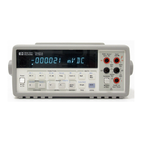
HP 3490A Service manual

HEWLE"WPACKARD
CE
RTI
FI
CATI
O
tII
TheHewlett-PaclnrdCompany
certifinsthat thisinstrammt was
thoroughly
tested,
ond.inspected
and fourd to meet its pu,blished
specifications
whm it was
shipped
lrom thefactorU.
TheHewlett-
Paclard Com,pany
further certifies tlmt its calibration rneo$re-
m,mts
are traceable
to the U.S.Natiornl Bureau
of Standards
to
tlrc ertmt allowedby the Brneau'scalibration
facility.
WARRA]TTY
ATD
ASSISTAITCE
All Hewlett-Packard
productsare warranted againstdefectsin
materials
andworkrnanship."'This
warrantyapplies
for oneyear
from the dateof delivery,
or, in'the caseof certainmajor compo-
nentslisted in the operatingmanual,
for thespecified
period.
We
will repairor replace
products
which
prove
to bedefective
during
thewarrantyperiod
provided
theyarereturned
to Hewlett-
Packard.
No otherwarranty is expressed
or implied.Weare not
liablefor consequential
damages.
Service
contracts
or customer
assistance
agreements
are available
for Hewlett-Packard
products
that requiremaintenance
and re-
pair on-site.
Forany
assistance,
contact
yournearest
Hewlett-Packard
Sales
and
Service
Office.Addresses
areprovided
at theback
of this manual.
Get other manuals https://www.bkmanuals.com

v
OPERATING
AITD
SERYICE
MAIIUAI
ManualPartNo.
03490-90014
MicrofichePartNo.03490-90064
MODEL
3490A
MUtTIM ETER
!;:,'
;.t; .:
:i;:
-:
!:.. '.
::::
"
Themain
body of thismanual
appliesto
SerialPrefix 1211A
Any changes
madein instruments
manufactured
after this
printing will be found in a "ManualChanges"
supplement
supplied with this manual. Be sure
.to examine this
supplement,
if oneexists
for thismanual,
for anychanges
whichapplyto your instrument
andrecord
these
changes
in
the manual.
Backdatinginformation
for instruments
manu-
factured
before
this printingwill be found in SectionVIII.
CopyrightHewlett-Pack
afi Company|972
P.O.
Box
301,
l,oveland,
Colorado 80537 U.S.A
Printed:
APRIL
1974
Get other manuals https://www.bkmanuals.com

Model3490A
TABLEOF
Section Page
I. GENERALINFORMATION... ......I-1
l-1. Introduction ...1-l
l-5. Specifications
.... .'-.l-l
l-8. Options -......1-1
l-10. AccessoriesSupplied ...1-l
l-12. AccessoriesAvailable ...1-1
l-14. Instrument
andManual
Identification ......1-2
Section Page
II. INSTALLATION
ANDINTERFACE
.... ... .2-I
2-l- Introduction ..-2-l
2-3. Initiallnspection.. ....2-l
2-5. PowerRequirements -..2-l
2-8. PowerCordsandReceptacles
.. -
.....2-l
2-10. GroundingRequirements...
...
.. .
-
..2-1
2-14. Environmental
Requirements
. . . . -. . .2-l
2-16. Installation ....2-2
2-17. BenchUse -...2-2
2-19. RackMounting.... .... -...2-2
2-21. Installationofoptions .... -...2-2
2-23. Isolated
DataOutPut
Option021
(-hp
lll2lA) .. ..... .2-2
2-25. IsolatedRemote
OPtionO22
(hpllr22{). ---..2-2
2-27. Option050andOption060
.. ..... -2-3
2-29. InterfaceConnections ...'....2-3
2-30. DataOutput
OPtion
021 .. . -2:2
2-32. RemoteControlOption
022..... -. -2-3
2-34. RearInput . . .24
2-36. General
Purpose
Interface
Bus
Connections ...'-..24
2-38. InterfaceCableLength ......2-6
24O Trigger
Connections,
GPIBOption030 .......2-8
242. Sample/Hold
Connections, -'-''
Option
UO|O4| ... ... . .2-8
246. RepackagingforShipment .....2-9
Section Page
Iil. OPERATING
INSTRUCTIONS.
. . .. ..3-I
3-1. Introduction ...3-1
3-3. InstrumentCapabilities --...'.3-l
3-4- Standardlnstrument ....'...3-1
3-6. Output andRemote
ControlOptions .3-l
3-9. Sample/Hold
Option
040or &15 . ' . .3-1
3-ll. RatioOption
080
.
. .. .. ..
..3-l
3-13. Front andRear
Panel
Description. -. . -3-l
3-15. MadmumlnputVoltages
...........3-l
3-17. GeneralOperatinglnstructions
.-... ..3-2
3-18. Turn-OnandWarm-Up ......3-2
3-20. Guarding .....3'2
3-24. FloatingMeasurements
..... ..... -.3-2
3-26. Overrange
Measurements
. . . . . . . . . -3-3
3-28. Overloadlndication ........3-3
3-30. Rangelndication
.. ...-....3-3
3-32. Functionlndication ........3-3
Table
ofContents
CONTENTS
Section
III (cont'd) Page
3-34. Autoranging ........3-3
3-36. ManualTrigger ......3-3
3-38. Self-TestOperation ....3-3
340. DCVoltageMeasurements
........... 3-3
342. DCSample
Rate
and
ResponseTime. ....34
344. InputResistance
.. . .. .. ... .34
346. ACVoltageMeasurements .....34
348. AC Sample
Rateand
ResponseTime. ....34
3-50. FrequencyRange. ...34
3-52. Inputlmpedance
.. ........34
3-54. HarmonicDistortion ........34
3-56. Resistance
Measurements
. . . . . . .. . . . .34
3-58. InputConnections
. ........3-5
3-60. Ohms
SignalVoltage
andCurrent. . . .3-5
3-62- Ohmmeter
Sample
Rateand
ResponseTime. ....3-5
3-64. ExternalTrigger
(Option020) . . .. . . . . 3-5
3-66. DataOutput (OptionO2l) . . . . .3-5
3-68. Output Signals
and
l,evels . . . .3-5
3-71. Input Sigrals
andhvels . . . . .34
3-73. DataOutput
Isolation . .. . . . .3-6
3-75. RemoteControl
(Option
022).. .. . . . .34
3-77. InputSignalRequirements
..... ....34
3-79. OutputSignals ......36
3-81. Remote
Programming
Procedure. . . .34
3-83. RemoteControlof Test
Function . . .34
3-85. RemoteControlIsolation . . . .34
3-81. General
Purpose
InterfaceBus
I/O(Option030). ........3-7
3-90. GPIB
Bus
Signals . . . .3-7
3-101. Talk Only(NoController) . . . . . . . . .3-8
3-103. GPIBControl
of3490A .. ...3-8
3-131. GPIBOperating
Example . . . 3-13
': 3-136. Control
by MarkedCard
Programmer .....-3-14
3-139. Sample/Hold
Measurements
(Option
040
or045)
.. ... .3-15
3-140. Definitionof Sample/Hold
Terms. . . 3-15
3-152. SpecialS/HOperating
Considerations
.... ......3-16
3-156. GuardConnection
in Sample/Hold
Measurements
..... ......3-16
3-158. InputSignal
Limitations . .. .3-16
3-160. Sample/Hold
TriggerSignal
Requirements
..... .....'3-16
3-165. InitiatingaSample/Hold
Measurement .... -3-17
3-173. Usingthe
Track/HoldMode
.... .. .3-18
3-179. Using
theAcquire/Hold
Mode . . . . .3-20
3-182. Using
50Hz or 60HzPower
Source
.3-21
3-184.Ratio
Measurements
(Option
080). .. .3-21
3-186. External
Reference
Voltages
---. ...3-21
3-188. InputConnections
. .......3-21
3-190. RatioDisplaY ......3'21
3-192. RatioMeasurementProcedure
.' -- -3-21
iii
Get other manuals https://www.bkmanuals.com

Tableof Contents Model34904
TABLE
0FC0NTENTS
(Gont'd)
Section Page
IV. THEORYOFOPERATION
. ........4-I
4-1. Introduction ...4-l
4-3. GeneralTheory
ofOperation .. .4-l
4-5. SignalConditioning
Circuits. . .. .. . . 4-l
4-7. ReferenceVoltages ...4-l
4-9. DC
Amplifier ...... .4-l
4-ll. Analog-to-Dgital
Converter
.. .. .. . . 4-l
4-13. Logrc. ......4-l
4-15. Display ......4:2
4-17. Range
andFunction
Control . . . -. . . 4-2
4-19. DC
Analog
Circuits .. -.4-2
4:21. InputAttenuator
.. ........4-z
4-23. DC
Amplifier ...... .+3
4-25. DCAmplifier
Gain. ... .....4-3
4-27. SwitchingCircuits ....4-3
4-29. BootstrapCircuit ....4-3
4-31. Reference
Voltages .. .4-3
4-33. OverloadProtection ........43
4-35. Leakage
Control .....43
4-37. DC
Amplifier
AutoZero .....4-3
4-39. Integrator
Circuits ... ..4-s
440. Dual-Slope
Integration .. .,..4-s
42. IntegratingAmplifier .......4-5
4
44. x 20Amplifiet
-.. ...M
446. ZeroDelectAmplifier ......M
4-48. ElectronicSwitch ....M
4-50. Integrator
AutoZero ..
-... .44
4-52. AC
Converter .. .44
4-54. AC
Attenuators
.. ...44
4-56. ConverterAmplifier ........44
4-58. Rectifier
andFilter .. .
+7
440. OhmsConverter.... ...*7
442. CunentSource ......4-7
444. OhmmeterPower
Supply ....4-7 ,"
4-66. OhmmeterReference .......+g
448. InputProtection... ..+9.
4:70. Dsplay
Assembly
(Figure
7-27).......44
4-71. Display
Units. ......4-g
4-73. ScanGenerator.... ........+g
4-75. ScanDecoder .......4-8
4-77. PolarityDisplay .....4-8
4-79. Decimals
and
Annunciators
.. . . .. . . 4-B
4-81.
IngicCircuits
.... ....4-8
442. Clock. ......43
444. DataCounter .......+9
4-86. Buffers ......+9
+88. Timing
Counter ... ..+9
4-90. Algorithmic
StateMachine
..... ... +ll
4-105. Input
Polarity
Storage .. .
.. 4_12
4-107. Transfer
andZero
Detect .. . 4-12
4-113. OverloadStorage ...+13
+l15. DC
Switching
Logic. ..+13
+117.
ReferenceSupplies ...+13
4-1
18. Voltage
Measurements
.... ....... +13
+122. RatioMeasurements
(Option080)
. ....+14
+118.Front
Panel
Switching .
... ...4-15
ir-
SectionIV (cont'd) page
4-130.PowerSupplies
... ...4-15
4-132.
Self-TestFunction ....4-16
4-134. LogicTest,No.
I . ..+16
+137. lOVRangeZero,TestNo.
2 ...... +17
4-139. TurnoverError,
TestNo.
3 ........ 4-17
+141. f ReferenceCheck,TestNo.
4 ..... 4-17
4-143. 0.1VRangeZero,TestNo.
5...... 4-17
4-145. x.0l Atten.,
x 100
Gain,
TestNo.6.... ..4-17
+147. Ohms
Reference,TestNo.
7 .
......4-17
4-149.
BCD
Remote
Expand
Option
020
(FigureT-31) .....4-t7
4-150. OutguardPower
Supply -...4-l,l
4-152. Isolated
Trigger
andHold ...zt-18
4-154. Sample/HoldTriggerCircuits
... .. .4-18
4-158.
Data
Output
Option
021
.. ...4-18
+160. DataMultiplexers
.. .......4-18
4-162. DataOutputSequential
Logic..... 4-18
4-164. Data
Clock . .+lg
+166. Isolation
Assembly ..4-18
4-168.
ShiftRegisters
.... .......4-19
+170. DataFlag ...+19
4-172.
PrinterHold. ......+19
4-174.
Remote
Control
Option022... .
... .+19
4-176. Circuitlsolation -...+19
+178. RemoteEnable ...-.+19
4-180. OutguardMultiplexer ......+19
4-182. Remote
Sequential
Logrc. .- 4-19
4-184. Program
Flag
. ... -.+19
+186. Data
Clock ..4-20
4-188. Shift
Registers .....4-20
. +19O. Local/RemoteMultiplexers
.......4-20
4-192. Local/RemoteFlip-Flop ....+2O
4:194. DataFlag ...4-20
4-196.
GeneralPurpose
Interface
Bus
I/O
(Option
030). .. .. ...4-20
+198. GPIBSystem ......4-20
4-201. Basic
Theory
ofGPIBI/OCircuits
..+21
4-204. GPIB
System
Operation . .. .4-21
4-212.
Sample/Hold
Option040or045 ... ..4-22
+214. Track/Hold
Mode. ..4-22
+216. Acquire/HoldMode
. ......4-22
4-218. Sample/HoldMeasurement
Sequence ..+22
4-221. Sample/HoldAnalogCircuits
... ...4-23
4-228. Sample/Hold
Logic
Circuits... ... .
+25
Section Pase
V. MAINTENANCE
... ... .s]r
5-1. Introduction .....5-l
5-3. RecommendedTestEquipment.
.. ... .. .
5-l
5-5.TestRecord .....5-l
5-7. PerformanceTests. ......5-l
5-9. DCVoltmeterAccuracyTest.. ...5-l
5-ll. ACVoltmeter
Accuracy
Tests
. .. .5-l
5-15.
OhmmeterAccuracyTests.. .... -5-2
5-16. PreferredMethod ......5-2
Get other manuals https://www.bkmanuals.com

Model3490A Table
of Contents
rABLE
OF
CONTENTS
(Cont,d)
Section
V (cont'd) Page Section page
5-18. Ätemate
Method ..... .5-2 VII. TROUBLESHOOTING
AND
5-2O-D0Common-ModeRejectionTest......5-2 CIRCUITDIAGRAMS .......7-l
5-22.
A9Common-ModeRejectionTest
......54 7-1. Introduction ...7-l
5-24-
ACNormal-Mode
Rejection
Test
.. ......54 7-3. Preliminary
Troubleshooting
... ... ...7-l
5-26.
DcVoltmeterlnput 7'5. TroubleshootingTrees ........7-l
Resistance
Test
.. .... .54 7-7- Access
for
Servicing .. ..7-l
5-28.
AcVoltmeterlnput 7--9. PowerSupplyChecks ........7-l
ImpedanceTest. .....S-5 7-13.
DCAnalogCircuits ....7-2
5-30.Sampli/Hold
Performance 7-15- ,{2Assembly
Exchange . .. . .7-2
(Option04OlO45) .....5-5 7-17- DCAmplifierChecks .......7-2
5-32. Sample/HoldDCMeasurement 7-22. DC
Amplifier
Switching
Circuits
. .. ..7-3
AccuracyTest.. ......54 7-25. ReplacementofQCR3Ol ....7-3
5-34.
Sample/HoldResponse
Test ... ..5-6 7-27. A-to-D
Conversion
Circuit
Checks
. .. ..7-3
5-36.RatioPerformance(Option080)..
......5-7 711. IntegratorTroubleshooting
..........74
5-38. DC/DCRatio
Accuracy
Tests
541. AClDCRatioAccuracyTest .....5-g 737' OhmsConverterTroubleshootlng.....74
543- ExternalReferenceinput !19 DisplayTroubleshooting
............7-s
ResistanceTest.. .....5-8 t4z' LogicTroubleshooting
545. GPIB
Operational
Check
(Option
030) .. .5-8 - ,6 _ Suggestions
.. ... .. .7-5
547. General
TestProcedure
..-.
. ...5-lI t4ö- Data
Output
Troubleshooting
549. TestProcedure
Using (Option
O2l) . .. . ..7-5
Model
98204
Calcrilator .. ...5-l
l 7-50. Remote
Control
Troubleshooting
5-51.
AdjustmentProcedures... .....5-14 (OptionO22)
. .....7-5
5-53.PowerSupplyAdjustment ......5-14 t-)2' GPIBTroubleshooting
5-55.
DCZeroAdjustments.. .......5-15 (Option030)
. .....'l-5
5-57.
ReferenceAdjustments... .....S-15 !-)5' GeneralChecks ......7-s
5-59.
DC
Amplifier
Adjustments
561.ACCorrverterAdjustments .....5-15 !'t7' ExternalTriggeiCircuitCheck.
.....74
563. lVRangeAdjüstments ......s-15 1-t?'sample/HoldSJrvicing ........74
544. l0VRangeAdjustments .....5-16 !-bu' AccesstoSample/HoldCircuits
.....74
5-65. 100
V Range
Aäjustments ....5-16 743' Operating
the
3490A
with
5-66.
OhmmeterAdjustments.. ......5-16 Sample/HoldAssembliesRemoved..T6
5-69.Sample/HoldAdjustments. .....5-16 !t2 Sample/HoldTroubleshootingTrees...T4
5-71. Offset
Gain
Adjustment ... .. .5-16 t4'1. Ratio
Troubleshooting .... ....7-8
5-73. Offset
Adjustment
. ...5-17 749- External
Reference
Amplifier
5-75. Dielectric
Absorption
Adjustment
... .5-17 Checks
. ....7A
5-77. Response
Adjustment
...... .. S-iA
t^'
5-79.
Ratio
Reference
Adjustments .. .5-lg r. 7'73. Reference
Polarity
Logic
Checks
. .. . 7-8
7-75. SchematicNores. .....7_g
Section page 7'77. Logic
Gate
Symbols . .. .7-g
VI. REPLACEABLEPARTS ......6-I SCCtiON PAgE
6-1. Introduction ...6:l VlI. BACKDATING
.... ... .8_l
6-1 Orderinglnformation ........6_l g_1.
Introduction .....g_l
6-6. Non-Listedparts
. .....6-l g_3.
Change
Sequence ........ g_l
6-8. ProprietaryParts. .....6-l g-5.partsNotUsted. ........g_l
APPENDICES
A. Code
List
ofManufacturers
B. Sales
and
Service
Offices
Get other manuals https://www.bkmanuals.com

Tableof Contents Model34904
LIST
OF
ILLUSTBATIONS
Figure Page
2-1. LineVoltageSelection . . .2-l
2-2. PowerCordConfigurations.... .......2-l
2-3. Model3490ADimensions ......2-2
24. Installationof Isolated
BCDOutput
and
Remote
Options .... . .. .2-3
2-5. DataOutputConnections,Option021 ........24
2-6. Remote
InputConnections,Option
022 ... . . .. 2-5
2-7. RearlnputConnectorandCable .......2-6
2-8. InterfaceBusCables . . . .2-6
2-9. General
PurposeInterfaceBus
Connections.. . . .2-J
2-10. Tigger Connections,GPIBOption030 . . .. . . . .2-8
2-l I . TriggerConnections
S/HOption045 . . . -.. . . . . 2-8
3-1. Front and
Rear
Panel . . . . 3-0
3-2. ConnectingtheGuard . . .3-2
3-3. OhmmeterlnputConnections. ........3-5
34. ExternalTrigger
Sequence
(Option
020) ... ... .3-5
3-5. Option
021
Printout . .. .3-6
3-6. RemoteProgram
Sequence
(Option 022) . . . . . .3-7
3-7. Positionof Jumper
Wireson Outguard
Mother
Board
AssemblvA31
3-8. TimingDiagram,
3490AAddressed
to Listen . .3-l I
3-9. TimingDiagram,3490AAddressed
to Talk . . . .3-12
3-10.ExampleofMarkedCardProgramming
. . .. ... 3-15
3-1l. TypicalResponseto aStep
InputVoltage.... ..3-18
3-12.
Di$tizingaRamp .....3-19
3-13. UsingDelayed-Sweep
Oscilloscope
in
RampLinearityMeasurements
.. ...3-20
3-14. Filter
OutputMeasurement . .. .3-2O
3-l5. Measurement
of aStep
Input . . . 3-21
3-16.
RatiolnputConnections. .....3-21
4-1
. Dual-SlopeIntegration ...4-1
Figure Page
4-23. Waveforms
Illustrating
Acquire/HoldMode. ......4-22
4-24. Simplified
Diagram
and
Operationof
S/HCircuit
A.. .. ....4-23
4-25. SimplifiedDiagram
of S/H
Circuit
B . . . ... .. .4-24
4-26. Aebctric Absorption
Compensation. . . . . . - . . 4-25
4-27. Sample/Hole
LogicBlockDiagram .. . .... . . . 4-25
4-28. BlockDiagram
of S/HTiming
andTriggerCircuits .......4-26
4-29. Sample/Hold
TriggerTiming .. .4-26
4-30.
Sample/HoldMeasurement
Sequence
.. .. -...+28
4-31. Sample/Hold
SimplifiedDiagram
and
Measurement
Sequence ....+29
5-1. ACVoltmeter
HighFrequency
AccuracyTest.. .....5-2
5-2. DCCommon-Mode
RejectionTest .....5-3
5-3. ACCommon-Mode
RejectionTest . . . . .54
54. ACNormal-Mode
RejectionTest.. ..... 5-5
5-5. DCVoltmeterlnput
ResistanceTest.. .. .. .. . .5-5
5-6. ACVoltmeterInputImpedanceTest
.
... ...... 5-6
5-7. Sample/HoldResponseTest . -. .5-7
5-8. External
Reference
Input
ResistanceTest.. ....5-9
5-9. Location
of Adjustments,
Standard3490A ....5-14
5-10.
LocationofSample/HoldAdjustments
.. .....5-17
5-ll. LocationofRatioAdjustments .......5-18
6-1. ChassisParts
. ..6-30
G2. BindingPost
Assembly
.... ...6-31
6-3. SwitchAssembly ......G31
7-1. Switching
Inputsto A2U2 . . .. ..7-3
7-2. SwitchingOutputsofAlU4Ol ........1-3
3-8
4-2. BasicDiagramandOperation..... .....1"2 .:7-3.Sample/HoldAssembly ........7-7
4-3. SimplifiedDiagram,DCAmplifier ......4-3 14. deneralTroubleshootingTree ....7-ll17-12
44. Measurement
Sequence .. . ... -.44 iL' l-5. DCAna1osTroubleshootins
Tree .]-1317-14
4-5. SimplifiedDiagram,
IntegratorCircuits . . . . - . . . 4-6 j 4. ACConveiter
TroubleshoolingTree . . .. . i,-1511-16
4-6. SimplifiedDiagram,
ACConverter
. . . . . . . . . . . .4-7 7-7. OhmsConverterTroubleshooting
Tree .. .7-1717-18
4-1. SimplifiedDiagram,OhmsConverter..........4-8 7-9. DisplayTroubleshootingTree ....|.-1917-20
4-8. BlockDiagram,
Clockand
Counters . . . .4-9 j-9. LoeicTestTroubleshooting
Tree . .7-21
17-22
4-9. TypicalStateMachineBlockDiagram ...4-g 7-tO.I_ofibClockTroubleshooti"ngTree.......l-2317-24
4-10. Block Diagram,
MainLogic 7-l l. Data
Output Troubleshooting
Tree
ASMFlowChart. ...4-10 option}2l .. ..1-2517-26
4-l l. Block
Diagram,
Main
Logic
Circuits . . ..4-11 7-12.RemoteTroubleshooting
Tree,
4-12. BlockDiagram,
Qualifier
Multiplexer ..4-12 option 022 . . . .i-2717-28
4-13. SimplifiedDiagram,Reference 7-13. GPIB
I/O Troubleshooting
Tree,
andRatio
Circuits . . .4-13 Option030 .. . .7-2917-30
4-14. SimplifiedDiagram,External 7-14.Sample/Hold
GeneralTroubleshooting
Reference
Circuits . . 4-14 Tree . ..1-31
17-32
4-15. InputBias
Compensation
. .. . . .4-15 7-1
5. Sample/Hold
Logic
Troubleshooting
4-16.ReferencePolarityLogic. .....4-15 Tree.. .1-3317-34
4-17.
PowerSupplyBlockDiagram
... .....4-16 7-16.RatioTroubleshootingTree ....7-35
418. DataOutputTimingDiagram(Option02l)
...4-18 7-17.LocationofAssemblies
... ....7-36
4-19. Remote
Control
TimingDiagram 7-18.3490ABlock
Diagram . .7-37
(Option
022) . .....4-19 7-19.ReferenceDesigrations
.. .....7-38
4-20. T1'pical
Bus
System . . . .4-20 7-20.Schematic
Diagram,
DCAmplifier
4-31.SampleiHold
CircuirPosition ..4-22 andSwitching
Circuits,
Al, A2 .7-391740
-1-ll. \\'aveforms
Illustrating 7-21.Schematic
Diagrant,
Integratorand
Track'Hold\{ode. ..+22 Tr,roDetectCircuits,Al... ...74117-42
'.;
Get other manuals https://www.bkmanuals.com

Model3490A Table
ofContents
Figure
7-22. Schematic
Diagram,
Reference
and Page
Ratio
Circuits,
Al, Al3 7431:144
7-24. Schematic
Diagram,
MainLogic,
Al . . . . .745;1746
7-23. Schematic
Diagram,
Clock
andCounters,Al
.. ...7_47174g
7-25. Schematic
Diagram,
DC Switchins
Logic,Al
.....:.
7-26. Schematic
Diagram,
power Suppli€s,' --
41,
A8
7-?7.l+e;atic
Diagram,
?ror"r,
o, :.
.
..
. äl',i_]l
7-28. Schematic
Diagram,
Function.
Range,
and
SampleRate
Switches,
AS .7_5517_56
222.l*" atic
Dagram,
AC
Converter,
e.S--.
..7_5717-Sg
7-30.
Schematic
Diagram,
Ohms
Converi"r,
X .7_5917_60
7-3I.Schematic
Diagram,
External
Trissei'
--'
- _Circuits,
Ag,
A2), A2g,
A37:. j_6117_62
7-32. khematicDiagram,
Data
Output
^ .
Option
021,
A9,
A10,
Al5: ....7-6317_64
7-33.
Schematic
Diagram,
Remote
tnpui -' ' '
Option
022,
AII, AI2, Ali .. .7_651746
LIST
0F
tLLUSTRAT|0NS
(Cont,d)
TIST
OF
TABTES
Figure
7-i+. schematic
Diagram,
sample/Hold Page
AnalosCircuits,
A27'
....... .7_671j_6g
7-35.
Schematiö
Diagram,
Sample/Hold
LogicCircuit:,12S...
. .. ...7_6917_70
7-36.
Block
Dagram,
3490A
GPIB
I/O
Circuits
.
7-3
7.schem.li;;i;;;;; ii*,. p;;;;;'' -
.
.
7
-7
1
t
i
-7
2
and
ROM
Assy,s,
A34,
A36
:. .-.-.
....7_7317_74
7-38.
Schematic
Diagram,
GpIB
Isolation
Assemblies.
A30,A35 -.
.
... .
.7_7517_76
7-39.
Schematic
Diagram,
Outguard
Du;;
and
ROM
Assemblies,
A32,A33 7_7717_78
740. Schematic
Diagram,
OutluarJ'
Mother
Board,
fil .: ..7-7glt_80
8-1
. Component
Location,
41
1,
Serial
No.
l2ltA0[55and.Lowr;
....... ... 8_3
8-2. Schematic
Diugru.,
Al I Assembly.
Seriat
No.
r2lr/r}fiss anJi;;er ...... .
.84
Table
1-1. Specifications
...... _ Page
t-2. c.n.turrnior*;!;; ... :...
?| Option
050
and
QRtion
OAO
pari
Ctran;;,
.. ....2_3
?-? General
purpose
Interface
Brrä;;;täs .....2_7
l-1 MaximumVoltages .....3:2
1-?. Sample
Rate
andResponr.
iirnr.. .
:.. .......34
3-3. Dstortion
Error
11
ohil"a;;a;;;;i
:: : :.il
2-: cfln
Signal
Mnemonics ......'........3_7
3-6. Address
Codes
. ,
3-7. Programü;.. """"3-9
3-8.
Abti,ty;iöör6l"rä,oic,iirl' .-3-10
a Rampor Sine
Wave .
3-9. Initiating
-S/H
Measurements
_. byExternalTriggering .....3_17
Maximum
Acquisiiön
1Sät
tin
gj
^ fiTr for
Full_Range
Step
Iäput ....3_tg
Ratio
Polari
ty Disolav"
AC
AdiG;;üffi'" . "'3-21
Porariry;R;,t"ü'ä;;.;;;,
........
.....
frz
Analog Tests .
ecquiie/HoioD;i;;... "'4-16
4-22
Table
!-5. Gain
Delay
Relationship ,^X
5-1. Recommendear.rt
nq'uip.;;; : ........... ..5_0
5-2.
DCVoltmeterAccuracy
:-.'..
::............. 5_l
5-3.
ACVoltmeterAccuracy
................... 5_3
54. Ohmmeter
Accuracy
5-5. Alternate
Ohmmeter
Accuracy
Test . .. .5_3
s6. sample/HoldDCeccuracyäL;": .....s_6
5-7. DC/DCRatioAccura.v
färi-.
......... ..... .
5_7
5-8. AC/DCRatioAccura"yf.ri
.. :... .... 5_8
s-e.
powerSupplvvoltü;;
:1.'..
:............. s_ls
5-10.
Ohmmeter'Adjustment
.
. -... .
.
.. .. .5_16
Gl. Replaceabtepärts..
......:...::.....
.....6_2
-,^..
7-1.._.
power
Supply
Voltages
and
CurrentLimitValues ......7_1
T2 PowerSupplyJlTp"rwires
....... ...7_2
7-3. AC
Reed
Retay
Chäcks
.-.
.......::..
.......74
71 component
Spacing ..
..
..
..... .
...
.
.74
T: Data
Output
.irouUierhooti"g
np,
74. Alphabetical
J,istins
"f 34tö; ü;rmonir, .. .7_to
7-7. Atphabetical
Listini;itrö;ä;ö'
I/OMnem.oni.,
... .....-.'_
....7_7117_72
8-1. ManualBackdatinlih*;;;
......... ....8-l
3-10.
3-1
1.
+1.
+2.
+3.
4.
vll
Get other manuals https://www.bkmanuals.com

Model
34904 Section
I
03490-84401
5060-s983
o349Mt612
l2sl{084
I
2sI
-0086
03490-66504
5060{630
0349U66524
0349046525
50606032
0349046526
5060-6032
1.1.
lNTBoDucTl0N.
l-2. TheModel3490A Multimetermakes
ac
voltage,
dc
voltage,and resistance
measurements
with 5-digitresolu-
tion. It is capable of overrangemeasurements
up to
l2O% of rangeon all except the 1000V ac and dc
ranges.Polarity selection and display are automatic.
Rangeselectionis manual or automatic over all ranges
on all functions. Options are availableto provide data
output, remote programming,sample-and-hold
measure-
ments,
and
ratiomeasurements.
1-3. This manual contains installation and operating
instructions aswell asmaintenance
information for the
Model 34904 Multimeter. Instrumentspecifications
and
procedures
for verifying proper operation areincluded.
Procedures
arealsoincludedfor adjustingthe instrument
to its performarice specifications.Schematicdiagrams,
the theory of operation, and troubleshooting informa-
tion areprovided for usein maintainingthe instrument.
14. This section of the manual containsthe perfor-
mancespecificationsfor the Model3490A andliststhe
available options. It also lists the accessoriessupplied
with the Model 3490A and additional accessoriesthat
areavailable.Instrument
andmanual
identification infor-
mation is alsoincluded.
1-5.
SPECTFtCATI0NS.
l-6. Table l-l is a completelist of the Model 3490A
critical specificationsthat are controlled by tolerances.
Table l-2 contains
general
information that describesthe
operating
characteristics
of theModel3490A.
l-7. Any change
in the specificationsdue to manufac-
turing, design, or traceability to the U.S. National
Bureauof Standards
will be listed on a manual change
sheet
included with thismanual.Themanualandmanual
change
sheet
supersede
allprevious
information
concern-
ingspecifications
of rhe 3490A.
r-8.
0PT|0NS.
l-9. The following optionsare availableto extend
the
usefulness
of theModel3490A:
Option
020:
Option
021:
Option
022:
Option
030:
BCD/Remote
Expand
Isolated
Data
Output(BCD)
Isolated
Remote
Control
(Options
021
and022
require
Option020)
General
Purpose
Interface
BusI/O
(GPrB)
sEcTt0NI
GENERATINFORMATION
Option040or045: Sample-and-Hold
Option050: 34904
designed
foroperation
on
50
Hz
power
source
Option060: 3490A
desigred
foroperation
on60Hz
power
source
Option080: Ratio
I-Ill.ACCESSORIES
SUPPLIED.
l-ll. Thefollowing
accessories
are
supplied
with the
Model3490A
andits
option as
shown.
Supplied
with
allinstruments:
RackMount Kit
PC
Extender
(2 x l8)
Supplied
with Option020:
Rearinput cable
36-pin
connector
(mates
with Remote
connector,
J7)
5Gpinconnector
(mates
with Data
Outputconnector,
J6)
RemoteJumper
Assembly,
A.4
PC
Extender
(2x22)
Supplied
with Option030:
l4-pin connector
(mates
withTrigger
connector,Jl l) 12514142
Remote
Jumper
Assembly,
44 0349U66504
Rearinputcable 0349041612
PCExtender(2x 22) 5060{630
Supplied
with
Option
040:
S/HAnalog
Jumper
Assembly,
A24 0349046524
.-' S/HLogic
Jumper
Assembly,
A25 03490-66525
PCExtender(2x l0) 50606032
SuppliedwithOption
045:
S/HAnalog
Jumper
Assembly,
A24
S/HLogic
Jumper
Assembly,
A25
PCExtender
(2
x l0)
l4-pin
connector
(mates
with Trigger
connector,Jl l) 12514142
Supplied
withOption
080:
Ratio
Jumper
Assembly,
A26
PC
Extender
(2
x l0)
1.12.
ACCESSORIES
AVAITABLE.
l-13. Several
accessories
areavailable
for usewith the
Model3490A.A service
videotape,Product
No. 90030C
Option 705, will demonstrate
use
of self-test
and front
panel symptoms
to isolate failures.
The -hp 111261^
accessoryprovidesa set of IC reference
boardswith
1-t
Get other manuals https://www.bkmanuals.com

SectionI
most of the 3490A logic IC's for use with the -hp
lO529A LogicComparator.Usingthese
boardswith the
LogicComparator,
afaulty ICcan
beisolated
in seconds
without removingit from the circuit. A spare
parts
set,
-hp- 11127A, is availablefor the 3490A. This set
contains the most critical components
of the 3490A
such as integratedcircuits,transistors
and reedrelays.
Threeinterface cablesareavailable
for theGPIBOption
030.These
cables
are
identical
except
for length.
l063lA Interface
cable,3ft.
10631BInterface
cable,6
ft.
10631C
Interface
cable,
12ft.
A GPIB Repair Kit, -hp- Part No. 0349G80009, is
available
for troubleshootingthe General
Purpose
lnter-
faceBus I/O circuits.Alsoavailableis a cable.Product
No. 562A-16C,
for usewith Option021 and*rp 50508
or 50554,Printers.Field
installable
Options
O2l and,O22
for units with Option O2O are availableby accessory
numbers
Ill2lA andI I l22A respectively.
Model
3490A
1.14.
INSTBUMENTAND
MANUAL
IDENTIFICA-
TION.
l-1
5. Instrument identification by serial number is
located on the rear panel. Hewlett-Packard
uses a
two-section serial number consistingof a four-digit
prefix and a five-digit suffix separatedby a letter
designatingthe country in which the instrument was
manufactured. (A =
U.S.A.; G
=West Germany;
J= Japan;U
= UnitedKingdom.)
l-16. Thismanual
appliesto instruments
with theserial
numbers
indicatedon the title page.If changes
have
been made in the instrument since this manual was
printed, a "Manual
Changes"supplement
supplied
with
the manual
will definethese
changes.Besure
to record
thesechanges
in your manual.Backdatinginformation in
Section VIII adapts the manual to instruments with
serial
numberslower than that shown on the title page.
Part numbersfor the manual
andthemicrofiche copy of
themanualarealso
shownon the title page.
l-
Get other manuals https://www.bkmanuals.com

Model3490A Section
I
Table
1-1
. Specifications.
DC
VOLTAGE
Full-Rangp
Display: . :1P9P.Y r 10O.oOo
v
iI;IBBBBV .rooo.öö
v
Overrange:2O%onall ranges
except
1000
V range
Aeuracy: t l%of reading+ To
of rangel
Temperaturo
Coefficient(0oCto 50oCl:
O.1 V Range: t (0.00,l
% of reading
range)/o
C
' 1V through 1OOOV Ranges:
r(O.OO1
Temperature Coefficient l0o C to
reading
+ 0.001
%
of range)F
C
VoltageCoefficient(1000V range):
kHzto %of reading
Input
lmpedance:
2 Mf, t 1%shunted
by:
( 65pFwithoutrear
inputterminal
< 90 pFwith rear
inputterminal
OHMS
Full-Rangs
Display:
.100000
ke
l.oo000 ko
10.0000
ka
100.000
ko
1000.00
ko
10000,0
ko
Overrange:2O
%on-all
ranges
Accuracy: + (%
of reading
+ oÄ
of rangel
50P
Cl: r (0.002
% of
Add 0.01
ppm per Volt/
+ 0.OO03
%of rangelp C
VoltageCoefficient {
I000V range)
:
reading.
Effectlve Common{lode Rejoction
either
loadf:
AC:
Option O5O (SO
Hz power
50H2t0.1
%
Option 060 (@ Hz power
6OHzt0.1
%
DC:
) 140dB
AC Normal{Vlode
Rejection
:
Option 05O (5O
Hz power
!O.l%
Option 060 (60 Hz power
to.1 %
Input Resistance:
+0.0007% of
% of reading
Add 0.04ppm/vottto %of
(with 1 kf,l imbalancein
frequency):
) 140
dB at
frequency):
) 140d8 at
frequencyf:
>S0dB at 50Hz
frequency):> 50
dB at 60Hz
O.1,V
through
10
V ranges
(< 70%
R.H.): > 2 x 10¹⁰
O
100
Vand
lü)0 V ranges:
10
MO
I O.1S
% -
ACVOLTAGE
Full-Range
Display: I.OOOOO
V
10.0000
v
100.000
v
1000.00
v
20 Hz 50 Hz 100
kHz* 2SOkHz
24hours
(230
C r 10
cl
3) days
(230Cr50c)
90days
(230C150C)
6 months
(23()C15()Cl
l ye€r
(230c+5()Cl
I Frequencies greater than
l0 V ranges
only. lO0
kHz specified
on 1V and
Overrange:
2O%onallranges
except
IOOO
V range
ttTlgnt Rango:
20 Hz to 250kHz (Guard
shorted
to Low),
10' nnximumVolt-Hertz
product
Accuracy: x l%ot reading
t %of range)
lnput levels
above
1%of range
Guardmustbeconnected
to Low
Temperature
Coefficient(0oCto 50oC):
0.1 ko range: ! (O.OOI
% of reading +O.OO07
% of
range)P
C
1kO through t0,0OO
kf,l ranges(< 70% R.H. on 1OOO
kj_l
and 10,0O-0
kf,!
ranges):
r (O.OO1%
ot reaaint
i O.OOOSX
of range)/"C
DATA OUTPUT
(Optaon
OZtl
BCD 1-2-4€, High
true or Low true logiccode,
selectable
by
internalsl,rritch
I
nput
Signals
Output
Signals
High Level Low Leval
+3.9Vr1.5V,
100pA
max.
+3.9
V r 1.5
V,
4O0
pArnax.
+0.3v
t0.3V,
2mArnax.
+0.3vr0.3v,
15
mA
max,
REMOTE
CONTROL
(Option
0221
Remoteprogramming
of range
andfunction uses
|rigrh
true rogic
code.
Input
Signals
Output
Signals
High Level Low Level
+3.9Vt15V,
100pAmax.
or
open
circuit
+3.9Vr1.5V,
40O
pA nrax.
+0.3v!0.3v.
2mArnax.,
or
contactclosure
to ground
through
< 300
o
+o.3V
r0.3V,
15mA nnx.
24 hours
{23oc
! loc)
30days
(23oc1soc)
90 days
(23oc r5()c,
6 months
{23ocisocf
1year
{23oc!soc)
.1V Range 1V-f00{,VRangas
t (0.005
+
0.001
)
I (0.01+
0.005)
! (0.01 +
0.005)
r (0.013
+
0.0051
t (o.015
+
0.0051
(0.004
+
O.OOI
)
(0.008
+
0.0021
(0.01+
0.0021
(0.013
+
0.oo2l
(o.015
+
0.oo2l
24 hours
(23oc 1 loc)
30 days
(23oc!socl
9O
days
l23oc!50c)
6 months
{23oc t socl
I year
0.006
+
0.001
0.O12+
o.OOs
0.012
+
o.oo5
o.ot
5+
0.005
0.018+
O.OO5
0.005+0.001
O.01 +
0.002
0.012
+
0.002
0.0t5+
0.002
0,018+
0.002
0.007+
0.001
o.0t2
+
0.002
0.0'l5
+
0.002
0.02 +
0.002
0.025+
0.002
0.025
+
0.ool
0.035
+
0.002
0.035
+
0.002
0.04 +
0.o02
o.05 +
0.002
0.32+0.05 lO.oo+0.025| 0.7 +0.06
0.35+0.05
lo.r +0.025
| o.zs*o.oe
0.35+o.os
lo.t +o.o2s
lo.zs*o.oo
0.4+0.06 | o.r +0.03 | o.zs*o.oz
0.45+0.07
| o.tz+o.o3s
| 0.7s+o.o8
l-3
Get other manuals https://www.bkmanuals.com

Section
IModel34904
Table
1-1.Specifications
(Cont'd).
RATIO (Option 0801
Ratio MeasurementInput Configuration:
3 wire; External ReferenceLow isconlmon with Input Low.
External Reference High may be positive or negative with
respect to Low. I
nput
Ratio
=Ext. Ref.
External Reference
lnput Resistance: > 107O
DC/DC Measurement
Accuracy: Ext. Ref. Range
! (Ao/o
of Reading
r Bo/o
of lnput Range
+ -Ext. Ref. Voltage
/
External Reference
Ranges:
1V:1O.1
Vtot1.2V
10V:
tlVto112V
{1 V range should be usedfor greateraccuracy if the Ext- Ref'
voltageis between 1 V and 1.2 V.
Input Ranges:
DC: o.1 V to 1000V
AC: 1 V to 1000V
xC%of Input Range)
Ext. Ref.
Range
lnput Range
1V 1V,
10V 100
v, 1000
v
ABcABcABc
24hours
(23"CI 1"c) tov
1V .003 .001 .oo2
.o03 .002 .002 .002 .001 .oo2
.002 .002 .002 .003 .001 .002
.005 .003 .002
3odays
(23"c r 5"c) 10v
1V .oo7 .005 .0m
.008.015.003 .002 .003 .002
.o03 .012 .003 .005 .003 .002
.006 .o12 .003
9odays
(23"c t s"cl 10v
1V .o07 .oo5 .002
.008 .015 .003 .002 .003 .002
.o03 .012 .OO3 .006 .o03 .002
_007 .01
2 .003
6 months
(23oc r s"cl 10v
1V .007 .005 .002
.008 .015 .003 .002 .003 .oo2
.003 .012 .003 .007 .003 .002
.008 .012 .OO3
1year
123oc
t 5"c) 10v
1V .o07 .005 .002
.008 .o15 .o04 .003 .o03 .002
.004 .012 .004 .008 .003 .o02
.o09.012.OO4
Notes:
1. On the lOOO
V range,add 0.04 PPM/volt to the %of reading
specification'
2. EMF's generated external to the 34904 {lay b9 cgmpensated to achieve the % of range
accuracyspecified by utilizing the rear panelThermafAdjust provided'
DC/DC Temperature Coeff icient:
! lo/o
of Reading
+ %of Input Range)/-C
Ext. Ref.
Range
lnput Range
1V 1V,
10V 100
v, 1000
v
'10
v
1V r {0.0003
+ 0.0007}
r (0.0004
+0.0021 r (0.0001
+ 0.00041
r (0.0002
+0.0021 =(0.0005
+ 0.0004)
(0.0006
+0.002)
t
DC/DC Measurement
Accuracy Example:
lnput Voltage
= 0.5 V; Input Range
= 1 V
Ext. Ref.Voltage
= 0.5 V; Ext. Ref. Range
= 1 V
30 day spec.
= t (0.0037o
of Reading+ O.O12%
of lnput Range
Ext. Ref. Range x 0.003%of Input Rangel
Ext. Ref
.Voltage
Ratio Readingshouldbe 1.00000
0.003% of Reading = 3 counts
O.O12%of Input Range : 12 counts
* x o.oos"Äof Input Range= 6 counts
.5V
Total rror tolerance = 21 counts
Displayshouldbe 0.99979to 1.00021
AC/DC Measurement Accuracy :
10 V Ext. Ref. Range: Same
asAC Voltage aocuracy
1 V Ext. Ref. Range: ^
24 hours 123-C t 1-C)l Same^as
AC Voltage accuracv
30 davs to 1 year Q3-C x 5-C): Add o.01 to % of Rang
AC Voltage accuracy
{See
Table1-1of main34904 manual.l
AC/DC Temperature Coeff
icient:
10V Ext. Ref. Range: Same as AC Voltage temperature
coefficient
1 V Ext. Ref. Range: Add 0.001 to o/o
ol Range in AC Voltage
temperature coefficient specif
ication
(See
Table1-1
of main3490A manual.)
tt
t-
Get other manuals https://www.bkmanuals.com

Table
1-1.Specifications
(Cont,d.)
SAMPLE/HOLD
(OPtion
040/0451
Full-range
Display: Sample/Hold
Measurement
Accuracy(DCfunction, I V through
1ü)0V ranges!:
r 1.00fi)v
+10.q)0
v
! 100.00
V
r 1000.0
v
24
hours
(23o
c r 10
c)
30.days
(23o
c r soc)
90days
(23o
c r soc)
6
months
(239
Cr SoC)
1year
1230c r so cl
t (% of reading + oÄ
oI rcngel
Sample/Hold measurement
displar/is4 full
digitsplus overrange
"1 ", r {0.01
+0.0151
r (0.01
+
0.015)
r (O.01
+
0.015)
r (0.02
+
0.0151
I (o.02
+
0.015)
50o
C)r t !O.OO2% ol
Ovrrangs: 2O%onallrange5
except
IOOO
V range. Temperature Coefficient (04 C to
reading
+ 0.0O1 %of range/o C).
Model34904
Maximum Input Voltages:
Between Input Highand Low: t 10O0
Vrms (1 1500 V peak)
Between
either Low terminal and Guard: I 200 V
BetweenGuard and Chassis:.4 500 V
BetweenO SignalHigh and Low: t 250 Vrms
Range
Seleaion: Manual,autornatic, or Remote (Optionall
Maximum ReadingRate (Minimum Sample periodr per Readingl:
Function Option
050 Option
060
DC
Volts
ACVolts
Ohms
.1kto
100
k
1,000
k
10.oo0
k
240.2ms+5ms
1.26s
+ .025s
24O.2ms+5ms
3O0.2ms+6ms
66O.3ms
+ 12
ms
200.1
ms+4ms
1.05s
+ .025s
20O.1
ms+4ms
250.1
ms+5ms
55O.2
ms
* 10ms
'Sample Rate Control set to FAST position and instrument
not in owrload.
Response
Time (to within rated accuracy for a step input applied
coincident with encode
triggerl:
DC Volts: ( 200 ms
ACVolts: <lsecond
Ohms:
0.1 k to 100 k ranges: ( 200 ms
10O0k range: ( 2S0 ms
10,OO0
k range: ( 5SOms .:
Ohms Terminal CharacteristiG3:
Maximum voltage
across
unknown resistance:
25 V in overload
13 V for valid reading
Nominal current through unknown resistance:
O.1k to 10 k ranges: .l mA
100 kand 1000 k ranges:
10pA
10,000krange: l rtA
Overloadprotection:
Nondestructive: r 2SO
V
Fusedestructive: r 10OOV
Power Raquirements:
10o v, 120 V,22O V
, or 24O
y l+ 5 %,- 1O%l; 48 Hzto 44OHz
Power Consumption: <60 VA with all options
Environmental Characteristics:
Operating Temperature: OoC to 5Oo
C
Humidity Range: ( g5 %relative humidity, OoC to 4OoC
Storage
Temperature: - 2OoC to + 75o C
Section
I
Table1-2. General
Information.
GENERAL PURPOSE INTERFACE BUS (ourguard)
ground is
isolated from inguard circuit common (input Low terminal!
and chassis {power tine) ground and may be floated a
maximum of 40 V abovechassis.
SAMPLE/HOLD
Acquisition Time (Settling tam6for a fult+ange slep inputl:
GENERAL
PURPOSE
INTERFACE
BUS
LOGIC
LEVELS
All lines are LOW true except HRFD and HDAC, which are
HIGH
true.
Input Signals:
Each
input line isterminated
with 3 kslto + SV and6.2 ke
to ground,
and one
TTL load.
Output Signals:
Each output can drive 15 GplB loads. The output is an
open-collector driver capable of sinking 4g mA at 0.4 V
out-
Maximum
AcquisitionTime
to
Range within0.Ol%
of Final
Value
Aperture Time (Delaybetwsen
the time a Sample/Hold
Trigger
/'' command h receiwd and the time Amplifier A entorsthe
Holdmodel:
Track/Hold: ( 400 ns (typically 22Onsl;cVcle-to_clrlcle
vari-
ation<t10ns.
Acquire/Hold:
1V, 100 V ranges 615 rls t 4O0 ns 512.6 lls r zl00 ns
10 V, 1000 V ranges 154 6 t 40O ns 129.4 tts t 4OOns
Sample/Hold Trigger Inputs:
$Tp]9/!9!d TTL Trisser (dc coupted): lnput must go from
HIGH ()+ 2.4 V) to LOW {<+ 0.4 V} for at teast
30 ns.
Signal must be HIGH at least600 ps prior to going LOW.
Must becapable
of sinking I mA.
Sample/Hold AC Trigger (ac
coupled): Negative-going
leading
edge of a pulse at least 30 ns wide and having an
amditude of 2 V to 2O0 V. Signal must be stable at least
2 1ts
Drior to negtive-going transition.
l-5
Get other manuals https://www.bkmanuals.com
Model
34904
Section
I
Table
1-2.General
lnformation
(Cont'd.)
SAMPLE HOLD (CONT'DI
Sample/Hold AC Characteristics:
Maximum rate of change of input voltage to maintain
tracking:
2.5 %of range/pson the 10 V and 10OO
V ranges.
5 %of range/prs
on the 1 V and 10O
V ranges.
Maximum dV/dt during digitization: 50 V/t s
Minimum ! 3 dB Bandwidth (external input terminals to
Samde/Hold amplifiersl :
dVs/u
Range
1V
10v
100
v
1000
v
RATIO
Range
Selection:
K1 = Velocity factor. The typical factor for each
range
isas
follows,
Slope of signal as measured in increments
small enough that the waveform between
measurement points approaches
or achieves
linearitV.
Typical VelocitY Factor
Time ResponseCharacteristics :
The time responseof Sample/Hold for any input wave-
form canbe approximated by the equation:
-
10,rs
- 2,rs
- 3ps
+7tts
External Reference
Range: Manual
lnput Range: Manual.
automatic,
or remote (optionall
Ratio Display:
1 V Ext. Ref
. Range: Readratio directly
10 V Ext. Ref. Range: Multiply display
bv 0.1
Polarity Display {automatic) :
+ for +DC/+DC or -DC/-DC
_
for +DC/-DC or _DC/+DC
No polarity disPlaY
for AC/DC
Ratio Measurement CaPabilitY :
Maximum Numerical
Display: 120O0O
on any Input range
Maximum lnput Voltage: 10O0
Vrms
Maximum ReadingRaE:
DC/DC: Same
as
for dc volt'age
measurements
AC/DC: Same
as
for ac voltagemeasurements
Input Protection: 250 Vrms (t 400 V peak)
continuous
Environmental Requilements:
O:Cto 4o:c, ( 95%
relative
humiditY
O"Cto 5O"C maximum operating temperature range
Range
1V
10v
100
v
1000
v
r 3 dB FrequencY
20 kHz
4O
kHz
15kHz
20kHz
dvin
vs/n=
vin
+
Kl _f,r
Similarlv, the input waveform can be reconstructedfrom
measured data by the equataon:
vin =
vs/H-rl dvs/H
dt
Where:
VS/n = Displayed Sample/Hold measurement.
Vin = 39OA input voltage.
dVi. Slopeof any portion of an input wavefori?i.
dt
t-6
Get other manuals https://www.bkmanuals.com

Model3490A
SECTION
INSTATI.ATIONAN
D
Section
II
tl
INTERFACE
Figure
2-1
. LineVoltage
Selection.
appropriate receptacle,
grounds the instrument. The
offset pin on the power
plugis the ground
connection.
2-12. To preserve
theprotection
feature
when
operating
the instrumentfrom a two+ontact outlet, usea three-
contactto two-contact
adapter
andconnect
thewireon
theadapter
to power-lineground.
2-13. The 349OApower cord, power input receptacle
and mating connectors
meet the safety standards
set
forth by the Intemational
Electrotechnical
Commission
,(rEc).
2.14.
ENVIRONMENTAL
REOUIREMENTS.
2-15. The Model 3490A requiresno special
cooling
equipmentif the instrumentis mounted to allow free
flow of air around
all surfaces.
Theinstrument
may be
operatedwhere the ambient temperatureis between
0oC and 40oC and the relativehumidity is lessthan
95%. The instrument may be stored at temperatures
between
- 20o
Cand
+ 75o
C.
8r20-1689 8t20-r369 8120-t35t 8t20-r348
"'i,nur" 2-2.Powercord
Gonfigurations.
2.r.
|NTR0Dt
CTloN.
2-2. This section containsinformation and instructions
necessary
for installingandinterfacingthe Model 3490A
Multimeter. Included are initial inspection procedures,
power andgrounding
requirements,environmental
infor-
mation, installation instructions,interconnection
pro-
cedures,
and instructions for repackaging
for shipment.
2.3.
INITIAL
INSPECTION.
2-4. This instrument was carefully inspected both me-
chanicallyand electrically before shipment.
It shouldbe
free of marsor scratches
and in perfect electricalorder
upon receipt.To confirm this,theinstrument
should
be
inspectedfor physicaldamageincurred in transit. If the
instrument wasdamagedin transit, file a claimwith the
carrier. Check for suppliedaccessories
@aragraph
1-10)
and test the electrical performance of the instrument
using the performance test procedures outlined in
Section V. If there is damageor deficiency, seethe
warranty in the front of thismanual.
2.5.POWEB
REOUIREMENTS.
24. T\e Model 3490Acan
be
operated
from anypower
source
supplying
100
V, l2OV, 220
Y or 24O
V (- l0 %
+ 5V),48H2 to 44OHz.Powerdissipation
is 60VA
maximum. Refer to Paragraph3-18 (Section III) for
instrument
tum-onprocedure.
2-7. Before connecting ac power to the 3490A, make
sure the rear panel line selector switches are set to
correspond
to the voltageof the availablepowerline as
shown in Figure 2-l . Also, be sure the proper fuse is
installed.
2.8.POWER
CORDS
AND
RECEPTACLES.
2-9. Figure 2-2 illustratesthe standard
configurations
used
for -hp-
power
cords.The
-hp-
partnumber
directly
aboveeach
drawingis the part numberfor aninstrument
power
cord
equipped
with aconnector
of that configura-
tion. If the appropriate
powercordisnot included
with
the instrument,
notify the nearest
-hp-
Sales
and
Service
Office
and
areplacement
cordwill be
provided.
2.1
(|.
GROUNDING
REOUIR
EMENTS.
2-11. To protect operating personnel,the National
Electrical Manufacturer's
Association
(NEMA) recom-
mends
that the instrument
panel
andcabinet
be
ground-
ed. The Model 34904 is equippedwith a threecon-
ductor power cable which, when plugged into an
r- IOOV--r
I r-r20v-l
ilil
I Lzqov----l
\-22OV '
IOO
Volts
r- l@V-
I a rzov-l
ilE
I L zqov--]
L 220V '-
220 Volls
-1O%,+
5%of nominal
90to 105
volts
108
to 126volts
198to 231volrs
216to 252
volrs
@ffiW
sT0
2-1
Get other manuals https://www.bkmanuals.com
Section
II
2.16.
INSTALLATION.
2-17.BenchUse.
2-18. TheModel3490A isshipped
with plastic
feetand
tilt stand
in place,readyfor use
asa benchinstrument.
The front of the instrument may be elevated for
convenienceof operating and viewing by lowering the
tilt stand.The plastic
feet areshaped
to permitplacing
the instrument on top of other full-module Hewlett-
Packard
instruments.
2-19. Rack
Mounting.
2-20. TheModel
3490Amayberack
mountedusingthe
rack mount kit (-hp- 0349G84401) supplied with the
instrument. Instructions are included with the kit. The
rackmountisan
EIA standard
width of 19
inches.When
mounted using the rack mount kit, additional support
must be provided at the rear of the instrument. The
dimensionsof theModel3490Aareshown
in Fizure
2-3.
Figure
2-3. Model3490A Dimensions.
2.21.INSTALLATION
OFOPTIONS.
2-22. T}teIsolated
DataOutput (BCD)Option 021and
the Remote Option 022 maybeinstalled
in the Model
349OA only if the instrument was equippedat the
factorywith theBCD/Remote
Expand
Option020.
2-23.
lsolated
Data
0utput
0ption021
(-hp-
111ZlAl.
l-24. Use the following procedurefor installing the
Isoiated
DataOutput.If theIsolated
Remote
optionis
to be installed
at the sametime,referalsoto Paragraph
a. Remove
top cover
andshieldfrom the 3490^.
b. Remove
screws
holdingcoverplateto instrument
s:rard. This plate is located in left rear portion of
rnsrrument
between
the Inguard
Motherboard
Al and
Outsuard
llotherboard
A8.
Model3490A
c. Install 03490-60306IsolatedBCDModulein the
right opening in the instrument guard using screws
provided(see
Figure2-4).
d. If IsolatedRemote(lll22L) is not installed
at
this time, install coverplate03490-04117
overthe left
opening in the guard. If Isolated Remote is to be
installed,
place
the 03490-60308
Isolated
Remote
Mod-
ule in the openingto the left of the BCDModule (see
Figure
24).
e. Insert the Isolated BCD Inguard PC Assembly
0349U66509into ConnectorAlJ8 andinstall
CableW4
between this Assembly and the inguard side of the
IsolatedBCD
Module
(see
Figure
24).
f. Insert the IsolatedBCD OutguardPC Assembly
03490-66510
into ConnectorA8J9 and
install
Cable
W5
betweenthis Assembly
and the outguardside of the
IsolatedBCD
Module
(see
Figure2-4).
g. Make sureall boardsare seatedproperly and all
cables
aresecurelyinserted
in theirconnectors.
h. Replace
top shield and top coverof the instru-
ment.
2-25.f
solated
Bemote0ption022
(-hp-
11122A1.
2-26. Use the following procedure for installing the
IsolatedRemote option. If the IsolatedData Output
option is to beinstalled
at the sametime, refer alsoto
Parugraph2-23.
b.- Removescrews
holdingcoverplateto instrument
guard.
This plateis located
in left rearportion of the
instrument betweenthe Inguard
Motherboard
Al and
theOutguardMotherboard
A8.
c. Install 03490-60308
Isolated
RemoteModule in
the left openingin the instrumentguard
usingscrews
provided
(see
Figure
2-4).
d. If IsolatedBCD(11121A)
isnot installed
at this
time, install cover plate 03490{4117 over the right
openingin the guard.
If isolatedBCDis to be installed,
place the 03490-60306 Isolated BCD Module in the
opening
to theright of the Remote
Module
(see
Figure
24).
e. Removethe 03490-66504Inguard RemoteJump-
er Board ard insert the Isolated Remote Inguard PC
Assembly
0349U66511into ConnectorAlJT and
install
Cable
W6 between
this assembly
and
theinguard
sideof
theIsolated
RemoteModule
(see
Figure
2-4).
f. Insertthe Isolated
RemoteOutguardPC
Assembly
0349046512 into ConnectorA8J10 and install Cable
OIMENSIONS IX INCHES
ANO MILLIMETERS
I
(9r.4)
T_
Get other manuals https://www.bkmanuals.com
(F
I OUTGUARDREMOTE
03490-665t2
A8J
IO
I aa,rs 03490-66510
l<- cABLE
w7 / - -
f--- .
TSoLATED
REMOTE : ISOLATEDBCD MODULE
MOOULE
03490- 60308 | 05490 - 60306
r-l
rffi l_J I
| -J- --\
I'
I ;+CABLE W4
i . ___/
;<-caBLE rY6
t\
- E TNGUARDBcD
JJiJV-99JWt
AI.J8
-_ f-1 AIJ
7 03490-56511
Figure24. Installationof lsolatedBCD
OutputandRemoteOptions.
Model3490A
2-29.INTERFACE
CONNECTIONS.
2-30.
Data
0utput
0ption
021.
2-31. Data Output connectionsand logic
shown in Figure 2-5. The measurement
W7 between
this assembly
andthe outguard
side
of the
Isolated
RemoteModule
(see
Figure24).
g. Make sureall boardsareseated
properly and all
cables
are
securely
insertedin theirconnectors.
h. Replacetop shield and top coverof the instru-
ment.
2-27.
Option050and
Option060.
2-28. A Model 34904 Option 050 (50 Hz powerline)
can be converted
to an Option 060 (60Hz powerline) ;^.
andvice
versa.
Only two partsaredifferent for thesetwo
options.These
arethe Clock Oscillator
crystal
andthe
input resistorin the Integrator
circuit. Table
2-1shows
thecorrectparts
for eachoption.
Table
2-1. Option050andOption060 Part
Changes.
Crystal A'1R207
Frequency hp- Part No Resistance +lp- Part No
Option050
Option06O 3.333MHz
4.000
MHz o4100466
0410{465 100 kfi
84.5ko 07574465
0@8-4510
Section
Il
range, function, polarity and overload information is
contained in ten four-bit groupsof l-248 BCD coded
information. This information may be either HIGH true
or LOW true, asselected
by the HIGH/LOW switchon
the Outguard
DataOutput Assembly,
Al0. In addition,
a Data Flag output signalis provided which goes
HIGH
during a measurement
sequence.
The Printer Hold input
line is HIGH true. while Hold and External Encodeare
LOW true. All input andoutput logiclevelsareas
shown
in Figure 2-5. Outguard ground(pin 50)isisolatedfrom
inguardcircuit common and chassis(powerline) ground
and may be floated a maximum of 40 V abovechasis.
._.The
mating connector for the rear panel Data Output
connectorJ6 is -hp- Part No. 125l{086 (Amphenol
Outputoption.
2-32.Remote
Gontrol
0ption022.
2-33. RemoteControl input andoutput lines
andlogic
levels are shown in Figure 26. Range and function
programlinesare HIGH true, while all other input lines
are LOW true. The Sample/Hold Mode, Delay and
Triggerlines are for use with the Sample/HoldOption
040. The ProgramFlag output is HIGH duringoutguard-
to-inguard transfer of program information, and the
Data Flag output is HIGH during a measurement
sequen@.The Stretched
Pulse
Output is also
intended
for use with the Sample/Hold option. All input and
output logic levels are as indicated in Figure 2{.
Outguard
ground (pins 7, ll and 12) is isolated
from
inguardcommon and chassis
(power line) ground and
may be floateda maximumof 40V abovechassis.The
mating connector for the rear panel Remote Input
levels are
magnitude,
:-J
Get other manuals https://www.bkmanuals.com

Section
II
7N i 3i -s t**{JrJ
ü,1t; Model34904
TA OUTPUT
COTruECTOR
.IO
oPTtoN
021
z9
:! z
;9eFe
22
:
qi
äFcö
i: ^j3
Ed
6s
ä
996<
,^j
-8
=:==
8885
Mating
Connector:
-hp-
Part
No. 1251€086
Amphenol No. 57-30500-378
?ä;-;03":'
Y
3 EKBö?
laEFä=;
;
g
iää
5
LOGIC
LEVELS
Output
Lines:
HIGH
=+ 39 V t 1.5V,4OO
pA rnax.
LOW
=+0.3V r 0J V, lS mA rnax.
Input
Lines:
HIGH
=+ 3.9
V a 1.5V, 10O
rrA
max.
LOW
=+O.3V r O.3
V, 2 mA rnax.
High
Reference
=+5.3V
Low Referenc€
{ V - Outguardground
Hafter
signal
name
means
HIGHistrue.
L after signal
narne
means
LOWis
true.
Outguard ground is isolatedfrom inguardcircuit common
and-
chassis
(power linel ground and ,nay be floated up ro
40 V above
chassis.
DATA FLAG (Print
Command
Outputl
Changes
from LOW
to HIGH
atbeginning
of measuremenr
and
returns
to LOW
at completion
of a reading
rycle,
PRINTER
HOLD
HIGH input le\rel causes
349OA to stop autornatic
sampling
until level
returns
to LOW.
HOLD
Continuous
LOW input tevel
disables
autornatic
sampling
and
permits
external
triggering.
EXTERNALENCODE
(Trigser)
When"Hold" mode is selected,
LOW input le\rel
for
minimum ol 24O
ps initiates
one reading
cycle.See
Paragraph
364.
DIGITAL RECORDER
PRTNT
CODES
(Using
-hp-
50508
Standard* or - 1248
printWheell
Printer columns
numbered
from right to left. columns 1 through 5 print numerical
value
of measurement.
coded output
information may be either HIGH i.u" or LOW true, as selected
by t'heHIGH/LOWswitchon the Outguard
DataOutput
Assenilclv,
410' This
switch
must
be
setto correspond
to thelogic
trr" inprt levei
required
bythedigital
recorder
used.
Colqmn 6Column
FüfFtkh
HIGH Tre LOü Tr{
Fundid 8it
DCBA Print Fundion 8it
DCBA Pr&rt
O, Remlo
AC, R.mt€
T6,R.@E
DC. F.tio
Jl, R.tio
{nor Elidl
AC, F.r'o
TH, Ratio
oc
o
AC
T6
LH
LH
LHHL
LHHH
HLLL
H
LLH
H
LH
L
HLHH
HHLL
HHLH
HHHL
HHHH
8
9
+
H
LH
L
H
LLH
HLLL
LHHH
LHHL
LHLH
LHLL
LLHH
LLHL
LLLH
LLLL
6
7
8
9
+
N6
Dkplay
HlcH Tru. LOW Trü.
Data
OCBA Print Dat€
DCBA Ptint
0LLLL
LLLH 0
ILLLH
LLLL
Colomn t
O.ta
Multiplit
HIGH Tru. LOW
Tru.
Ragr 8ir
DCBA Print Rangr Bir
OCBA Print
to-r
to-2
to-3
to{
to€
'to€
LLLH
LLHL
LLHH
LHLL
LH
LH
LHHL
'|
2
4
5
LHHL
LHLH
LHLL
LLHH
LLHL
LLLH
o
o
T,i",,*
lJ.
i: f:,1.:
,t;:
;Cdumtr I
Polrity,
Onrlod
HIGH Tru. LOIV Tru!
D.b
DCEA Print O.b
DCBA Print
+
+,
OL
-.
oL
LLLL
LLLH
LLHL
LLHH
o
1
2
LLHH
LLHL
LLLH
LLLL n
DaE raG Data Multiplier giv6 nesurerent anrclB or
kilohG ex@Fitfor Ratio |@iuEments.
Columng
Column l0
S..tipb/Hold
Mode
HIGH Tru. LOW Tre
D.b
DCEA P.int Dü
DCBA Print
ON
OFF HLHH
HHHH HHHH
HLHH 4
Fundid
HIGH True LOW Tru€
Function Bit
DCBA Print Functioo 8il
DCAA Print
DC,Re@te, Ratio
tl, BemG, Ratio
AC, Remre, Ratio
T6t, Rmte, Rario
OC, Remre
LLLL
LLLH
LLHL
LLHH
LHLL
0
I
2
4
HHHH
HHHL
HHLH
HHLL
H
LH
H
0
1
3
4
l-r Figure
2-5. Data Output Connections,
Option 021
.
Get other manuals https://www.bkmanuals.com

Model34904 Section
II
FE
lo
rE=ä;:
e
t:uE3X:I--
52H*
F
EI =
6s
i ä
" qd E
; ? 3 5fri F3 ä
2- 39H;;5EEiF==
34904-B-296a
LOGIC LEVELS
. lnput Lines: HIGH = + 3.9 V t 1.5 V, 100 pA rnax;
or
open circuit
LOW = + 0.3 V I 0.3 V, 2 mA rnax.; or contact
closureto ground through < 300 A.
Output Lines: HIGH = + 39 V j i.S V, 400 pA nnx.
LOW = + 0-3 V 1 0.3 V, 15 mA max.
H after signalname meansHIGH istrue.
L after signal
name meansLOW istrue.
Outguard ground is isolated from inguard circuit common
and chassis(power linel ground and may be floated up to
40 V above chassis.
INPUT SIGNALS
Remote Enable: Continuous LOW input level disables
front panel Range,
Function, and Sample/Holdcon-
trols and enablesremote programming of thesefunc-
tions.
RangeProgramming:
Range lnput Logic Levels Test No.
CBA
.1V,.1 ksl H H L 2
lV,
1KO H L H 3
10v,
10ko H L L 4
100v. 100ko L H H 5
1000v,1000ko L H L 6
10,000ko L L H 7
Autoränge: HIGH input level selectsautorange and dis-
ables range programming. In Test Function. autorange
selects
TestNo. 1.
Function Programming:
Function Input
B
DCL
'rlL
ACH
Test H
Logic Levels
A
L
H
L
H
REMOTEINPUT
CONNECTORJ7
oPTtoN022
Mating Connector:
-hp-
Part
No. 1251
{O84
Amphenol No. 57-3Ob00-37S
INPUT SIcNALS (Cont'd)
Sample/Hold Programming (Option O40):
Mode Delay
Track/Hold L H
Acquire/Hold L L
Program
Execute: LOW input level
for minimum of 5 ms
initiates
outguard-to-inguard
transfer
of Range,
Func_
tion, and Sample/Hold
program
information.
Hold: Continuous LOW input level disables
autornltic
samplingand permits external triggering.
External Encode (Trigger: When ,,Hold,, mode is serec_
ted, "0" input levelfor minimum of 24Ops initiates
onereading
cycle.
Sample/Hold Trigger (Option O4O): LOW input levetfor
.*' minirpum of 30 ns triggers Sample/Hold circuits and
Stretched Pulse
Output circuit.
iL.
S/H AC Trigger (Option 040): Negativegoing edge of an
input pulseat least30 ns wide and having
an ampli-
tude from 2 V to 15 V triggers
Sample/Hold
circuits
and Stretched Pulse
Output circuit.
OUTPUT SIGNALS
Program
Flag: Changes
from LOW to H|GH at beginning
of outguard-to-inguard information transfer. Return to
LOW indicatestransfer iscomplete.
Data Flag (Print Commandl: Changesfrom LOW to
HIGH at beginning of measurement,
and returns to
LOW at completion of a reading
cycle.
Stretched Pulse Output (Option 04Ol: Changes from
Hf
GH to LOW for a minimum ot 24O tts for each
Sample/Hold Trigger or S/H AC Trigger input.
ä-j=!9il
äEHäEä
t:Litr
EF!!A
= Ir
* qc
- .<
=a
*
Figure
2-6. Remote
Input Connestions,
Option022.
2-5
Get other manuals https://www.bkmanuals.com
Section
II
connector J7 is -hp- Part No. l25l{084 (Amphenol
57-30360-375). This connector is supplied with the
Remote
Controloption
2-34.Rear
Input.
2-35. Options020 and 030 provide a rear
panel
input
connector
in parallel
with thefront panel
terminals.This
connector is shownin Figure 2-1
.The innerguardof the
3490A RearInput connectoris internallyconnected
to
pin B. Do not connectthese
points togetherexternally.
The mating connector for this rear panel input is -hp-
PartNo. 125l-1233,ComponentManufacturing
Service,
Inc. Part No. A-1369. A six-foot cable,
-hp Part No.
03490-61612, is supplied with Options 020 and 030.
This cableis terminated
at one end by the rear input
Model3490A
mating
connector;the otherend
isunterminated.
Figure
2-7 alsoshowsthewire colorsin this cable.
2-36.
General
Purpose
lnterface
Bus
Connections.
2-37
. Figure2-9showsthe signalconnections
at the rear
panel
GPIBconnector,Il2, and.
gives
abrief description
of eachsignal.Additional signalinformation is included
in Section III, OperatingInstructions (see
Paragraph
3-90). The 1063IA/B/C Interface Cables shown in
Figure
2-8are
usedto connect
theinstruments
together.
The connectors
at either end of the cable
areidentical
and consist
of a plugwhich mateswith the instrument
rearpanelconnector
or anothercable,anda receptacle
which will receive
another cableplug. Instruments may
.then be paralleled
as shownin Figure4-20. The dual
connector
is not availableas
a separate
unit because
the
hood ismoldedaroundthe cable.
Theconnectors
listed
in Table 2-2 mate with the rear panel connector or
anothercable.These
do not provide
the thumb screws
for securing
theconnectors.
2-38.Interface
Gable
Length.
2-39. As many as 15 instrumentscan beconnected
in
parallel to the same GeneralPurposeInterface bus;
however,the following restrictionsmust be observed.
Figure 4-20 shows the cabling for a typical General
Purpose
Interface
bussystem.
l. The cable length between two instruments
cannotexceed12feet.
2. When
morethantwo instruments
are
connected
in parallel,
the cable
lengthto eachadditional
instrument
cannot
exceed
6 feet
per
unit.
3. The total cable length to all units cannot
exceed5I feet.
A
B
c
D
tr
r
RearInput Connector,
J10
Signal
)
High\ o Sisnal
or
LoryJ Ext. Ref.
Input Low
Input High
Conn.to B (lnt)
Guard
Wire Color
(External
Cable)
White
Green
Black
Fled
NC
Shield
Mating Connector: -hp-Part No. 1251-1233
Mating
Cable: -hp-
PartNo.03490-61
612
Figure2-7. RearInput ConnectorandCable.
CABLE
PART
NO. LENGTH
10631A
106318
10631C
3ft
6ft
'l2tt
Figure
2-8. InterfaceBusCables.
Get other manuals https://www.bkmanuals.com
Table of contents
Other HP Multimeter manuals