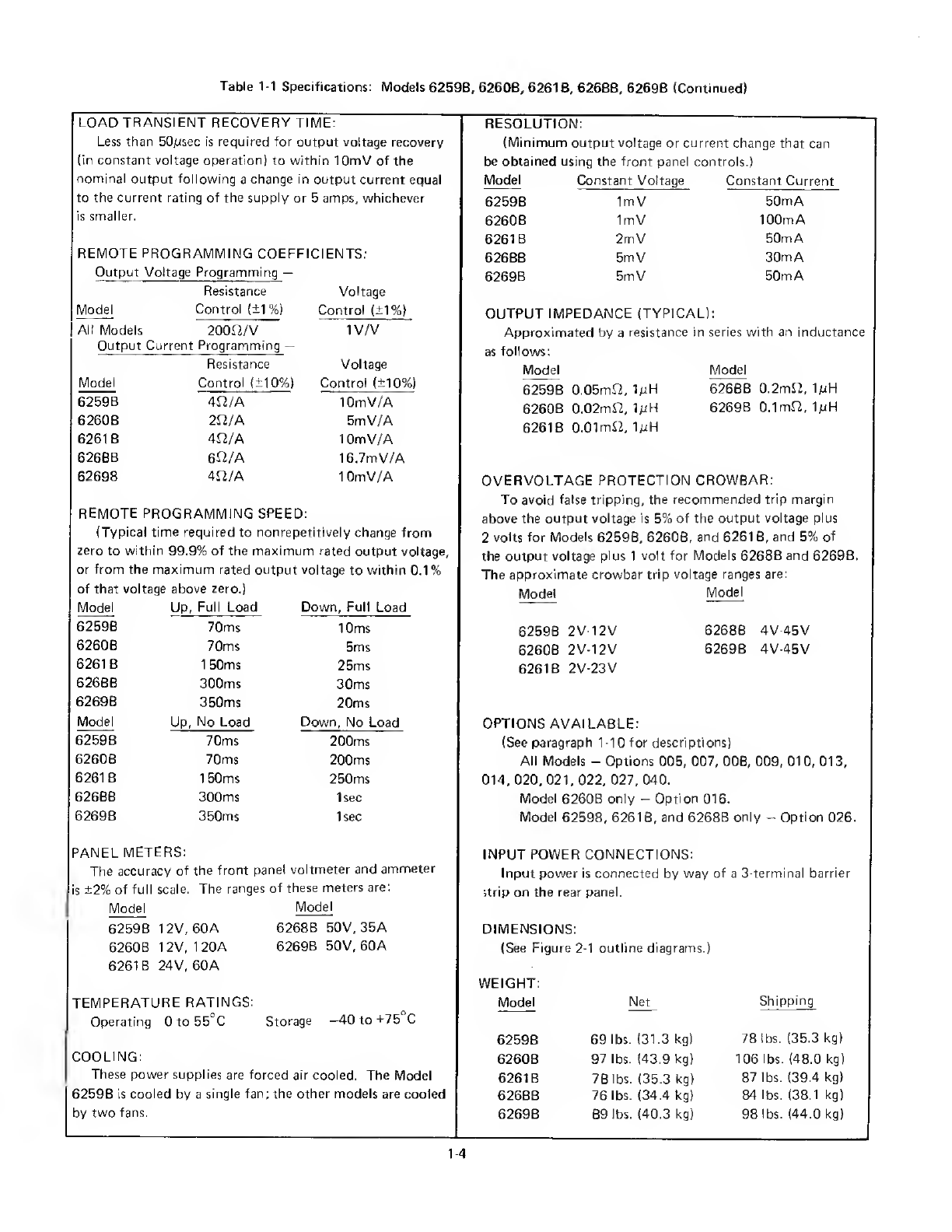
HP 6259B Service manual

REGULATED
DC
POWER
SUPPLY
MODELS
6259B,
6260B,
6261B,
6268B,
6269B
*
OPERATING
AND
SERVICE
MANUAL
FOR
MODEL
6259B,
SERIALS
1535A-00651
AND
ABOVE
MODEL
6260B,
SERIALS
1545A-01026
AND
ABOVE
MODEL
6261B,
SERIALS
1543A-00551
AND
ABOVE
MODEL
6268B,
SERIALS
1539A-01481
AND
ABOVE
MODEL
6269B,
SERIALS
1535A-01631
AND
ABOVE
*
For
instruments
with
serial
numbers
above
those
listed,
a
change
page
may
be
included.
HP
Part
No.
5950-1766
Printed:
March,
1976


TABLE
OF
CONTENTS
Section
Page
I
GENERAL
INFORMATION
_1-1
1-1
DESCRIPTION
.11
1-8
SPECIFICATIONS
.1-1
1-10
OPTIONS
.1-2
1-12
INSTRUMENT/MANUAL
IDENTIFICATION.1-2
1-
15
ORDERING
ADDITIONAL
MANUALS
.1-3
II
INSTALLATION
.
2
1
2-
1
INITIAL
INSPECTION.2-1
2-3
Mechanical
Check
.2-1
2-5
Electrical
Check.:
.
.
2-1
2-7
INSTALLATION
DATA
.2-1
2-9
Location
and
Cooling
.2-1
2-11
Outline
Diagram.2-1
2-13
Rack
Mounting
.2-1
2-15
INPUT
POWER
REQUIREMENTS
.2-1
2-17
INPUT
LINE
VOLTAGE
OR
FREQUENCY
CONVERSION
.
2-2
2-20
Converting
a
Standard
Instrument
to
208-Volt
Operation
(Models
6259B,
6261
B,
and
6268BL
.
.
2-2
2-22
Converting
a
Standard
Instrument
to
208-Volt
Operation
(Models
6260B
and
6269B).2-2
2-24
Converting
a
Standard
Instrument
to
115-Volt
Operation
(Models
6259B,
6261
B,
and
6268B).
.
.
2-2
2-26
Converting
a
Standard
Instrument
to
115-Volt
Operation
(Model
6260B)
.2-3
2-28
Converting
a
Standard
Instrument
to
50Hz
Operation
.2-3
2
30
INPUT
POWER
CONNECTIONS
.
2-3
2-
32
REPACKAGING
FOR
SHIPMENT.24
II!
OPERATING
INSTRUCTIONS
.3-1
3-
1
TURN-ON
CHECKOUT
PROCEDURE.3-1
3-3
OPERATING
MODES.3-2
3
6
NORMAL
OPERATING
MODE.
.
3-2
3-8
Constant
Voltage
Operation
....
3-2
3-10
Constant
Current
Operation
....
3-2
3-12
Overvoltage
Trip
Point
Adjustment.3-2
Section
Page
III
3-15
Connecting
The
Load
.3-3
(con't.)
3-20
Operation
With
No
Load.3-3
3-22
Operation
Beyond
Rated
Output
.3-3
3-24
OPTIONAL
OPERATING
MODES.3-3
3-27
Remote
Voltage
Sensing
.3-3
3-34
Remote
Programming
.3-5
3-51
Auto-Parallel
Operation.3-8
3-57
Auto-Series
Operation.3-8
3-67
Auto-Tracking
Operation.3-10
3-76
SPECIAL
OPERATING
CONSIDERATIONS.3
12
3-77
Pulse
Loading.3-12
3-79
Output
Capacitance.3-12
3-82
Reverse
Voltage
Protection
....
3-12
3-85
Reverse
Current
Loading.3-12
3-87
Battery
Charging.3-12
3-
91
Battery
Discharging.3-13
IV
PRINCIPLES
OF
OPERATION
.
.
4
1
4-
1
OVERALL
BLOCK
DIAGRAM
DISCUSSION_4-1
4-16
DETAILED
CIRCUIT
ANALYSIS.4-3
4-17
Preregulator
Control
Circuit
....
4-3
4-27
Overvoltage
Limit
Circuit.4-4
4-29
Series
Regulator
and
Driver
....
4-4
4-31
Short-Circuit
Protection
.4-4
4-33
Constant-Voltage
Comparator
...
4-4
4-40
Constant-Current
Comparator
...
4-5
4-45
Voltage
Clamp
Circuit.4-6
4-48
Mixer
and
Error
Amplifiers
....
4-6
4-52
Overvoltage
Protection
Crowbar.
.
4-6
4-58
Turn-On
Control
Circuit
.4-7
4-61
Reference
Regulator.4-7
4-66
Meter
Circuit.4-7
4-
70
Additional
Protection
Features
.
.
4-7
V
MAINTENANCE.5-1
5-
1
INTRODUCTION
.5-1
5-3
TEST
EQUIPMENT
REQUIRED.5-2
5-5
PERFORMANCE
TEST.5-2
5-7
CONSTANT-VOLTAGE
TESTS.
.
5-2
5
38
CONSTANT-CURRENT
TESTS.
.
5-6
5-49
TROUBLESHOOTING.5-8
iii

TABLE
OF
CONTENTS
(Continued)
Section
Page
Section
Page
V
5-54
OVERALL
TROUBLE-
V
5-100
Ripple
Balance
Adjustment
.
.
.
5-19
(con't.)
SHOOTING
PROCEDURES
.
5-8
(con't.)
5-102
Preregulator
Tracking
5-60
Disassembly
Procedures
.
.
5-15
Adjustment
.
.
.
5-20
5-69
REPAIR
AND
REPLACEMENT
.
5-16
5-104
Crowbar
Trip
Voltage
5-71
ADJUSTMENT
AND
Adjustment.
.
.
5-20
CALIBRATION
.
.
5-16
5-106
Maximum
Crowbar
Trip
5-73
Meter
Zero
Adjustment.
.
5-16
Voltage
Adjustment.
.
.
5-20
5-75
Voltmeter
Calibration
.
.
5-16
5-108
Disabling
the
Crowbar
.
.
.
.
.
.
5-20
5-77
Ammeter
Calibration
.
.
5-17
5-79
Constant-Voltage
Programming
VI
REPLACEABLE
PARTS
.
.
.
6-1
Calibration.
.
5-17
5-89
Constant-Current
Programming
VII
CIRCUIT
DIAGRAM
AND
Calibration.
.
5-18
COMPONENT
LOCATION
5-98
Load
Transient
Recovery
Time
DIAGRAMS
.
.
.
7-1
Adjustment
.
.
5-19
IV

SECTION
I
GENERAL
INFORMATION
1-1
DESCRIPTION
1
-2
The
five
constant-voltage/constant
current
power
supply
models
included
in
this
manual
use
a
transistor
series-regulator
combined
with
a
triac
preregulator
for
high
efficiency,
excellent
regulation,
and
low
ripple
and
noise.
These
supplies
are
packaged
in
7-inch
high
full-rack-width
cabinets
that
are
suitable
for
either
bench
or
relay
rack
operation.
1
-3
The
outputs
of
these
supplies
can
be
varied
from
zero
to
full
rated
voltage
or
current
by
setting
coarse
and
fine
voltage
and
current
controls
on
the
front
panel
or
they
can
be
programmed
remotely
by
resistance
or
voltage
inputs
to
rear
panel
terminals.
When
the
voltage
controls
are
used
to
establish
a
constant
output
voltage,
the
current
controls
establish
a
current
limit
that
can
protect
the
load
from
over¬
current.
When
the
current
controls
are
used
to
establish
a
constant
output
current,
the
voltage
controls
establish
a
voltage
limit
that
can
protect
the
load
from
excessive
voltage.
The
crossover
from
constant-voltage
to
constant-
current
operation,
or
vice
versa,
occurs
automatically
when
the
load
current
reaches
the
value
established
by
the
current
controls
or
the
voltage
reaches
the
value
established
by
the
voltage
controls.
The
output
voltage
and
current
can
both
be
monitored
continuously
on
front
panel
meters.
1-4
Output
loads
are
further
protected
by
a
built-in
fast-acting
overvoltage
protection
crowbar
circuit
that
automatically
shorts
the
supply's
output
terminals
if
a
preset
voltage
limit
is
exceeded.
A
front
panel
control
sets
the
voltage
at
which
the
crowbar
trips
and
can
be
adjusted
from
approximately
10%
to
110%
of
the
supply's
maximum
rated
voltage.
When
several
supplies
are
installed
in
the
same
system,
whether
in
series,
parallel,
or
independently,
their
crowbar
circuits
can
be
interconnected
so
that
all
will
trip
simultaneously
whenever
any
one
of
them
does.
1
-5
These
power
supplies
are
forced
air
cooled.
1-6
The
ac
input
connections
to
these
supplies
are
made
at
rear
panel
terminals.
All
dc
output,
remote
sensing,
and
remote
programming
connections
are
also
made
at
rear
panel
terminals.
Either
the
positive
or
negative
output
terminal
of
a
supply
may
be
grounded
or
the
supply's
output
may
be
floated
at
up
to
300
volts
above
ground.
1-7
Remote
programming,
remote
sensing,
and
several
methods
of
operating
supplies
in
combination
of
two
or
three
are
made
possible
by
rear
panel
terminals
that
allow
access
to
control
points
within
the
regulator
circuits.
These
capabilities
are
described
below.
a.
Remote
Programming.
The
power
supply's
output
voltage
or
current
(or
both)
can
be
controlled
from
a
remote
location
by
varying
a
resistance
or
a
voltage
input
signal
to
the
supply's
voltage
or
current
regulator
circuit.
b.
Remote
Sensing.
Connecting
the
voltage
regulator's
feedback
circuit
to
the
load
terminals
rather
than
to
the
supply's
output
terminals
prevents
the
voltage
drop
in
the
load
leads
from
impairing
voltage
regulation
at
the
load
when
operating
in
the
constant
voltage
mode.
A
separate
pair
of
sensing
leads
which
carry
no
load
current
extend
the
feedback
loop
to
the
load
terminals.
c.
Auto-Parallel
Operation.
Two
or
three
similar
supplies
connected
in
parallel
can
be
made
to
share
loads
equally
and
can
be
controlled
by
the
voltage
and
current
controls
(or
remote
programming
terminals)
of
one
of
the
supplies
designated
the
master
if
they
are
connected
for
auto-parallel
operation.
Normally,
only
supplies
having
the
same
model
number
are
connected
in
auto-parallel,
but
auto-parallel
operation
can
be
used
with
any
of
the
supplies
covered
by
this
manual
that
have
equal
current
capabilities.
d.
Auto-Series
Operation.
Two
or
three
supplies
can
be
connected
in
series
and
have
their
outputs
simultaneously
controlled
by
the
voltage
and
current
controls
(or
remote
programming
terminals)
of
one
of
the
supplies
designated
the
master.
The
voltage
contributed
by
each
slave
is
main¬
tained
in
a
constant
ratio
to
that
of
the
master.
These
ratios
can
be
set
as
desired.
Auto-series
operation
provides
higher
output
voltages
in
constant
voltage
operation
and
greater
voltage
compliance
in
constant
current
operation.
Any
HP
supply
that
offers
auto-series
operation
can
serve
as
a
slave
supply;
the
master
supply
does
not
have
to
be
an
auto-series
model.
e.
Auto-Tracking
Operation.
Auto-tracking
is
similar
to
auto-series
operation
except
that
two
or
three
supplies
share
a
common
negative
output
bus
and
are
interconnected
so
that
the
output
voltage
of
each
slave
supply
is
maintained
at
some
constant
fraction
of
that
of
the
master
supply.
All
of
the
supplies
are
controlled
through
the
master
supply,
and
each
supply
feeds
a
separate
load.
1-8
SPECIFICATIONS
1-9
Detailed
specifications
for
these
power
supplies
are
given
in
Table
1
-1.
M

1-10
OPTIONS
Option
No.
Description
1-11
Options
are
customer-requested
factory
modifica¬
tions
of
a
standard
instrument.
The
following
options
are
available
for
the
instruments
covered
by
this
manual.
Where
necessary,
detailed
coverage
of
the
options
is
included
throughout
the
manual.
Option
No.
Description
005
Realign
ment
for
50Hz
Operation
:
Standard
instruments
are
designed
for
57
to
63Hz
operation.
For
50Hz
operation,
a
resistor
in
the
preregulator
control
circuit
is
changed
and
the
preregulator
is
realigned.
007
T
en-Turn
Output
Voltage
Control:
A
ten-
turn
control
replaces
the
coarse
voltage
con¬
trol
for
improved
resolution
in
setting
the
output
voltage.
008
Ten-Turn
Output
Current
Control:
A
ten-
turn
control
replaces
the
coarse
current
control
for
improved
resolution
in
setting
the
output
current.
009
Ten-Turn
Output
Voltage
and
Current
Control
s:
This
option
includes
Options
007
and
008
in
the
same
instrument.
010
C
hassis
Slides
:
Factory
installed
slides
permit
convenient
access
to
the
interior
of
a
rack
mounted
supply
for
maintenance.
013
Three-Digit
Graduated
Decadial
Voltage
Control:
To
improve
mechanical
stability
and
permit
accurate
resetting
of
the
output
voltage,
Option
013
replaces
the
coarse
voltage
control
with
a
ten-turn
control
equipped
with
a
3-digit
turns-counting
dial.
014
Three-Digit
Graduated
Decadial
Current
Control
:
To
improve
mechanical
stability
and
permit
accurate
resetting
of
the
output
current.
Option
014
replaces
the
coarse
current
control
with
a
ten-turn
control
equipped
with
a
3-digit
turns-counting
dial.
016
Rewiring
for
11
5Vac
±10%
Single-Phase
Input
(Model
6260B
only):
This
factory
modification
replaces
the
circuit
breaker
and
power
transformer,
adds
a
resistor
to
the
A2
assembly,
and
reconnects
the
bias
trans¬
former,
preregulator
choke,
and
fans
for
11
5Vac
operation.
020
Adjustable
Voltage
Programming
:
Two
screwdriver-adjustable
controls
accessible
through
holes
in
the
rear
panel
allow
the
voltage
programming
coefficient
and
zero
output
voltage
to
be
adjusted
conveniently
to
an
accuracy
of
0.1%.
021
Adjustable
Current
Programming:
Two
screwdriver-adjustable
controls
accessible
through
holes
in
the
rear
panel
allow
the
current
programming
coefficient
and
zero
output
current
to
be
adjusted
conveniently
to
an
accuracy
of
0.1%.
022
Adjustable
Voltage
and
Current
Programming:
This
option
includes
Options
020
and
021
in
the
same
instrument.
026
Rewiring
for
11
5Vac
±10%
Single-Phase
Input
(Models
6259B,
6261
B,
and
6268B
only):
This
factory
modification
replaces
the
circuit
breaker
(except
in
the
Model
6259B),
adds
a
resistor
to
the
A2
assembly,
and
reconnects
the
power
transformer,
bias
transformer,
preregulator
choke,
and
fans
for
115Vac
operation.
027
Rewiring
for
208Vac
+10%
Single-Phase
Input:
This
factory
modification
reconnects
the
power
and
bias
transformers
for
208Vac
operation.
040
Interfacing
for
Mu
ltiprogrammer
Operation
:
This
factory
modification
prepares
standard
power
supplies
for
resistance
programming
by
the
6940B
Multiprogrammer
or
the
6941
B
Multiprogrammer
Extender.
Operation
with
either
of
these
instruments
requires
that
the
power
supply
be
subjected
to
a
special
calibration
and
a
protection
checkout.
The
special
calibration
insures
that
the
power
supply
can
be
accurately
set
to
zero
and
to
the
maximum
rated
output
voltage
or
current
when
programmed
by
the
multiprogrammer.
The
protection
checkout
insures
that
the
power
supply
will
not
be
damaged
by
the
rapid
repetitive
programming
possible
with
the
multiprogrammer.
This
option
includes
Option
022.
1-12
INSTRUMENT/MANUAL
IDENTIFICATION
1-13
Hewlett-Packard
power
supplies
are
identified
by
a
1-2

two-part
serial
number.
The
first
part
is
the
serial
number
prefix,
a
number-letter
combination
that
denotes
the
date
of
a
significant
design
change
and
the
country
of
manu¬
facture.
The
first
two
digits
indicate
the
year
(10
=
1970,
11
=
1971,
etc.),
the
second
two
digits
indicate
the
week,
and
the
letter
"A”
designates
the
U.
S.
A.
as
the
country
of
manufacture.
The
second
part
is
the
power
supply
serial
number.
A
different
sequential
number
is
assigned
to
each
power
supply,
starting
with
001
01.
1-14
If
the
serial
number
on
your
instrument
does
not
agree
with
those
on
the
title
page
of
the
manual.
Change
Sheets
supplied
with
the
manual
define
the
differences
between
your
instrument
and
the
instrument
described
by
this
manual.
1-15
ORDERING
ADDITIONAL
MANUALS
1-16
One
manual
is
shipped
with
each
power
supply.
Additional
manuals
may
be
purchased
from
your
local
Hewlett-Packard
field
office
(see
list
at
rear
of
this
manual
for
addresses).
Specify
the
model
number,
serial
number
prefix,
and
HP
part
number
shown
on
the
title
page.
Table
1-1
Specifications:
Models
6259B,
6260B,
6261B,
6268B,
6269B
INPUT:
230Vac
±10%,
single
phase,
57-63Hz
for
the
standard
models.
(For
other
input
voltages
or
50Hz
operation,
see
the
option
listings
in
paragraph
1-10.
Input
power
require¬
ments
are
listed
in
paragraph
2-1
5.
OUTPUT:
Model
6259B
0-10
volts
at
0-50
amps
6260B
0-10
volts
at
0-100
amps
6261
B
0-20
volts
at
0-50
amps
6268B
0-40
volts
at
0-30
amps
6269B
0-40
volts
at
0-50
amps
LOAD
EFFECT
(LOAD
REGULATION):
Constant
Voltage
—
Less
than
0.01%
of
output
plus
200pV
for
a
load
change
equal
to
the
current
rating
of
the
supply.
Constant
Current
—
Models
6259B
and
6261
B
-
Less
than
0.02%
of
output
plus
1
mA
for
a
load
change
equal
to
the
voltage
rating
of
the
supply.
Models
6260B,
6268B,
and
6269B
-
Less
than
0.02%
of
output
plus
2mA
for
a
load
change
equal
to
the
voltage
rating
of
the
supply.
SOURCE
EFFECT
(LINE
REGULATION):
Constant
Voltage
-
Less
than
0.01
%
of
output
plus
200pV
for
a
change
in
line
voltage
between
208
and
254Vac
(or
104
and
1
27Vac)
at
any
output
voltage
and
current
within
rating.
Constant
Current
-
Models
6259B
and
6261
B
-
Less
than
0.02%
of
output
plus
1
mA
for
a
change
in
line
voltage
between
208
and
254Vac
(or
104
and
127Vac)
at
any
output
voltage
and
current
within
rating.
Models
6260B,
6268B,
and
6269B
-
Less
than
0.02%
of
output
plus
2mA
for
a
change
in
line
voltage
between
208
and
254Vac
(or
104
and
127
Vac)
at
any
output
voltage
and
current
within
rating.
PARD
(RIPPLE
AND
NOISE):
(Measured
within
20Hz
to
20MHz
bandwidth)
Model
Constant
Voltage
Constant
Current
6259B
500pVrms/5mV
p-p
25mA
rms
6260B
500pVrms/5mV
p-p
50mA
rms
6261
B
500pVrms/5mV
p-p
25mA
rms
6268B
1
mVrms/5mV
p-p
20mA
rms
6269B
1mVrms/5mV
p-p
25mA
rms
TEMPERATURE
COEFFICIENT:
Constant
Voltage
-
Less
than
0.01%
plus
200pV
change
in
output
per
degree
Celsius
change
in
ambient
following
a
30-minute
warmup.
Constant
Current
-
Models
6259B,
6261
B,
and
6269B
-
Less
than
0.01
%
plus
4mA
change
in
output
per
degree
Celsius
change
in
ambient
following
a
30-minute
warmup.
Model
6260B
-
Less
than
0.01
%
plus
8mA
change
in
output
per
degree
Celsius
change
in
ambient
following
a
30-minute
warmup.
Model
6268B
-
Less
than
0.01%
plus
2mA
change
in
output
per
degree
Celsius
change
in
ambient
following
a
30-minute
warmup.
DRIFT
(STABILITY):
(Change
in
output
(dc
to
20Hz)
over
an
8-hour
interval
under
constant
line,
load,
and
ambient
temperature
follow¬
ing
a
30-minute
warmup.)
Constant
Voltage
-
Less
than
0.03%
of
output
plus
2mV.
Constant
Current
—
Models
6259B,
6261
B,
and
6269B
-
Less
than
0.03%
of
output
plus
10mA.
Model
6260B
-
Less
than
0.03%
of
output
plus
20mA.
Model
6268B
-
Less
than
0.03%
of
output
plus
5mA.
1-3

Table
1-1
Specifications:
Models
6259B,
6260B,
6261B,
6268B,
6269B
(Continued)
LOAD
TRANSIENT
RECOVERY
TIME:
Less
than
50/Jsec
is
required
for
output
voltage
recovery
(in
constant
voltage
operation)
to
within
lOmV
of
the
nominal
output
following
a
change
in
output
current
equal
to
the
current
rating
of
the
supply
or
5
amps,
whichever
is
smaller.
REMOTE
PROGRAMMING
COEFFICIENTS:
Output
Voltage
Programming
—
Resistance
Voltage
Model
Control
(±1
%)
Control
(±1%)
All
Models
200JT2/V
1V/V
Output
Current
Programming
—
Resistance
Voltage
Model
Control
(±10%)
Control
(±10%)
6259B
4I2/A
lOmV/A
6260B
2£2/A
5mV/A
6261
B
4L2/A
10m
V/A
6268B
6J2/A
16.7mV/A
6269
B
4L2/A
1
OrnV/A
REMOTE
PROGRAMMING
SPEED:
(Typical
time
required
to
nonrepetitively
change
from
zero
to
within
99.9%
of
the
maximum
rated
output
voltage
or
from
the
maximum
rated
output
of
that
voltage
above
zero.)
voltage
to
within
0.1
%
Model
Up,
Full
Load
Down,
Full
Load
6259B
70ms
10ms
6260B
70ms
5ms
6261
B
1
50ms
25ms
6268B
300ms
30ms
6269B
350ms
20ms
Model
Up,
No
Load
Down,
No
Load
6259B
70ms
200ms
6260B
70ms
200ms
6261
B
1
50ms
250ms
6268B
300ms
Isec
6269B
350ms
Isec
PANEL
METERS:
The
accuracy
of
the
front
panel
voltmeter
and
ammeter
is
±2%
of
full
scale.
The
ranges
of
these
meters
are:
Model
Model
6259B
12V,60A
6268B
50V,35A
6260B
12V,
120A
6269B
50V,
60A
6261
B
24V,
60A
TEMPERATURE
RATINGS:
Operating
0
to
55'C
Storage
-40
to
+75
C
COOLING:
These
power
supplies
are
forced
air
cooled.
The
Model
6259B
is
cooled
by
a
single
fan;
the
other
models
are
cooled
by
two
fans.
RESOLUTION:
(Minimum
output
voltage
or
current
change
that
can
be
obtained
using
the
front
panel
controls.)
Model
Constant
Voltage
Constant
Current
6259
B
1
m
V
50mA
6260B
1
mV
100mA
6261B
2mV
50mA
6268B
5m
V
30mA
6269B
5m
V
50mA
OUTPUT
IMPEDANCE
(TYPICAL):
Approximated
by
a
resistance
in
series
with
an
inductance
as
follows:
Model
Model
6259B
0.05mft,
IpH
6268B
0.2m£2,
1/uH
6260B
0.02m£2,
IpH
6269B
0.1m£2,
IpH
6261
B
0.01mS2,
IpH
OVERVOLTAGE
PROTECTION
CROWBAR:
To
avoid
false
tripping,
the
recommended
trip
margin
above
the
output
voltage
is
5%
of
the
output
voltage
plus
2
volts
for
Models
6259B,
6260B,
and
6261
B,
and
5%
of
the
output
voltage
plus
1
volt
for
Models
6268B
and
6269B.
The
approximate
crowbar
trip
voltage
ranges
are:
Model
Model
6259B
2V-12V
6268B
4V-45V
6260B
2V-12V
6269B
4V-45V
6261
B
2V-23V
OPTIONS
AVAILABLE:
(See
paragraph
1-10
for
descriptions)
All
Models
-
Options
005,
007,
008,
009,
010,
013,
014,
020,
021,
022,
027,
040.
Model
6260B
only
—
Option
016.
Model
6259B,
6261
B,
and
6268B
only
—
Option
026.
INPUT
POWER
CONNECTIONS:
Input
power
is
connected
by
way
of
a
3-terminal
barrier
Trip
on
the
rear
panel.
DIMENSIONS:
(See
Figure
2-1
outline
diagrams.)
WEIGHT:
Model
Net
Shipping
6259B
69
lbs.
(31.3
kg)
78
lbs.
(35.3
kg)
6260B
97
lbs.
(43.9
kg)
106
lbs.
(48.0
kg)
6261
B
78
lbs.
(35.3
kg)
87
lbs.
(39.4
kg)
6268B
76
lbs.
(34.4
kg)
84
lbs.
(38.1
kg)
6269B
89
lbs.
(40.3
kg)
98
lbs.
(44.0
kg)
1-4

SECTION
II
INSTALLATION
2-1
INITIAL
INSPECTION
2-2
Before
shipment,
this
instrument
was
inspected
and
found
to
be
free
of
mechanical
and
electrical
defects.
As
soon
as
the
instrument
is
unpacked,
inspect
for
any
damage
that
may
have
occurred
in
transit.
Save
all
packing
materials
until
the
inspection
is
completed.
If
damage
is
found,
file
a
claim
with
the
carrier
immediately.
The
Hewlett-Packard
Sales
and
Service
office
should
be
notified
as
soon
as
possible.
2-3
Mechanical
Check
2-4
This
check
should
confirm
that
there
are
no
broken
knobs
or
connectors,
that
the
cabinet
and
panel
surfaces
are
free
of
dents
and
scratches,
and
that
the
meters
are
not
scratched
or
cracked.
2-5
Electrical
Check
2-6
The
instrument
should
be
checked
against
its
electrical
specifications.
Section
V
includes
an
"in-cabinet”
performance
check
to
verify
proper
instrument
operation.
2-7
INSTALLATION
DATA
2-8
The
instrument
is
shipped
ready
for
permanent
rack
installation
or
bench
operation.
It
is
necessary
only
to
connect
the
instrument
to
a
source
of
power
and
it
is
ready
for
use.
2-9
Location
and
Cooling
2-10
These
instruments
are
fan-cooled
and
must
be
installed
with
sufficient
space
for
cooling
air
to
reach
their
sides.
These
power
supplies
should
be
used
in
an
area
where
the
ambient
temperature
does
not
exceed
55"C.
2-11
Outline
Diagram
2-1
2
Figure
2-1
shows
the
outline
shape
and
dimensions
of
these
supplies.
2-13
Rack
Mounting
2-14
This
instrument
is
full
rack
size
and
can
be
easily
rack
mounted
in
a
conventional
19-inch
rack
panel
using
standard
mounting
screws.
TERMINAL
STRIP
DETAIL
-esi;te
.*•:«»«
5.1
n
sing
336=?
tEPM
0
52
-!/«•
70
ffrON'
Cl¥ENOCHS
6
9e8:ir?*<p'
■*
9C0C"4$2
6nr.'
*1*
5
50'.4
8»t
i
TOP
3'S
•
54
9mr»|
JJSCC
--•».
SIDE
Figure
2-1.
Outline
Diagrams
(Models
6259B,
6260B,
6261B,
6268B,
and
6269B)
2-15
INPUT
POWER
REQUIREMENTS
2-16
The
standard
instrument
is
wired
for
a
nominal
input
of
230Vac
57-63Hz
when
it
is
shipped
from
the
factory.
The
supplies
covered
by
this
manual
are
also
available
equipped
for
a
208-volt
input
(Option
027),
and
except
for
the
Model
6269B,
are
also
available
equipped
for
a
115-volt
input
(Option
026
for
Models
6259B,
6261
B,
and
6268B,
or
Option
016
for
the
Model
6260B).
In
addition,
all
five
models
are
available
in
a
50Hz
version.
The
input
voltage
and
frequency
required
is
marked
on
the
rear
panel
of
the
supply.
Except
for
the
Model
6269B,
which
cannot
be
converted
to
11
5-volt
operation,
a
standard
instrument
can
be
converted
by
the
user
to
208
or
11
5-volt
and
to
50Hz
operation
by
following
the
instructions
given
in
the
follow¬
ing
paragraphs.
The
standard
instrument
requires
the
input
current
and
power
listed
below
when
operated
at
full
load
from
a
230-volt
source.
When
the
supply
is
operated
from
a
115-volt
source,
the
input
current
is
approximately
twice
the
amount
listed.
Model
Input
Current
Input
Powe
6259B
6A
850W
6260B
12A
1600W
6261B
12A
1500W
6268B
12A
1600W
6269B
18A
2500W

2-17
INPUT
LINE
VOLTAGE
OR
FREQUENCY
CONVERSION
2-1
8
Converting
a
230-volt
instrument
to
208-volt
operation
is
simply
a
matter
of
changing
some
taps
or
jumper
connections
on
main
power
transformer
T1
and
bias
transformer
A3T2.
Converting
to
11
5-volt
operation
is
more
involved.
The
Models
6259B,
6260B,
6261
B,
and
6268B
require
an
added
resistor
and
some
jumper
changes
in
the
A2
RFI
assembly
and
a
changed
A3T2
transformer
tap.
In
addition,
the
6260B,
6261
B,
and
6268B
need
a
replacement
circuit
breaker,
and
the
6260B
needs
a
replace¬
ment
T1
power
transformer.
Complete
line
voltage
con¬
version
instructions
are
given
in
paragraphs
2-20
through
2-27.
2-19
Converting
a
60Hz
instrument
to
50Hz
operation
requires
that
one
resistor
be
replaced
and
some
adjustments
be
made.
Line
frequency
conversion
instructions
are
given
in
paragraph
2-28.
2-20
Converting
a
Standard
Instrument
to
208-
Volt
Operation
(Models
6259B,
6261B
and
6268B).
2-21
To
convert
these
230-volt
instruments
to
208-volt
operation,
proceed
as
follows:
a.
Disconnect
instrument
from
power
source
and
remove
top
and
bottom
covers.
b.
Remove
A2
RFI
assembly
as
described
in
steps
(a)
through
(c)
of
paragraph
5-65.
This
provides
access
to
bias
transformer
A3T2
(see
Fig.
7-2).
c.
Locate
the
wire
that
connects
circuit
breaker
CB1
to
the
A3T2
bias
transformer
terminal
marked
"230V”,
disconnect
it
from
the
transformer,
and
reconnect
it
to
the
terminal
marked
"208V".
Leave
the
wire
from
fan
B2
(not
used
in
the
6259B)
connected
to
the
terminal
marked
"230V"
(see
Fig.
2-2B).
d.
Re-install
the
RFI
assembly
by
reversing
the
proce¬
dure
of
step
(b)
above.
e.
Unsolder
the
wire
connected
to
terminal
5
of
power
transformer
T1
and
solder
it
instead
to
terminal
4
(see
Figure
2-3B).
2-22
Converting
a
Standard
Instrument
to
208-
Volt
Operation
(Models
6260B
and
6269B).
2-23
To
convert
these
230-volt
instruments
to
208-
volt
operation,
proceed
as
follows:
a.
Perform
steps
(a)
through
(d)
of
paragraph
2-21.
b.
Unsolder
the
wire
connected
to
the
terminal
marked
"230V"
on
power
transformer
T1
and
solder
it
instead
to
the
terminal
marked
"208V"
(see
Fig.
2-4B).
2-24
Converting
a
Standard
Instrument
to
115-
Volt
Operation
(Models
6259B,
6261B
and
6268B).
A
BIAS
TRANSFORMER
(A3T2)
CONNECTIONS
FOR
230
VOLT
OPERATION.
B
BIAS
TRANSFORMER
(A3T2)
CONNECTIONS
FOR
208
VOLT
OPERATION.
C
BIAS
TRANSFORMER
(A3T2)
CONNECTIONS
FOR
115
VOLT
OPERATION.
NOTE-
X
FAN
B2
IS
NOT
USED
IN
MODEL
62596
Figure
2-2.
Bias
Transformer
Primary
Connections
for
208Vac
Operation
(Modal
6259B,
6260B,
6261B,
6268B,
and
6269B)
and
115Vac
Operation
(except
Model
6269B).
2-2

2-25
To
convert
these
230-volt
instruments
to
11
5-volt
operation,
proceed
as
follows:
a.
(Omit
this
step
for
the
Model
6259B.)
Obtain
and
install
a
new
circuit
breaker
CB1.
Refer
to
Option
026
in
the
Table
6-4
parts
list
for
its
current
rating
and
HP
Part
Number.
Connections
to
the
replacement
are
the
same
as
those
to
the
original
breaker.
b.
Remove
and
partially
disassemble
the
A2
RFI
assembly
as
described
in
steps
(a)
through
(d)
of
paragraph
5-65.
c.
Unsolder
jumper
J3
from
the
A2
circuit
board
(see
Fig.
7-1)
and
install
jumpers
J1
and
J2.
Also
install
resistor
A2R3
on
the
circuit
board.
Refer
to
Option
026
in
the
Table
6-4
parts
list
for
its
description
and
HP
Part
Number.
Replace
cover
on
RFI
assembly.
d.
Locate
the
wire
that
connects
circuit
breaker
CB1
to
the
A3T2
bias
transformer
terminal
marked
"230V”,
disconnect
it
from
the
transformer,
and
reconnect
it
to
the
terminal
marked
"115V."
Also
disconnect
the
wire
from
fan
B2
(not
used
in
the
6259B)
from
the
terminal
marked
"230V"
and
reconnect
it
to
the
terminal
marked
"0V”
(see
Fig.
2-2C).
e.
Re-install
the
RFI
assembly
by
reversing
the
procedure
of
step
(b).
f.
Unsolder
the
jumper
connecting
terminals
2
and
3
of
power
transformer
T1
(see
Fig.
2-3C)
and
solder
jumpers
between
terminals
1
and
3,
and
2
and
5.
2-26
Converting
a
Standard
Instrument
to
115-
Volt
Operation
(Model
6260B)
2-27
To
convert
the
standard
Model
6260B
to
11
5-volt
operation,
proceed
as
follows:
a.
Obtain
and
install
a
new
power
transformer
(T1)
and
a
new
circuit
breaker
(CB1).
Refer
to
Option
016
in
the
Table
6-4
parts
list
for
their
description
and
HP
Part
Number.
The
new
transformer
has
two
primary
terminals.
Transfer
the
wire
from
the
”0V"
terminal
on
the
old
trans¬
former
to
the
"0V"
on
the
new
one,
and
from
the
”230V”
terminal
on
the
old
one
to
the
"115V''
terminal
on
the
new
one.
The
connections
to
the
replacement
circuit
breaker
are
the
same
as
to
the
old
one.
b.
Perform
steps
(b)
through
(e)
of
paragraph
2-25.
2-28
Converting
a
Standard
Instrument
to
50Hz
Operation
2-29
To
convert
a
60Hz
instrument
to
50Hz
operation,
proceed
as
follows:
a.
Replace
A1
R82
with
a
240
ohm
5%
1/2-watt
resistor.
Refer
to
the
Table
6-4
parts
list
under
Option
005
for
the
HP
Part
Number
of
a
suitable
replacement.
b.
After
replacing
A1
R82,
perform
the
preregulator
tracking
adjustment
given
in
paragraph
5-102.
c.
Check
the
ripple
balance
adjustment
by
the
procedure
given
in
paragraph
5-100.
2-31
No
input
power
cable
is
supplied
with
the
instru¬
ments
covered
by
this
manual.
Input
power
connections
are
made
to
a
3-terminal
barrier
block
on
the
rear
panel.
Its
center
terminal
is
grounded
to
the
instrument
chassis.
To
protect
operating
personnel,
the
National
Electrical
Manufacturers
Association
(NEMA)
recommends
that
the
instrument
panel
and
cabinet
be
grounded.
The
user-
supplied
power
cable
should
have
three
conductors
(with
the
third
conductor
grounded)
and
should
be
of
adequate
wire
size
to
handle
the
input
current
drawn
by
the
supply
(see
paragraph
2-15).
Note
that
when
the
supply
is
opera¬
ted
from
a
11
5-volt
source,
the
input
current
is
approxi¬
mately
twice
that
shown
in
paragraph
2-1
5.
2-3

2-32
REPACKAGING
FOR
SHIPMENT
2*33
To
insure
safe
shipment
of
the
instrument,
it
is
recommended
that
the
package
designed
for
the
instrument
be
used.
The
original
packaging
material
is
reusable.
If
it
is
not
available,
contact
your
local
Hewlett-Packard
field
office
to
obtain
the
materials.
This
office
will
also
furnish
the
address
of
the
nearest
service
office
to
which
the
instrument
can
be
shipped
and
provide
the
Authorized
Return
label
necessary
to
expedite
the
handling
of
your
instrument
return.
Be
sure
to
attach
a
tag
to
the
instrument
which
specifies
the
owner,
model
number,
full
serial
number,
and
service
required,
or
a
brief
description
of
the
trouble.
ov
A
INPUT
POWER
TRANSFORMER
[TO
CONNECTIONS
FOR
230
VOLT
OPERATION.
OV
B
INPUT
POWER
TRANSFORMER
(Tl)
CONNECTIONS
FOR
208
VOLT
OPERATION.
Figure
2-4.
Power
Transformer
Tl
Primary
Connections
for
208Vac
Operation
(Model
6260B
and
6269B)
2-4

SECTION
III
OPERATING
INSTRUCTIONS
Figure
3-1.
Front
Panel
Controls
and
Indicators
3-1
TURN-ON
CHECKOUT
PROCEDURE
3-2
The
following
steps
describe
the
use
of
the
front
panel
controls
and
indicators
illustrated
in
Figure
3-1
and
serve
as
a
brief
check
that
the
supply
is
operational.
This
checkout
procedure
or
the
more
detailed
performance
test
of
paragraph
5-5
should
be
followed
when
the
instru¬
ment
is
received
and
before
it
is
connected
to
any
load
equipment.
Proceed
to
the
more
detailed
test
and
trouble¬
shooting
procedures
in
Section
V
if
any
difficulties
are
encountered.
a.
Turn
CURRENTcontrols
(7)
and
OVERVOLTAGE
ADJUST
potentiometer
(5)
fully
clockwise
and
check
that
rear
panel
straps
are
connected
as
shown
in
Figure
3-2,
but
do
not
connect
load
R^.
b.
Connect
ac
power
of
the
appropriate
voltage
and
frequency
to
the
rear
panel
ac
and
acc
terminals.
The
supply's
input
rating
is
identified
on
its
rear
panel.
-CAUTION-
Do
not
interchange
the
ac
and
acc
input
lines;
connect
the
ac
input
terminal
to
the
hot
side
and
the
acc
input
terminal
to
the
grounded
side
of
the
ac
line.
Do
not
fail
to
connect
the
input
ground
terminal
<
±
)
securely
to
an
external
earth
ground.
c.
Set
LINE
switch
or
circuit
breaker
(7)
ON
and
observe
that
pilot
lamp
(2)
lights.
d.
Adjust
COARSE
and
FINE
VOLTAGE
controls
@
for
desired
indication
on
voltmeter
©
e.
Ensure
that
overvoltage
crowbar
circuit
is
operational
by
slowly
turning
OVERVOLTAGE
ADJUST
control
©
counterclockwise
with
a
screwdriver
until
OVERVOLTAGE
lamp
©
lights
and
voltmeter
indication
drops
to
zero
volts.
3-1

f.
Reset
crowbar
by
returning
OVERVOLTAGE
ADJUST
control
to
its
maximum
clockwise
position
and
turning
off
the
supply.
On
turning
the
supply
back
on,
the
voltage
should
be
the
same
value
as
was
set
in
step
(d).
g.
To
check
the
constant
current
circuit,
first
turn
off
the
supply,
connect
a
short
across
the
output
bus
bars
(see
Figure
3-2),
and
turn
it
back
on.
h.
Adjust
COARSE
and
FINE
CURRENT
controls
(7)
until
ammeter
(8)
indicates
desired
output
current
or
current
limit.
(The
VOLTAGE
controls
must
be
set
for
a
greater-than-zero
output
to
obtain
the
output
current
programmed.)
i.
Turn
off
the
supply,
remove
the
short
from
its
out¬
put,
and
read
the
remainder
of
these
operating
instructions
before
connecting
the
supply
to
an
actual
load.
3-3
OPERATING
MODES
3-4
This
power
supply
is
designed
so
that
its
mode
of
operation
can
be
selected
by
making
strapping
connections
between
terminals
on
its
rear
panel.
The
following
para¬
graphs
first
describe
normal
operation
using
the
normal
strapping
pattern
as
it
is
connected
at
the
factory.
Later
paragraphs
cover
some
optional
operating
modes
including
remote
voltage
sensing,
remote
programming,
and
some
methods
of
operating
these
power
supplies
in
combinations
of
two
or
three.
3-5
The
DC
Power
Supply
Handbook,
Application
Note
90A,
is
a
useful
source
of
additional
information
on
using
regulated
power
supplies
effectively.
This
138-page
handbook
includes
chapters
on
operating
principles,
ac
and
load
connections,
optional
operating
modes,
and
performance
measurements
and
is
available
at
no
charge
from
your
local
HP
sales
office.
The
address
of
your
local
sales
office
can
be
found
in
the
back
of
this
manual.
3-6
NORMAL
OPERATING
MODE
3-7
This
power
supply
was
shipped
with
the
proper
rear
panel
strapping
connections
made
for
constant-voltage/
constant-current
operation
with
local
sensing
and
local
programming.
This
strapping
pattern
is
illustrated
in
Figure
3-2.
By
means
of
the
front
panel
voltage
and
current
controls,
the
operator
selects
either
a
constant-voltage
or
a
constant-current
output.
Whether
the
supply
functions
in
the
constant-voltage
or
the
constant-current
mode
depends
on
the
settings
of
the
voltage
and
current
controls
and
on
the
resistance
of
the
output
load.
For
values
of
load
resis¬
tance
greater
than
a
critical
crossover
value
equal
to
the
voltage
setting
divided
by
the
current
setting,
the
supply
operates
in
the
constant-voltage
mode.
With
a
load
resis¬
tance
smaller
than
this
critical
value,
it
operates
in
the
constant-current
mode.
The
transition
occurs
automati¬
cally;
no
switches
need
to
be
operated
or
connections
changed.
EXT.
CROWBAR
TRIGGER
'
+
-
'
AI
A2
A3
A4
A5
A6
A7
A8
fS
-S
A9
i
IE
3E
p
0
r
t-i
5
-OUT
-0
+
OUT
Figure
3-2.
Normal
Strapping
Pattern
3-8
Constant
Voltage
Operation
3-9
To
adjust
the
supply
for
constant
voltage
operation:
a.
Turn
on
supply
and,
with
output
terminals
open,
adjust
the
VOLTAGE
controls
for
the
desired
output
voltage.
Then
turn
power
off.
b.
Connect
a
short
across
the
rear
panel
output
terminals,
restore
power,
and
adjust
the
CURRENT
controls
for
the
desired
maximum
output
current.
Then
remove
the
short.
If
a
load
change
causes
this
current
limit
to
be
exceeded,
the
supply
automatically
crosses
over
to
constant
current
operation
at
this
preset
current
limit
and
the
output
voltage
drops
proportionately.
In
setting
the
current
limit,
make
an
adequate
allowance
for
high
peak
currents
that
could
cause
unwanted
crossover.
(Refer
to
paragraph
3-77.)
3-10
Constant
Current
Operation
3-11
To
adjust
the
supply
for
constant
current
operation;
a.
Connect
a
short
across
the
rear
output
terminals,
turn
the
power
on,
and
adjust
the
CURRENT
controls
for
the
desired
output
current.
b.
Open
the
output
terminals
and
adjust
the
VOLTAGE
controls
for
the
desired
maximum
output
voltage.
If
a
load
change
causes
this
voltage
limit
to
be
exceeded,
the
supply
automatically
crosses
over
to
constant
voltage
opera¬
tion
at
this
preset
voltage
limit
and
the
output
current
drops
proportionately.
In
setting
the
voltage
limit,
make
an
adequate
allowance
for
high
peak
voltages
that
could
cause
unwanted
crossover.
(Refer
to
paragraph
3-77.)
3-12
Overvoltage
Trip
Point
Adjustment
3-13
The
crowbar
trip
voltage
is
adjusted
by
using
the
screwdriver
control
on
the
front
panel.
The
approximate
trip
voltage
ranges
are
listed
in
Table
1
-1.
When
the
crowbar
trips,
an
SCR
shorts
the
output
and
the
amber
OVER¬
VOLTAGE
indicator
on
the
front
panel
lights.
Rotating
the
control
clockwise
sets
the
trip
voltage
higher.
(It
is
set
to
maximum
at
the
factory.)
Paragraph
5
108
contains
instruc¬
tions
for
completely
disabling
the
crowbar,
if
this
is
desired.

3-14
When
adjusting
the
crowbar
trip
point,
the
possibility
of
false
tripping
must
be
considered.
If
the
trip
voltage
is
set
too
close
to
the
supply's
operating
voltage,
a
transient
in
the
output
would
falsely
trip
the
crowbar.
For
this
reason
it
is
recommended
that
the
crowbar
be
set
higher
than
the
output
voltage
by
5%
of
the
output
voltage
plus
2
volts
for
the
Models
6259B,
6260B,
or
6261
B,
or
5%
of
the
output
voltage
plus
one
volt
for
the
Models
6268B
or
6269B.
If
an
occasional
tripping
of
the
crowbar
can
be
tolerated
as
a
load
is
being
disconnected,
the
crowbar
trip
point
can
be
set
much
closer
to
the
operating
voltage
of
the
supply.
3-15
Connecting
The
Load
3-16
To
satisfy
the
requirements
of
safety,
the
wires
to
the
load
should
be
at
least
heavy
enough
not
to
overheat
while
carrying
the
power
supply
current
that
would
flow
if
the
load
were
shorted.
Generally,
heavier
wire
than
this
is
required
to
obtain
good
regulation
at
the
load.
If
the
load
regulation
is
critical,
use
remote
voltage
sensing.
(Refer
to
paragraph
3-27.)
3-1
7
If
multiple
loads
are
connected
to
one
supply,
each
load
should
be
connected
to
the
supply's
output
terminals
using
separate
pairs
of
connecting
wires.
This
minimizes
mutual
coupling
effects
between
loads
and
takes
full
advantage
of
the
supply's
low
output
impedance.
Each
pair
of
connecting
wires
should
be
as
short
as
possible
and
twisted
or
shielded
to
reduce
noise
pickup.
3-18
If
load
considerations
require
the
use
of
output
distribution
terminals
that
are
located
remotely
from
the
supply,
then
the
power
supply
output
terminals
should
be
connected
to
the
remote
distribution
terminals
by
a
pair
of
twisted
or
shielded
wires
and
each
load
should
be
separately
connected
to
the
remote
distribution
terminals.
Remote
voltage
sensing
would
be
required
under
these
circumstances.
(Refer
to
paragraph
3-27.)
3-1
9
Either
positive
or
negative
voltages
can
be
obtained
from
this
supply
by
grounding
one
of
the
output
terminals
or
one
end
of
the
load.
Always
use
two
wires
to
connect
the
load
to
the
supply
regardless
of
where
or
how
the
system
is
grounded.
Never
ground
the
system
at
more
than
one
point.
This
supply
can
be
operated
up
to
300
volts
above
ground
if
neither
output
terminal
is
grounded.
3-20
Operation
With
No
Load
3-21
When
the
supply
is
operated
without
a
load,
its
down-programming
speed
is
considerably
slower
than
when
its
output
is
loaded.
This
slower
programming
speed
is
evident
whether
the
VOLTAGE
controls
are
turned
fully
counterclockwise
or
an
external
voltage
programming
input
signal
is
decreased.
When
the
crowbar
is
activated
during
no-load
operation,
the
supply's
output
falls
rapidly
to
about
two
volts
and
then
decreases
more
slowly
towards
zero.
The
actual
time
required
for
the
output
to
fall
from
two
volts
to
zero
varies
from
several
seconds
to
several
minutes,
depending
on
the
output
rating
of
the
supply.
3-22
Operation
Beyond
Rated
Output
3-23
The
supply
may
be
able
to
provide
voltages
and
currents
greater
than
its
rated
maximum
outputs.
Operation
can
extend
into
the
shaded
areas
on
the
meter
face
without
damage
to
the
supply,
but
performance
cannot
be
guaranteed
to
meet
all
specifications.
3-24
OPTIONAL
OPERATING
MODES
3-25
The
optional
operating
modes
discussed
in
the
following
paragraphs
include:
a.
Remote
voltage
sensing
b.
Remote
programming
c.
Auto-Parallel
operation
d.
Auto-Series
operation
e.
Auto-Tracking
operation
Special
operating
instructions
for
instruments
equipped
with
Option
040
to
permit
their
interfacing
with
a
Model
6940B
Multiprogrammer
or
a
6941
B
Multiprogrammer
Extender
are
not
included
but
can
be
found
in
the
manual
covering
the
programmable
resistance
cards
that
are
neces¬
sary
to
complete
the
interface.
Special
calibration
instruc¬
tions
for
power
supplies
equipped
with
Option
040
are
included
in
Section
V
of
this
manual.
3-26
By
changing
its
rear
panel
strapping
pattern
according
to
the
instructions
which
follow,
any
of
the
supplies
covered
by
this
manual
can
be
operated
in
any
of
the
modes
listed
above.
-CAUTION-
Disconnect
input
ac
power
before
changing
any
rear
panel
connections
and
make
certain
all
wires
and
straps
are
properly
connected
and
terminal
strip
screws
are
securely
tightened
before
reapplying
power.
3-27
Remote
Voltage
Sensing
3-28
Because
of
the
unavoidable
voltage
drop
developed
in
the
load
leads,
the
normal
strapping
pattern
shown
in
Figure
3-2
will
not
provide
the
best
possible
voltage
regula¬
tion
at
the
load.
If,
for
example,
one
were
to
use
4-gauge
wire
to
connect
a
load
that
is
located
only
5
feet
from
a
3-3

Model
6259B
10V
50A
supply,
the
full-load
regulation
measured
at
the
load
would
be
about
120
millivolts
as
com¬
pared
to
the
1.2
millivolt
regulation
that
could
be
measured
at
the
supply's
output
terminals.
Thus
even
relatively
short
load
leads
can
cause
a
considerable
degradation
of
the
sup¬
ply's
performance.
The
remote
sensing
connections
shown
in
Figure
3-3
improve
the
voltage
regulation
at
the
load
by
monitoring
the
voltage
there
instead
of
at
the
supply's
output
terminals.
(The
advantages
of
remote
sensing
apply
only
during
constant
voltage
operation.)
3-29
As
can
be
seen
in
Figure
3-3,
remote
sensing
involves
removing
the
+S
and
—S
jumpers
from
the
output
terminals,
connecting
the
load
leads
normally,
and
using
a
separate
pair
of
wires
to
connect
the
+S
and
—S
sensing
terminals
to
the
load.
The
following
paragraphs
discuss
some
precautions
that
should
be
observed
when
making
a
remote
sensing
installation.
NOTE
The
+S
jumper
is
the
one
that
links
the
+S
terminal
to
the
+
OUT
terminal
when
the
supply's
terminals
are
strapped
for
normal
operation
as
shown
in
Figure
3-2.
The
-S
jumper
is
the
one
that
links
the
-S
terminal
to
the
-OUT
terminal.
3-30
The
load
leads
should
be
of
the
heaviest
practicable
wire
gauge,
a
t
least
heavy
enough
to
limit
the
voltage
drop
in
each
lead
to
0.5
volt.
This
limitation
is
dictated
by
the
adverse
effect
that
a
greater
load
lead
voltage
drop
has
on
bias
voltages
within
the
supply
when
remote
sensing
is
used.
Twisting
the
load
leads
may
help
to
minimize
noise
pick-up.
While
there
are
practical
limitations
on
the
distance
that
can
separate
a
power
supply
from
its
load
when
using
remote
sensing,
it
isn't
possible
to
define
these
limits
precisely
due
to
a
variety
of
factors
that
are
unique
to
each
particular
installation.
3-31
Since
the
sensing
leads
carry
only
a
few
milliamps,
the
wires
used
for
sensing
can
be
much
lighter
than
the
load
leads
(22
AWG
is
generally
adequate),
but
they
should
be
a
shielded,
twisted
pair
to
minimize
the
pickup
of
external
noise.
Any
noise
picked
up
on
the
sensing
leads
will
appear
at
the
supply's
output.
The
shield
should
be
grounded
at
one
end
only
and
should
not
be
used
as
one
of
the
sensing
conductors.
The
sensing
leads
should
be
connected
as
close
to
the
load
as
possible.
3-32
The
sensing
leads
are
part
of
the
supply's
program¬
ming
circuit,
so
they
should
be
connected
in
such
a
way
as
to
make
it
unlikely
that
they
might
inadvertently
become
open
circuited.
If
the
sensing
leads
were
to
open
during
operation,
the
output
voltage
would
tend
to
rise.
Although
the
increase
would
be
limited
by
protective
resistors
R108
and
R1
09,
damage
to
the
supply
or
to
the
load
might
occur
if
the
loss
of
sensing
were
accompanied
by
a
load
transient.
For
this
reason
no
switch,
relay,
or
connector
contacts
should
be
included
in
the
remote
sensing
path.
-CAUTION--
When
using
remote
voltage
sensing,
it
is
possible
to
damage
the
supply
by
disconnecting
a
load
lead
while
the
sensing
lead
is
still
connected
and
the
supply
is
energized.
If
a
load
lead
becomes
disconnected,
current
flows
through
internal
protection
resistors
R108
and
R109,
the
sensing
leads,
and
the
load
and
may
burn
out
the
resistors.
Additional
factors
could
compound
the
damage
caused
by
an
opened
load
lead.
If
the
output
of
the
supply
is
connected
to
an
inductive
load
or
a
battery
*,
or
is
connected
in
parallel
with
another
supply,
then
opening
a
load
lead
would
allow
current
from
the
external
source
to
flow
through
the
sensing
leads
and
damage
the
supply's
input
circuits.
If
the
crowbar
fires,
the
damage
could
even
be
greater.
For
these
reasons,
if
there
is
any
risk
of
an
opened
load
circuit
while
remote
sensing
is
used,
1/16-amp
fuses
should
be
installed
in
both
sensing
leads.
Fuses
in
the
sensing
leads
will
not
affect
the
performance
of
the
supply
and
should
protect
against
costly
damage.
*
Remote
sensing
is
not
recommended
when
charging
or
discharging
a
battery.
See
paragraphs
3
87
and
3-91.
3-33
Another
factor
to
be
considered
when
making
a
remote
sensing
installation
is
the
inductance
of
the
long
load
leads.
Although
dc
and
low
frequency
performance
are
improved
by
remote
sensing,
the
higher
inductance
of
longer
leads
does
impair
transient
response
and
could
affect
3-4

the
stability
of
the
feedback
loop
seriously
enough
to
cause
oscillation.
If
remote
sensing
disturbs
the
supply's
stability,
try
these
two
corrective
measures:
a.
Adjust
the
equalization
control
R47
until
the
oscilla¬
tion
stops.
To
achieve
the
best
possible
transient
response
for
a
given
remote
sensing
installation,
measure
the
transient
response
using
the
procedure
given
in
paragraph
5-27
and
adjust
R47
while
observing
the
transient
response
wave¬
forms.
b.
If
adjusting
R47
does
not
eliminate
the
instability,
it
may
be
beneficial
to
disconnect
output
capacitor
A3C3
from
the
circuit
and
connect
a
similar
capacitor
directly
across
the
load.
To
gain
access
to
capacitor
A3C3,
the
A2
RFI
Assembly
must
first
be
removed.
Follow
steps
(a)
through
(c)
of
paragraph
5-65
to
remove
the
A2
assembly.
Then
unsolder
the
heavy
wire
from
the
A3
circuit
board
that
connects
the
positive
terminal
of
A3C3
to
the
positive
output
bus
bar.
(This
heavy
red-insulated
wire
is
identified
in
Figure
7-2
-)
NOTE
Do
not
unsolder
the
capacitor's
negative
lead.
The
negative
lead
to
A3C3
carries
collector
current
for
transistor
A4Q101
and
would
disable
the
power
supply
if
disconnected.
Tape
the
free
end
of
the
disconnected
wire,
replace
the
A2
assembly,
and
replace
the
bottom
cover
of
the
supply.
The
substitute
capacitor
should
have
approximately
the
same
capacitance,
an
equal
or
greater
voltage
rating,
and
good
high
frequency
characteristics.
Connect
it
directly
across
the
load
using
the
shortest
possible
leads.
Readjust
equali¬
zation
control
R47
as
in
step
(a)
above
after
installing
the
substitute
output
capacitor.
3-34
Remote
Programming
3-35
The
output
voltage
or
current
of
these
power
supplies
can
be
remotely
controlled
by
connecting
an
external
resistor
or
applying
an
external
voltage
to
rear
panel
terminals.
If
resistance
programming
is
used,
a
variable
resistor
can
control
the
output
over
its
entire
range.
Or,
a
variable
resistor
connected
in
series
with
a
fixed
resistor
can
have
its
control
restricted
to
a
limited
portion
of
the
output
range.
Alternately,
a
switch
can
be
used
to
select
fixed
values
of
programming
resistance
to
obtain
a
set
of
discrete
voltages
or
currents.
(The
switch
must
have
make-before-break
contacts
to
avoid
producing
the
output
voltage
transients
that
momentarily
opening
the
programming
terminals
would
cause.)
To
maintain
the
temperature
and
stability
specifications
of
the
supply,
programming
resistors
must
be
stable,
low
noise
resistors
with
a
temperature
coefficient
of
less
than
30ppm
per
C
and
a
power
rating
at
least
30
times
what
they
will
actually
dissipate.
3-36
Both
voltage
and
current
outputs
can
also
be
controlled
through
a
voltage
input.
When
voltage
program¬
ming
the
output
voltage,
the
choice
can
be
made
between
using
a
connection
that
produces
a
unity
gain
relationship
between
input
and
output
(paragraph
3-41)
or
another
connection
that
produces
variable
voltage
gains
(paragraph
3-42).
Similarly,
the
output
current
can
be
programmed
using
a
connection
that
produces
a
fixed
gain
(paragraph
3-47)
or
a
variable
gain
(paragraph
3-48).
3-37
Connecting
a
supply
for
remote
voltage
or
current
programming
disables
the
corresponding
front
panel
controls.
3-38
The
following
paragraphs
discuss
in
greater
detail
the
methods
of
remotely
programming
the
output
voltage
or
current
using
either
a
resistance
or
a
voltage
input.
Whichever
method
is
used,
the
wires
connecting
the
pro¬
gramming
terminals
of
the
supply
to
the
remote
program¬
ming
device
must
be
shielded
to
reduce
noise
pickup.
The
outer
shield
of
the
cable
should
not
be
used
as
a
conductor
but
should
be
connected
to
ground
at
one
end
only.
3-39
Constant
Voltage
Output,
Resistance
Input.
The
rear
panel
connections
shown
in
Figure
3-4
allow
the
out¬
put
voltage
to
be
varied
by
using
an
external
resistor
to
program
the
supply.
The
supply's
constant
voltage
program¬
ming
current
determines
its
programming
coefficient.
In
the
supplies
covered
by
this
manual,
this
programming
current
is
factory
adjusted
to
within
1%
of
5mA,
resulting
in
a
programming
coefficient
of
200
ohms
per
volt.
If
a
greater
programming
accuracy
is
required,
it
can
be
obtained
either
by
changing
resistor
R3
as
discussed
in
paragraph
5-86
or,
if
the
instrument
is
equipped
with
Options
020
or
022,
by
adjusting
potentiometer
R112
as
discussed
in
paragraph
5
87.
3-40
With
the
programming
terminals
shorted
(terminals
A2
to
-S),
the
no-load
output
voltage
of
the
supply
should
be
—1
5mV
±5mV.
If
a
minimum
output
voltage
is
required
that
is
closer
to
zero
than
this,
it
can
be
obtained
either
Figure
3-4.
Resistance
Programming
of
Output
Voltage
3-5

by
installing
and
adjusting
R110
as
discussed
in
paragraph
5-81
or,
if
the
instrument
is
equipped
with
Option
020
or
022,
by
adjusting
potentiometer
R113
as
discussed
in
paragraph
5-83.
-CAUTION-
Do
not
allow
programming
terminals
A2
or
—S
to
become
open
circuited
while
resistance
programming
the
output
voltage.
If
they
do
become
open
circuited,
the
supply's
output
voltage
tends
to
rise
beyond
its
rated
maximum.
If
the
supply's
current
controls
and
over¬
voltage
crowbar
trip
point
are
properly
adjusted,
however,
no
damage
to
the
power
supply
or
load
should
result.
3-41
Constant
Voltage
Output,
Voltage
Input
(Unity
Gain).
The
rear
panel
connections
shown
in
Figure
3-5
allow
the
output
voltage
to
be
varied
by
using
an
external
voltage
source
to
program
the
supply.
In
this
mode,
the
output
voltage
varies
in
a
1
to
1
ratio
with
the
program¬
ming
voltage.
The
load
on
the
programming
voltage
source
is
less
than
20
microamperes.
Impedance
matching
resistor
is
required
to
maintain
the
temperature
coefficient
and
stability
specifications
of
the
supply.
To
adjust
the
output
voltage
to
exactly
zero
with
a
zero
programming
voltage,
follow
the
same
instructions
as
are
referred
to
in
paragraph
3-40.
3-42
Constant
Voltage
Output,
Voltage
Input
(Variable
Gain).
In
the
remote
programming
arrangement
shown
in
Figure
3-6,
the
series
combination
of
external
voltage
source
Eg
and
reference
resistor
Rp
replaces
the
supply's
internal
voltage
programming
current
source.
As
a
result,
the
voltage
this
external
current
source
develops
across
gain
control
R
p
becomes
the
output
voltage
of
the
supply,
and
the
gain
relationship
between
Eg
and
the
output
volt¬
age
equals
the
resistance
ratio
R
p
/Rp.
Figure
3-5.
Voltage
Programming
of
Output
Voltage
(Unity
Gain)
3-43
When
using
this
programming
technique,
select
a
value
for
Rp
that
is
less
than
10k
ohms
and
that
would
conduct
at
least
5
miiliamps
if
connected
across
the
programming
voltage
source
with
its
voltage
at
the
maximum
value
of
input
voltage
to
be
used.
Once
the
value
for
R
R
is
selected,
multiply
Rp
by
the
maximum
voltage
gain
desired
to
find
R
p
.
(If
desired,
the
power
supply's
front
panel
voltage
controls
can
be
used
in
place
of
external
gain
control
R
p
by
deleting
the
external
gain
control
from
the
circuit
and
strapping
together
terminals
A1
and
A2.)
3-44
The
output
voltage
of
the
supply
can
be
adjusted
to
exactly
zero
with
a
zero
programming
voltage
input
either
by
installing
and
adjusting
R111
as
discussed
in
paragraph
5-82
or,
if
the
instrument
is
equipped
with
Option
020
or
022,
by
adjusting
potentiometer
R11
2
as
discussed
in
paragraph
5-83.
3-45
Constant
Current
Output,
Resistance
Input.
The
rear
panel
connections
shown
in
Figure
3-7
allow
the
output
current
to
be
varied
by
using
an
external
resistor
to
program
the
supply.
The
supply's
constant
current
program¬
ming
current,
which
is
factory
adjusted
to
2.5mA
±10%,
determines
the
exact
value
of
its
programming
coefficient.
The
programming
coefficients
for
the
supplies
included
in
this
manual
are
as
follows:
Models
6259B
4
ohms/ampere
6260B
2
ohms/ampere
6261
B
4
ohms/ampere
6268B
6
ohms/ampere
6269B
4
ohms/ampere
If
the
±10%
accuracy
of
these
coefficients
is
not
adequate,
they
may
be
adjusted
either
by
changing
resistor
R30
as
discussed
in
paragraph
5-96
or,
if
the
instrument
is
equipped
with
Option
021
or
022,
by
adjusting
potentiometer
R116
as
discussed
in
paragraph
5-97.
Figure
3-6.
Voltage
Programming
of
Output
Voltage
(Variable
Gain)
3-6

3-46
With
zero
ohms
connected
across
the
programming
terminals,
the
output
current
of
the
supply
may
be
set
to
exactly
zero
either
by
installing
and
adjusting
R11
7
as
described
in
paragraph
5-91
or,
if
the
instrument
is
equipped
with
Option
021
or
022,
by
adjusting
potentiometer
R11
9
as
discussed
in
paragraph
5-93.
-CAUTION-
Do
not
allow
programming
terminals
A4
or
A
6
to
become
open-circuited
while
resistance
programming
the
output
current.
If
they
do
open,
the
supply's
output
current
rises
to
a
value
that
may
damage
the
supply
or
the
load.
If
in
the
particular
programming
con¬
figuration
used
there
is
a
chance
that
the
terminals
might
open,
we
suggest
that
a
200
ohm
resistor
be
connected
across
the
programming
terminals.
Of
course,
when
this
resistor
is
used,
the
resistance
value
actually
programming
the
supply
is
the
parallel
combination
of
the
remote
programming
resistance
and
the
resistor
across
the
programming
terminals.
Like
the
program¬
ming
resistor,
this
resistor
should
be
a
low
noise,
low
temperature
coefficient
type.
The
load
on
the
programming
voltage
source
is
less
than
20
microamperes.
The
programming
voltage
required
to
obtain
maximum
rated
current
from
these
supplies
is
about
500
millivolts.
An
input
greater
than
600mV
may
damage
the
instrument
through
excessive
power
dissipation.
Impedance
matching
resistor
R^
is
required
to
maintain
the
temperature
coefficient
and
stability
specifications
of
the
supply.
To
adjust
the
output
current
to
exactly
zero
with
a
zero
pro¬
gramming
voltage,
follow
the
same
instructions
as
are
referred
to
in
paragraph
3-46.
3-48
Constant
Current
Output,
Voltage
Input
(Variable
Gain).
In
the
remote
programming
arrangement
shown
in
Figure
3-9,
the
series
combination
of
external
voltage
source
Eg
and
reference
resistor
Rp
replaces
the
supply's
internal
current
programming
source.
As
a
result,
the
volt¬
age
this
external
current
source
develops
across
gain
control
Rp
becomes
the
reference
against
which
the
voltage
drop
across
the
output
current
sampling
resistor
is
compared
by
the
constant-current
comparator.
The
relationship
between
Eg
and
the
supply's
output
current
depends
on
the
resistance
ratio
Rp/Rp
and
on
the
constant-current
programming
coefficient
(Kp)
of
the
supply.
(These
coefficients
are
given
in
paragraph
3-47.)
The
relationship
between
input
voltage
and
output
current
is
iQyy
(Eg
x
Rp)/(
K
p
x
Rp).
3-47
Constant
Current
Output,
Voltage
Input
(Fixed
Gain).
The
rear
panel
connections
shown
in
Figure
3-8
allow
the
output
current
to
be
varied
by
using
an
external
voltage
source
to
program
the
supply.
The
constant-current
programming
coefficients
for
the
supplies
included
in
this
manual
are
as
follows
(±10%):
Model
6259B
10.OmV/ampere
6260B
5.0mV/ampere
6261B
lO.OmV/ampere
6268B
16.7mV/ampere
6269B
10.OmV/ampere
Figure
3-7.
Resistance
Programming
of
Output
Current
3-49
When
using
this
programming
technique,
select
a
value
for
Rp
that
is
less
than
10k
ohms
and
that
would
conduct
at
least
2.5
milliamps
if
connected
across
the
programming
voltage
source
with
its
voltage
at
the
maximum
value
of
input
voltage
to
be
used.
Once
the
value
for
Rp
is
selected,
multiply
it
by
Kp
x
Iq^j
(max)/Eg
(max)
to
find
Rp.
(|f
desired,
the
power
supply's
front
panel
current
controls
can
be
used
in
place
of
external
gain
control
R
p
by
deleting
the
external
gain
control
from
the
circuit
and
strapping
together
terminals
A5
and
A6.)
Figure
3-8.
Voltage
Programming
of
Output
Current
(Fixed
Gain)
3-7

3-50
The
output
current
of
the
supply
can
be
adjusted
to
exactly
zero
with
a
zero
programming
voltage
input
either
by
installing
and
adjusting
R11
5
as
discussed
in
paragraph
5-92
or,
if
the
instrument
is
equipped
with
Option
021
or
022,
by
adjusting
potentiometer
R116
as
discussed
in
paragraph
5-94
3-51
Auto-Parallel
Operation
3-52
Use
the
rear
panel
interconnections
shown
in
Figure
3-10
or
3-11
to
auto-parallel
two
or
three
supplies.
This
mode
of
operation
provides
a
greater
current
capacity
than
can
be
obtained
from
a
single
supply
while
maintain¬
ing
nearly
equal
load
sharing
among
the
paralleled
supplies
under
all
load
conditions.
Supplies
having
the
same
model
number
make
the
most
practical
auto-parallel
combinations,
but
any
of
the
supplies
included
in
this
manual
that
have
equal
current
ratings
may
be
used.
NOTE
Use
wires
of
equal
length
and
gauge
to
connect
each
auto-paralleled
supply
to
the
load.
Load
sharing
accuracy
is
affected
unless
the
positive
leads
connecting
each
supply
to
the
load
are
all
equal
in
resistance.
3-53
Setting
the
Voltage
and
Current
Controls.
The
auto-parallel
combination
of
two
or
three
supplies
behaves
as
if
it
were
a
single
constant-voltage/constant-current
supply
controlled
by
the
voltage
and
current
controls
of
the
master
supply.
The
voltage
controls
of
the
slave(s)
are
disabled,
but
their
current
controls
remain
operative
and
must
be
set
to
maximum
to
prevent
a
slave
supply
from
independently
reverting
to
constant
current
operation
as
would
occur
if
the
output
current
setting
of
the
master
supply
exceeded
that
of
a
slave.
EXT.
CROWBAR
TRIGGER
Figure
3-9.
Voltage
Programming
of
Output
Current
(Variable
Gain)
3-54
Overvoltage
Protection
in
Auto-Parallel.
The
interconnections
shown
in
Figures
3-10
and
3-11
between
the
external
crowbar
trigger
terminals
on
the
master
and
on
the
slave(s)
must
be
made
to
permit
the
overvoltage
crowbar
in
the
master
to
fire
the
SCRs
in
the
master
and
the
slave(s)
if
an
overvoltage
condition
occurs.
Be
sure
to
connect
them
with
correct
polarity,
plus
to
plus
and
minus
to
minus.
Set
the
slave
supply
overvoltage
potentiometer(s)
to
maximum
(clockwise)
to
disable
them,
and
adjust
the
overvoltage
trip
point
at
the
master
supply.
3-55
Auto-Parallel
With
Remote
Sensing.
To
combine
auto-parallel
operation
with
remote
sensing,
connect
the
supplies
as
described
above
but
remove
the
+S
and
—S
jumpers
from
the
master
supply
and
connect
the
+S
and
-S
terminals
directly
to
the
(+)
and
(-)
ends
of
the
load.
Observe
the
precautions
outlined
under
paragraph
3-27.
3-56
Auto-Parallel
With
Remote
Programming.
When
two
or
three
supplies
are
connected
in
auto-parallel,
their
combined
output
voltage,
current,
or
both
can
also
be
remotely
programmed.
Refer
to
the
appropriate
sections
of
paragraph
3-34
for
the
additional
rear
panel
connections
required
and
make
these
connections
to
the
master
supply
only.
Observe
all
precautions
outlined
in
the
paragraphs
on
remote
programming.
The
simultaneous
use
of
remote
sensing
and
remote
programming
is
also
possible
during
auto-parallel
operation.
3-57
Auto-Series
Operation
EXT
CROWBAR
TRIGGER
Figure
3-10.
Auto-Parallel
Operation
of
Two
Units
3-8
Other manuals for 6259B
1
This manual suits for next models
4
Table of contents
Other HP Power Supply manuals

HP
HP J2962A Installation and operating manual

HP
HP StorageWorks 7110 - Virtual Array User manual

HP
HP 6826A Service manual

HP
HP PSR650-A User manual

HP
HP A Series Service manual

HP
HP 1122A Quick start guide

HP
HP 711A User manual

HP
HP ProCurve 1600M User manual

HP
HP 711A Service manual

HP
HP 6205C Service manual
Popular Power Supply manuals by other brands

Quatro
Quatro CollectALL MedEVAC MultiPure PowerStation... Operation & maintenance manual

GYS
GYS GYSFLASH 50-12 HF manual

Cross Technologies
Cross Technologies 2000-218 LNB instruction manual

Beckhoff
Beckhoff PS1011-2420-0000 Documentation

Altronix
Altronix WPTV244UL Series installation guide

R&S
R&S NGA100 Series Getting started