' I
' '
unit
when greater output current
capabllity
Is
re-
quired. Auto,'Parallel operation permits one,knob
control
of
the
totaloutput
current>from a "master"
supply. , '
1-9
Aut~-Tracklng. The power supply,
may
be
used
as
a "master" supi,ly, having
control
over
one
(or more)
"slave"
supplies
that
furnish
varl-
,,
ous
voltages
for a
system.
· ' ,
,,
'
t-10
SPECIFICATIONS
1-11,
,Detailed
speclflcatl~ns
for' the pow~r sup'..
'p\y
are
gl~-cn
ln Table
1-1.
,
,,
,
i'-12
OPTl9NS
.'
I
'
'
'
'
'
18
'
, • I
,"
)
''
)"
'
ii
I
'
,',li
,·,1,
',,
/
1,'
'
,
stallatlon
of
208
Volt Input power
transfor!per~.,.b1as
tra~sformer.
and
' '
SCR's to'
replace
the standard
'us
or'
~3q
Vo
It compopents.
) .
,,'
.,·
'',
'
'I,
.
'230Vac
±10%
1
Single
Phase
Input.
.,
Factory modification Includes
the
In-'
stallatlon
of
'a
230
Volt,lriput
power'
transformer,
bias
tr~risformer,
'and
',
'
·I
' /
,
SCR
1
s to
replace
,the standard 115
cir
·
''"
I
I
·'
'
230
Volt compon
7
,n\s·'
1, ' ·
'
)
'
'
\
1-14
INSTRUMENT/MANUAL
IDENTIFICATION
,
' ' ' \ ' i
,,
I
! '
/',',
I
\ ,I
\
'\
:',
\ '
1
I
I \
I
1-15 Hewlett:.Packard power
supplies
are
!dent!-
,\
fled by a three-p~rt serial, nu~ber tag;' The
first
' 1' ' \ 1 ,
part
ls
the
power'supply model number. The
sec-
\'
\'
1-13
Options are factory modifications
of
a
stand-
ar,~
Instrument
that
are
reC).iested by the'
cust9mer;
1
The following
options
are
available
for,
the
lnstru-
ond part
Is
the,
serial
number prefix;\y,lilch conJ. '' \ \
,',
s\sts
of
a number-letter:comblnatlon1\h,at
denotEi~
, '
the
date
of a
significant
design
change.
The num-
,ment covered by
this
manual. Where
necessary,
'detaJl~d cov~rage
of
the options .ls Included
throughout the ·manual. ' ,
'
'
'I.,,
De
scrlpt!on
Option No.,
05
50Hz Regulator Realignment.
Stand-
ard Instruments wUI opera\\!
,satlsfac
7
torlly
at
both
60,and 50Hz
without
/1
adjustment. However, Option
05
fac-
,1
tory
reallgnment'results
In ,more
effi-
cient
operation
at
50Hz,
and
Is
recom-
mended for
all
applications
wheri
con-
tinuous
operation
from
a SOHz
,i'c
Input
ls
Intended. ' /
10
)
'
'
' '
Chassis
Slides.
Enables
convenient
access
to power su'pply ln\~rlor
tor'
,
maln~enance purposes.
Slldes•are
at-
17
INPUT:
tached
at
the factory. / ,
'
'
'
' 208Vac
,HO%,
Single Phase Input.
Factory modification h\cludes the
In-
,
'
/
'
'
/'
i
llSVac
:U0%,
57-63Hz,,
single
phase,
16 Am-'
peres,
1200
Watts
maximum.
,,'
OUTPUT:
0-600
Vo:ts@
0-1.
5 Amperes.
'
LINE'
REGUIATION:
Constant
Voltage -Less than
600mV
for a
change
In,
line
voltage
from
~03.,5
to 126. 5 (or
1,26.
~
to 103.
~).
, ,
1-2
,
ber
designates
the
year,
anti the leUer Athrough
I~,
deslgnates
1
the month, ranuary through Dec
7
mber, \ \ ; ,
respective
y,
with "I" omitted., The third
part
Isl
;''
", '
the
power,supply
serial
number; a different sequen~
tlal
null)ber'Is
assigned
Jo
each
power supply. ,
I
1-16
If the
serial
number on
you/
lnstr~ment doe~
1
1
not agree y,lth t)lose on the
mle
page
of
the
man- '
ua,,, Change ShRets supplied with the manual
or
Manual Backdating Clianges
In
Appendix A define I
the
differences
beMeen
your Instrument and the
1
\
lnstru".'ent described
by
this
manual.,
1-17
.
ORDERING
ADDITIONAL
MANUALS
I
I
'1-18
'•on,e
manual Is shipped with
each
power ,
supply.' Additional manuals may pe
purchased
from
'your local Hewlett-Packard
sales
t>fflce (see
list
,
at
rear
of
this manual for
addresses).
Specify ihe
model number,
serial
number pr~flx,
'and
t$j
part '
number provided on the
title
page.
,I .
\
'
' '
'.
, I
,Constant Current -Less than
lSmA
for a
change'
In' line voltage
from
103. 5 to 126. 5 (or 126. 5 to ,
10~. 5). , ,
,'
'I ' ,
•'
'
,
LOAD
REGUIATION:
,
,. Co~stant Voltage
-·Less
than
600mV
for
1,1,change
in ou•,put current
from
no load to full load
or
full ,
load
11'
no
load. ,
Constant
Current -Less than
lSmA
for a
change
In output voltage
from
no
load to full load
or
full
load to
no
load. '
I,
,,
'
!
\
I
I
'
'
''
'\'
,,,
,
\rl
I \
I;'\"'
',"
'.,l,
I\
~
l•,f
' ' I I
'I
I·'
I
I
'
-,
' -'
I,
,)
:1
I
,
'J
I,
1 •
. f ,
,.
·I
, I
''
'
I
l
',
'1,·
I '
',,
'I
,')
.
'·1,,
1
,
I;
,
'
'
Table'
lJ.l:
Specification~ (C~ntlnued)
1 , /
,I
>1/
I
r----:-.:-,~----'-----'----'---'--------r....;.---',,_.;.---~-....;.---....;.----:....
'
'
',
IUPPLE
AND
NOISE:
"'
""
,Less
than
600mVrms/2Vp-p (de to 20MHz).
''
• •
,'
, , ' • ' I
;'
')'1
,,,
',
;
'
'
LOAD
TRANSIENT
RECOVERY:
"Less than 200nisec ls,requlr~d for output
voltage
r~covery to within 30oomy
of
the nominal
output,
voltage following a
loe:l
change
from
fu!Uoad
lo
:'half
load or,half
loa,d
to
foll
load,. ~xcludln9
~he
':
lnltlarnarrow
spike
of
approxlrr,a,tely
l00µsec
,
I
duration (significant
only
with
ioad rise times.
faster
than
0. lA/µsec),
the
transient
amplitude
wlll
be
le.ss thnn'.20 Volts/Amp for any load
'change,between''20%
and
100%
of
rated output
cur-''
,rent~
1'
.
I,
1
LINF.,
TRANSIENT
RECOVERY:
Less
than
200msec
Is
required for output
volt-
age recc.1ery
to
within
30
Volts
of
the nominal
olltput voltage following a change
In
the nominal
line
voltage
fro~ 1~3. 5
~
1.26.
SVac.
,,
'
,I'
TEMPERATURE
RANGES:
dperatlng:
ooc
to
550c.
~tcirage: -400C to
+7soc.
TEMPERATURE
COEFFICIENT:
Constant
Voltage -
Less
than
(O.
03%
+ l00mV)
output
change
per degree centigrade change In ,
ambient following
30
minutes warm-up.
'
Constant
Current -'Loss than
SmA
output
change
per degree centigrade
change
In
ambient folio'?'- ,
fog
30
minutes wnrm-up.,', , ,
,,
.
STABILITY:
,, , ,
• ' ' \ '
..
l '
Constant,Voltage -
Less,than
o.
1%
+300mV
total
drift for 8,hours following
30
minutes '('arm-up
,under
constant
ambient,
constant
line
voltage,
and
constant
lciad. '
Constant,Current-,,Less
than 15m~ total drift
fer''
8 hours following
30
minutes warm7up under con-'
stant
ambient,
constant
line voltage, and
constant
load. ' '
'
'
INTERNAL
IMPEDANCE
AS
A
CONSTANT
VOLTAGE
SOURCE:
, \
Less
lhan
0. 5 ohms
from
DC
to.
0. 5Hz.
Less
than
s.
0 ohms irom 0.
SHz,
to l00Hz.
Less than•3.'5 ohms
from
l00Hz to
lkHz.'
Less
than
s.,0 ohms from
lkHz
to
l00kHz.
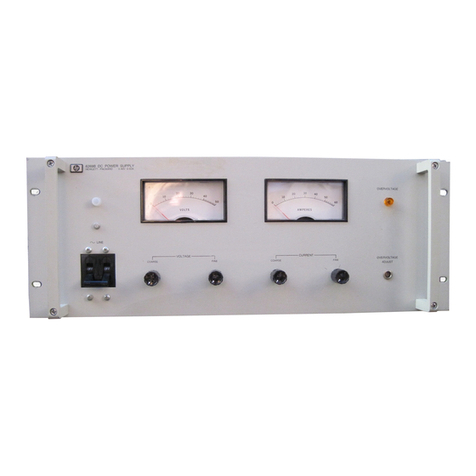
METERS:
Afront panel voltmeter,(C-700V) ~nd ammeter
,(0-1'.
SA)
are provided.
'Meters
haVe"2%
accuracy:
,
all
units
have meter c1;1llbratlng potentiometers.
i '
'''
/
OUTPUT
CONTROLS:
, , ,
,,
,
1
1
q~Tum voltar1e ancl'slngle-tpm current
controls
lo•
1,ted
on
the/.
rent panel perr~lt continuous
B;d-
ju
,
Tent
of
tlie ~utput voltage and current from
ze,~
1
to
the
maximum,
output
rating
of
the supply.
'
/:
'
OUTPUT
TERMINALS:
, , ,
' '
'
,,An
output
l:Jarrler strip
located
on the
rear
of
the
r.hassls
lncJudes de o'utput
termlnals'as
well
as
,
all
necessary
terminals for' remote erior
sensing,
remote programming, Auto-Parallel,
etc.
Either
tljeposltlve
or
negative terminal
may
be
connected
to ,the
chassis
via
a
separate
ground terminal
or
' . the
supply
may
be' operated ~loatlng
at
up to
600'
' Volts
off
ground. Front,
panel
terminals may be
used,for
monitoring purposes
cr'for
loods up to
3 Amperes.
,,
'ERROR
SENSING: ,
Error
sensing
Is
normally accompllsh~d,
at
the
front terminals If the load
Is
attached, to the front
,
or
at
the
rear
termInaIs If
the
load Is
attached
to
the
rear
terminals.,, Also, provision ls' inc,luded
on
t)le
rear
terminal strip for remote se'rislng. '
RESOLUTION:
,
,
Constant
Voltage -
60mV,minlmum
output
change
that
can
be
accomplished by the ,front panel
out-
,
,,.,~,ut
control.
Constant
Current -
o.
75inV
minim.um
output
change
that
can
be accio~pllshed
by
the
front
,
panel
output
control.
REMOTE
,PROGRAMMING:
,
Constant
voltage remote programming
ls
approx-
' !mate
ly
300 ohms per
Vo'lt,
wIth
an
accuracy
of
2%.
In
constant
current mo.de'.cif'operatlori,
the
current
can
be remotely progratnmed
at
approximately 600
ohms
per
Amp
with
6%
adcuracy. Remote program-
ming'control
ls
accomplished
either
with Input
.-eslstance
or
lnp,ut voltage.
1 '
, I
CdOL!NG:
I
,The
unit
Is
coolefl by forced
air
from
an
intema
I,
fan.
SIZE:
5-1/4"
H x
16-3/4"
D x,19"
w.
The
unit
can
be
mounted
In
a standard 19',' rack panel.
WEIGHT:
61,lbs. net. 70
lbs.
shipping.
'
'
FINISH:
Ught
gray front panel with
dark
grayc~se.
,,
1-3
