HP Compaq Presario,Presario 650 User manual

HP 560 802.11ac Access Point Installation
Guide
This document describes the procedure to install and initially configure the HP 560 802.11ac Access Point (HP 560). It is
intended for professional installers who are trained in RF installation and knowledgeable in local regulations including building
and wiring codes, safety, channel, power, indoor/outdoor restrictions, and license requirements for the country of use.
HP Part Number: 5998-8271
Published: November 2015
Edition: 1 (Software Version 6.6.2.0)

© Copyright 2015 Hewlett-Packard Development Company, L.P.
The information contained herein is subject to change without notice. The only warranties for HP products and services are set forth in the express
warranty statements accompanying such products and services. Nothing herein should be construed as constituting an additional warranty. HP shall
not be liable for technical or editorial errors or omissions contained herein.
Acknowledgments
Microsoft® and Windows® are registered trademarks of the Microsoft group of companies.
Mozilla® and Firefox® are registered trademarks of the Mozilla Foundation.
Warranty
WARRANTY STATEMENT: To obtain a copy of the warranty for this product, see the warranty information website:
www.hp.com/support/Networking-Warranties

Contents
1 Overview..................................................................................................4
Product models.........................................................................................................................4
Operational modes...................................................................................................................4
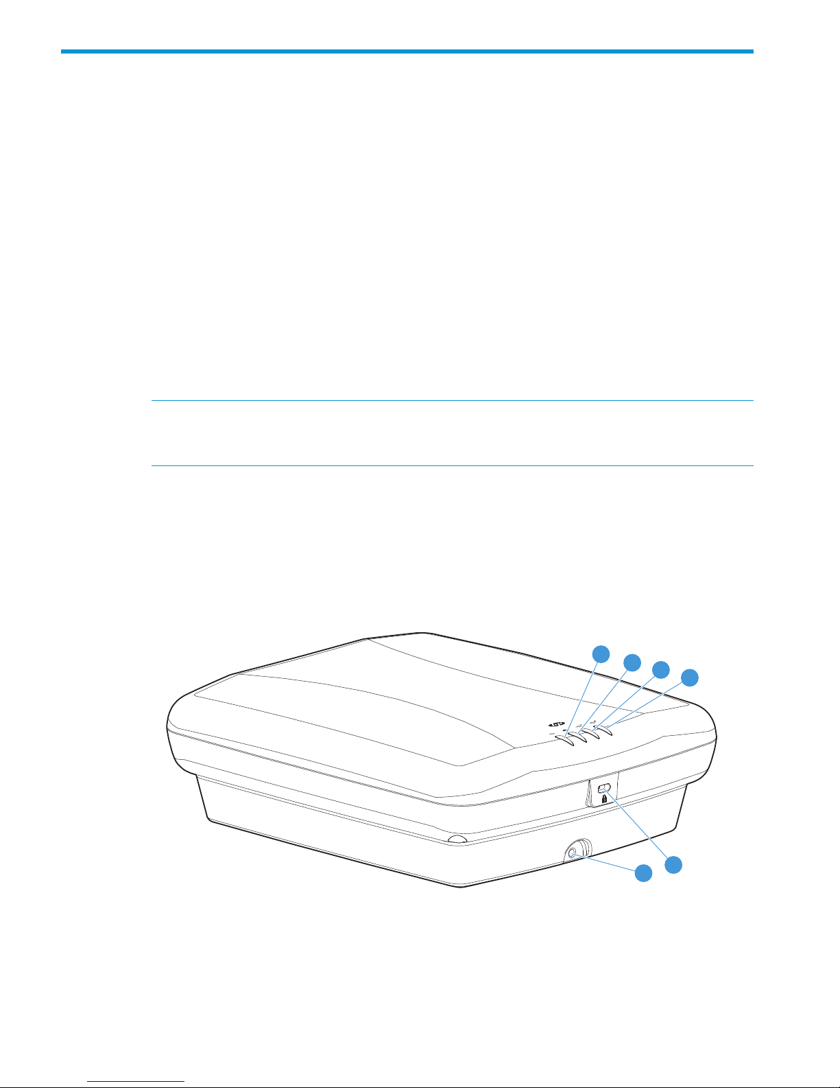
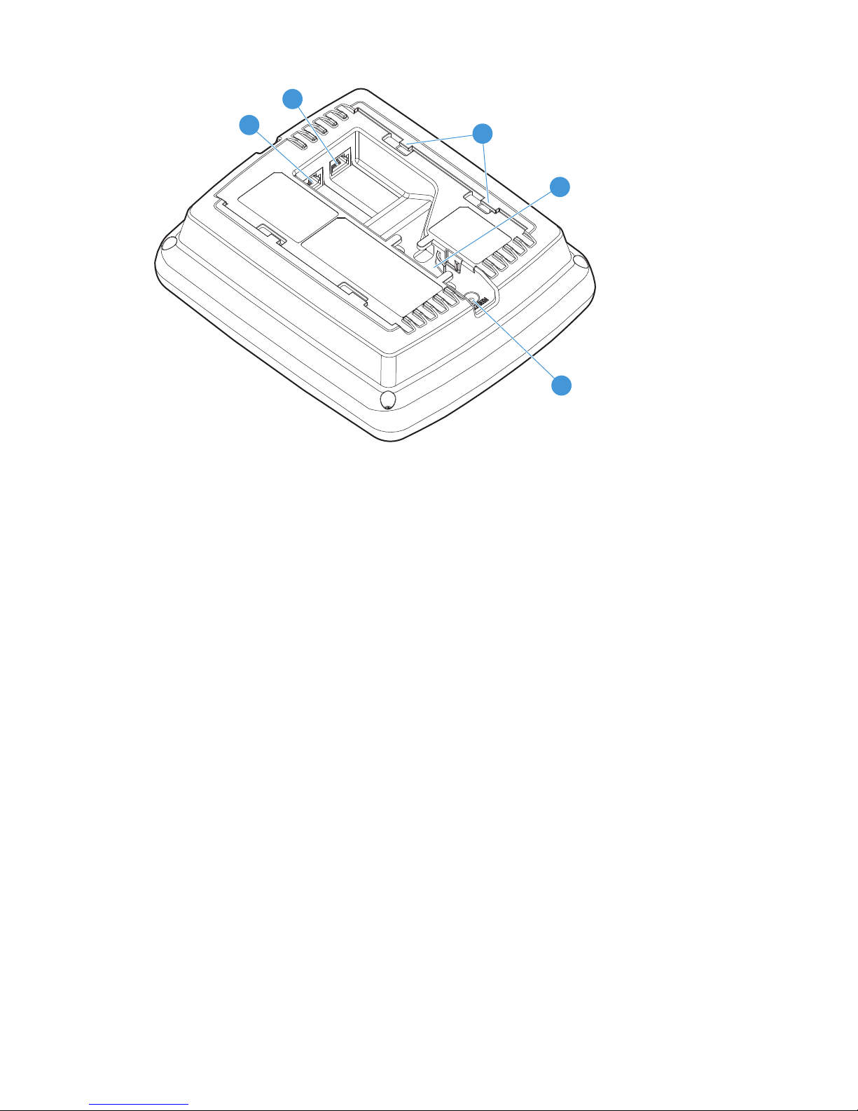
Hardware overview...................................................................................................................4
Ports.......................................................................................................................................5
Radios....................................................................................................................................5
Antennas.................................................................................................................................5
Power.....................................................................................................................................6
Reset button.............................................................................................................................6
Status LEDs..............................................................................................................................6
2 Installing the HP 560..................................................................................7
Unpacking the product..............................................................................................................7
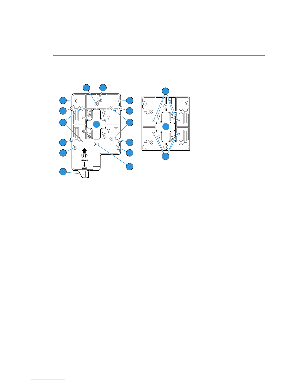
Installing on a wall...................................................................................................................8
Installing on an electrical box ....................................................................................................8
Installing on a suspended ceiling................................................................................................9
Installing in a plenum..............................................................................................................10
Attaching the HP 560..............................................................................................................10
Securing the HP 560...............................................................................................................10
Removing the HP 560.............................................................................................................11
3 Using the HP 560 with a controller.............................................................12
HP 560 status LED states in controlled mode...............................................................................12
4 Using the HP 560 as a standalone AP........................................................14
HP 560 status LED states in autonomous mode...........................................................................14
Configuring the HP 560 for autonomous mode...........................................................................14
Configure your computer....................................................................................................14
Connect the cables and power on the HP 560.......................................................................15
Switch the HP 560 to autonomous mode...............................................................................15
Log in...............................................................................................................................15
Configure wireless protection...............................................................................................15
Assign an IP address to the HP 560.....................................................................................16
Testing the wireless network.................................................................................................16
Performing additional configuration......................................................................................16
5 Support and other resources......................................................................17
Contacting HP........................................................................................................................17
Related information.................................................................................................................17
Websites..........................................................................................................................17
Controller part numbers...........................................................................................................17
Typographic conventions.........................................................................................................18
6 Documentation feedback...........................................................................19
A Regulatory information..............................................................................20
Plenum installation..................................................................................................................20
Turkey RoHS material content declaration...................................................................................20
Ukraine RoHS material content declaration................................................................................20
Contents 3

1 Overview
The HP 560 is a dual-band 802.11a/b/g/n/ac Access Point (AP). It is managed through its
web-based management tool using Microsoft Internet Explorer 9.0+ or Mozilla Firefox 15+.
Product models
HP 560: J9846A (WW), J9845A (AM), J9847A (JP), J9848A (IL)
Operational modes
The HP 560 can operate in either autonomous mode or controlled mode.
•Autonomous mode: The HP 560 operates as a stand-alone device providing wireless services.
•Controlled mode: The HP 560 provides wireless services under the management of a controller
from one of the following product families:
◦MSM720, MSM760, MSM765 zl, MSM775 zl
◦HP 10500/7500, HP 830, HP 870, HP WX5002/WX5004
NOTE: Both controller families cannot coexist on the same network. HP 10500/7500, HP
830, HP 870, and HP WX5002/WX5004 Controllers are not compatible with HP MSM7xx
Controllers.
For more information, see “Using the HP 560 with a controller” (page 12) and “Controller
part numbers” (page 17).
Hardware overview
Figure 1 Front and bottom view
1
23
4
5
6
4. Radio 2 LED1. Power/System OK LED
5. Cable lock hole2. Ethernet LED
6. Retention screw hole3. Radio 1 LED
4 Overview

Figure 2 Back view
1
2
3
4
5
4. Cable channel1. Ethernet port
5. Reset button2. Console port
3. AP bracket tab
Ports
The following ports are located on the back of the HP 560 as shown in Figure 2 (page 5):
•Ethernet port: Auto-sensing 10/100/1000 BaseT Ethernet port with RJ-45 connector. This port
supports IEEE 802.3af and 802.3at Power over Ethernet (PoE).
•Console port: A standard serial port with RJ-45 connector. To connect to a computer, use a
standard serial cable. For more information, see “Console Ports” in the HP MSM APs
Configuration Guide.
Radios
The HP 560 has two radios:
•Radio 1: Supports 5 GHz 802.11a/n/ac.
•Radio 2: Supports 2.4 GHz 802.11b/g/n.
Antennas
The HP 560 has two integrated 3-element MIMO antennas.
Ports 5

Power
The HP 560 is powered via port 1, using either PoE or PoE+.
Power operating mode
By default, the HP 560 dynamically determines the available input power via hardware detection
or LLDP, and sets radio operation as follows:
•If the available power is 802.3af: The 2.4 GHz radio operates in 2x2:2 mode, and the 5
GHz radio operates in 3x3:3 mode.
•If the available power is 802.3at: The 2.4 GHz and 5 GHz radios both operate in 3x3:3
mode.
If you are using a non-standard 802.3af+ or 802.3at+ device to power the HP 560, automatic
detection might be unable to determine the actual available power. In this case, you can set the
power operating mode to High, which forces the HP 560 to operate in full-power mode (both
radios operate in 3x3:3 mode).
To set the power operating mode:
•If the HP 560 is operating in controlled mode, on the controller, select Controlled APs >HP560
>> Configuration >Power.
•If the HP 560 is operating in autonomous mode, select Configuration >Power.
Reset button
The reset button is accessible via a hole on the back of the HP 560. To reset the HP 560, insert a
paper clip into the reset button hole, and press and quickly release the button. To reset the HP 560
to factory defaults, press and hold the button until the status LEDs flash three times, and then release.
Status LEDs
There are four status LEDs on the front of the HP 560:
•Power/System OK
•Ethernet
•Radio 1
•Radio 2
LED behavior varies, depending on the HP 560 operating in controlled or autonomous mode. See
“HP 560 status LED states in controlled mode” (page 12) and “HP 560 status LED states in
autonomous mode” (page 14).
6 Overview

2 Installing the HP 560
The HP 560 is designed for indoor installation on a desktop, wall, ceiling, or in a plenum. You
are responsible for ensuring that installation and use comply with local safety and radio regulations.
IMPORTANT: This device requires professional installation. Consult a professional installer trained
in RF installation and knowledgeable in local regulations including:
•Building and wiring codes.
•Safety regulations.
•Channel, power, and indoor/outdoor restrictions.
•License requirements for the intended country of operation.
It is important to identify known RF absorbers, reflectors, and interference sources in the environment
while planing your installation.
Unpacking the product
Inspect the package contents and verify that they are free from defects. The package contains:
•An HP 560.
•An AP mounting bracket.
•A padlock bracket.
•Two sets of AP bracket T-bar clips with screws.
•Two mounting screws with wall anchors.
•A retention screw.
•An adapter bracket. (If you are replacing an existing device with an HP 560, you can use
this bracket to connect the HP 560 mounting bracket to the existing mounting bracket.)
•Documentation.
NOTE: The AP bracket is two-sided. Install the HP 560 on the side with the UP arrow. The other
side, with the T-bar clip screw holes, faces the wall or T-bar. The AP bracket is mounted first, and
then the HP 560 is attached to the bracket.
Unpacking the product 7

Installing on a wall
When installing the HP 560 on a wall, ensure that the mounting surface and the fasteners you use
can support at least 0.9 kg (2 lb). Allow extra weight for cables.
1. Hold the mounting bracket, with the UP arrow pointing up, against the wall where you want
to install it. Mark the location of the screw holes (wall anchors) and the cutout area.
NOTE: The holes that you use depend on the mounting surface. See Figure 3 (page 8).
Figure 3 AP mounting bracket
1
1
23
4
4
5
7
1
1
4
4
5
2
6
8
8
6
5. Drywall mounting holes1. Adapter bracket mounting holes
6. Cutout area2. Electric box mounting holes
7. AP bracket lock tab3. AP bracket latch
8. T-bar clip screw holes4. AP retention tabs
2. Drill two holes for the screws or wall anchors, typically 4.7 mm (3/16 inch) in diameter.
3. If necessary, drill a hole for the Ethernet cable in the marked cutout area.
Alternately, you can feed the Ethernet cable from above and through the AP cable channel.
4. If you are using wall anchors, insert them into the holes that you drilled, and tap them flush
with the wall surface.
5. If you are running the Ethernet cable through the wall, pull it through the hole in the wall and
the AP bracket.
6. Use the mounting screws to attach the AP bracket to the wall.
7. Proceed to “Attaching the HP 560” (page 10).
Installing on an electrical box
1. Disconnect power from the electrical box and take any other needed security precautions.
2. Remove the electrical box cover and any contents.
3. Pull the Ethernet cable down into the box and through the hole in the AP bracket.
4. Hold the AP bracket with the UP arrow pointing up against the box, and use the countersunk
screws to attach the AP bracket.
5. Proceed to “Attaching the HP 560” (page 10).
8 Installing the HP 560

Installing on a suspended ceiling
Two sets of T-bar clips are included for installing the HP 560 on a suspended ceiling.
•If the ceiling tiles are recessed, use the 12.5 mm set of T-bar clips (shown at the top of
Figure 4 (page 9)).
•If the ceiling tiles are flush mount, use the 4.5 mm set of T-bar clips (shown at the bottom of
Figure 4 (page 9)).
WARNING! Areas above suspended ceilings can contain dangerous electrical cabling, gas
pipes, and other hazards. Make whatever safety arrangements are needed to ensure that you can
work safely above the suspended ceiling. HP recommends that you use a non-conductive step
ladder, such as one made of fiberglass.
1. Slide one of the T-bar clips into the AP bracket T-bar slot. Attach it using two self-tapping
screws. Select the bracket screw holes marked according to the width of your T-bar: 9/16
inch, 15/16 inch, or 1.5 inch. (The other T-bar clip attaches to the AP Bracket from above
the suspended ceiling, after the bracket is in place on the T-bar.)
Figure 4 Attaching T-bar clips to the AP bracket
1 2 23 3
44
3. AP bracket T-bar slot1. AP bracket
4. Flat tile 4.5 mm T-bar clip2. Recessed tile 12.5 mm T-bar clip
2. Remove/relocate two ceiling tiles, one on each side of the T-bar on which you are installing
the AP bracket.
3. Carrying a screw driver, the AP bracket with T-bar clip attached, the other T-bar clip, and two
screws, position yourself above the T-bar on which you are installing the AP bracket.
4. Attach the AP bracket onto the T-bar, slide the other T-bar clip into the AP bracket T-bar clip
slot, and then use the screws to attach it such that both T-bar clips grip the T-bar.
5. Tighten all four T-bar clip screws fully and verify that the AP bracket is securely anchored to
the T-bar from both sides.
6. Re-install the ceiling tile through which you will pass the Ethernet cable.
7. Using the cutout area in the AP bracket as a guide, drill or cut a hole in the ceiling tile large
enough to pass the Ethernet connector through.
Alternatively, you can run a cable under the ceiling tile and through the AP cable channel.
Installing on a suspended ceiling 9

8. If the Ethernet cable is above the ceiling, feed the Ethernet cable down through the hole in
the tile and through the hole in the AP bracket. Pull through an extra 60 cm (2 feet) of cable.
9. Proceed to “Attaching the HP 560” (page 10).
Installing in a plenum
To install the device in a plenum, you must use plenum-rated cables and attachment hardware. HP
recommends that you install the HP 560 in a similar orientation as in a ceiling installation. However,
a qualified installer can determine how to install and secure the HP 560 in a plenum in an
appropriate and safe manner. See “Plenum installation” (page 20) and “Installing on a suspended
ceiling” (page 9).
Attaching the HP 560
1. Connect the Ethernet cable to the HP 560.
2. Hold the bottom of the HP 560 against the AP bracket, aligning the AP tab slots with the AP
retention tabs on the AP bracket. Pull back any Ethernet cable slack at the same time.
3. While firmly holding the HP 560 against the AP bracket, slide the HP 560 toward the AP
bracket lock tab so that the HP 560 snaps onto the bracket. Do not let go of the HP 560 until
you confirm that it is securely in place.
Figure 5 Attaching the HP 560 to the AP bracket
1 2 3
4
3. AP tab slots snapped onto AP bracket retention tabs1. Lock tab
4. AP bracket latch2. AP bracket
Securing the HP 560
HP strongly recommends that as soon as the HP 560 is installed, you install the retention screw
that anchors the AP bracket to the HP 560 (callout 2 on Figure 6 (page 11)).
Optionally, attach a cable lock in the cable lock hole or insert the tab of the supplied AP padlock
bracket into the cable lock hole, and then align the AP padlock bracket hole with the AP bracket
lock hole and install a user-supplied padlock.
10 Installing the HP 560

Figure 6 Retention screw and padlock bracket
123
4
5
6
4. Padlock hole1. AP bracket
5. AP padlock bracket2. Retention screw
6. Cable lock hole3. AP bracket lock tab
Removing the HP 560
To remove the HP 560 from the bracket:
1. Remove any locks and remove the retention screw.
2. While carefully holding the HP 560, insert a flat screwdriver into the cable channel between
the channel wall and the AP bracket latch, releasing the HP 560 from the bracket, while being
careful to retain grip on the HP 560 as you slide it away from the AP bracket lock tab.
3. Disconnect the Ethernet cable from the HP 560.
Removing the HP 560 11

3 Using the HP 560 with a controller
The HP 560 is typically operated in controlled mode and is managed using one of the following
controllers:
•HP MSM720, MSM760, MSM765 zl, MSM775 zl
•HP 10500/7500, HP 830, HP 870, HP WX5002/WX5004
NOTE: Both controller families cannot coexist on the same network. HP 10500/7500, HP 830,
HP 870, and HP WX5002/WX5004 Controllers are not compatible with HP MSM7xx Controllers.
IMPORTANT: If your HP 560 was ever used with an HP 10500/7500, HP 830, HP 850, HP
870, or HP WX5002/WX5004 controller, before you can use it with an MSM controller, you
must follow the procedures described in Instructions for Converting an Access Point from
Unified-Controlled to Using MSM Software, available at www.hp.com/support/manuals.
If default settings are used on the HP 560 and the controller, and both devices are on the same
subnet, when powered on, the HP 560 automatically discovers a controller and establishes a
secure connection to it. No further configuration is required. The controller manages the HP 560
and provides all configuration settings.
Once the discovery process is complete, and the secure management tunnel is established, the HP
560 power LED remains on and the Ethernet and radio LEDs flash to indicate the presence of
traffic.
For more information on using the HP 560 with a controller, see:
•HP MSM Controllers Configuration Guide
•HP 830 Series PoE+ Unified Wired-WLAN Switch and HP 10500/7500 20G Unified
Wired-WLAN Module Fundamentals Configuration Guide
•H3C WX Series Access Controller Module Basic Configuration Guide
•HP 870 Unified Wired-WLAN Appliance Switch Switching Engine Fundamentals Configuration
Guide
HP 560 status LED states in controlled mode
DescriptionStatus LED state
The HP 560 is starting up.Power/System OK LED flashes every
two seconds.
The HP 560 is looking for an IP address, or building the list of VLANs on which
to perform controller discovery. The management tool is available until discovery
occurs.
Power/System OK LED flashes once
per second.
The HP 560 has obtained an IP address and is attempting to discover a
controller.
Power/System OK, Ethernet, and
Radio LEDs flash in sequence from left
to right.
The HP 560 has found a controller and is attempting to establish a secure
management tunnel with it.
Power/System OK LED is on, Ethernet
and Radio LEDs flash alternately.
The HP 560 has received a discovery reply from two or more controllers with
the same priority setting. It cannot connect with either controller until the conflict
is resolved by adjusting the discovery priority setting on at least on controller.
Power/System OK and Ethernet LEDs
flash alternately and quickly, Radio
LEDs are off.
12 Using the HP 560 with a controller

DescriptionStatus LED state
The HP 560 is attempting to establish a local mesh link to a master node.Power/System OK and Radio LEDs
flash slowly.
The HP 560 is attempting to establish wired connectivity.Power/System OK and Ethernet LEDs
flash slowly.
HP 560 status LED states in controlled mode 13

4 Using the HP 560 as a standalone AP
In autonomous mode, the HP 560 operates as a standalone AP. You configure and manage it
using its web-based management tool, as described in this section.
The management tool is organized with menus and sub-menus. Instructions for making menu
selections, such as “select Network > DNS” instruct you to select the Network menu, and then the
DNS sub-menu, as follows:
HP 560 status LED states in autonomous mode
DescriptionStateLED
The HP 560 has no power.OffPower/System OK
The HP 560 is starting up. A power LED that continues to flash after
several minutes indicates that the software failed to load. If this occurs,
Flashing
reset or power cycle the HP 560. If this condition persists, contact HP
customer support.
The HP 560 is fully operational.On
The port is not connected or there is no activity.OffEthernet
The port is transmitting or receiving data.Flashing
The radio is transmitting or receiving data.FlashingRadio
Configuring the HP 560 for autonomous mode
This procedure describes how to set a factory-default HP 560 to autonomous mode, and then
perform its initial configuration that enables you to establish a wireless connection with the HP
560.
IMPORTANT: If your HP 560 was ever used with an HP 10500/7500, HP 830, HP 850, HP
870, or HP WX5002/WX5004 controller, before you can use it with an MSM controller, you
must follow the procedures described in Instructions for Converting an Access Point from
Unified-Controlled to Using MSM Software, available at www.hp.com/support/manuals.
In autonomous mode, the HP 560 is managed via its web-based management tool using Microsoft
Internet Explorer 9+ or Mozilla Firefox 15+.
CAUTION: Wireless protection: A factory-default HP 560 that has been switched to autonomous
mode has all wireless protection options disabled. HP recommends that you configure your HP
560 for wireless protection as described in “Configure wireless protection” (page 15). See also
“Wireless protection” in the HP MSM APs Configuration Guide.
NOTE: Do not power on the HP 560 until directed to do so.
Configure your computer
1. Disconnect your computer LAN port and configure it to use the static IP address 192.168.1.2
and the subnet mask 255.255.255.0. Set the default gateway to 192.168.1.1 and DNS server
to 192.168.1.1.
2. Disable any wireless connection on your computer.
14 Using the HP 560 as a standalone AP

Connect the cables and power on the HP 560
The HP 560 is powered via port 1, using either PoE or PoE+.
1. Connect the cables:
•If using a PoE switch, use Ethernet cables to connect your computer and the HP 560 to
an unused factory-default PoE switch.
•If using a PoE injector, use Ethernet cables to connect your computer to the data in port
of the PoE injector and the HP 560 to the data and power out port of the PoE injector.
2. Power on the HP 560 by powering on the PoE switch or injector.
Initially, the HP 560 power LED flashes once every two seconds.
3. Wait approximately a minute until the power LED begins flashing once per second before
proceeding to the next step.
For information about PoE, see “Power” (page 6).
Switch the HP 560 to autonomous mode
NOTE: A factory-default HP 560 is assumed.
1. In your web browser, enter the address: https://192.168.1.1.
2. A security certificate warning is displayed the first time you connect to the management tool.
This is expected behavior. Select whatever option is needed in your web browser to continue
to the management tool.
3. On the Login page, specify admin for both Username and Password, and then select Login.
The HP 560 management tool home page opens.
IMPORTANT: If you do not see the Switch to Autonomous Mode button, you must follow the
procedures in the separate document Instructions for Converting an Access Point from
Unified-Controlled to Using MSM Software, even if your HP 560 has never been adopted by
a unified controller.
4. Select Switch to Autonomous Mode and confirm the change.
The HP 560 restarts in autonomous mode.
NOTE: To avoid a delay after switching modes, clear the ARP (address resolution protocol) cache
on your computer. For example, from the Windows Start menu, select Run and enter arp -d, and
then select OK.
Log in
1. Wait until the Power/System OK LED remains on.
2. On the Login page, specify admin for both Username and Password and then select Login.
3. Follow the License and Registration instructions.
4. If a Country prompt appears, select the country in which the HP 560 will operate.
CAUTION: To ensure compliance, you must select the correct country.
5. When prompted, HP recommends that you change the password from the default. Passwords
must be at least six characters long and include four different characters.
Configure wireless protection
HP recommends that you configure wireless protection. This section describes how to configure
WPA or WPA2 wireless protection. For more information, see “Wireless protection” in the HP
MSM APs Configuration Guide.
Configuring the HP 560 for autonomous mode 15

To configure WPA or WPA2 protection on the default wireless network:
1. Select VSC >HP, and then enable Wireless protection and set it to WPA.
2. Set Mode, to WPA or WPA2.
3. Set Key source to Preshared key and specify a key of at least 20 characters.
4. Click Save.
Assign an IP address to the HP 560
By default, the HP 560 operates as a DHCP client. This means that if you connect the HP 560 to
a network that has a DHCP server, the HP 560 automatically receives a new IP address in place
of its default address of 192.168.1.1. You can find the IP address assigned to the HP 560 by
looking for its Ethernet base MAC address in the DHCP server log. (The HP 560 Ethernet MAC
address is printed on the HP 560 label identified as LAN MAC, and listed on the management
tool Home page as Ethernet base MAC address.)
Another option is to assign a static IP address to the HP 560 using the management tool as follows:
1. Select Network >DNS, and set the DNS server address. Select Save.
2. Select Network >Ports >Bridge port.
3. Select Static, and then Configure. For IP address, set an address that is on the same subnet
as the network to which the HP 560 will connect after installation. Respect any DHCP
server-mandated static address ranges. Also set Mask and Default gateway.
4. Select Save. Your connection to the management tool is lost. You can reconnect to the
management tool by specifying the new static IP address.
Testing the wireless network
In this example, the network to which the HP 517 is connected must have a DHCP server and an
Internet connection.
1. Disconnect your computer from the PoE switch or injector.
2. Power off the HP 560 by disconnecting the Ethernet cable from the HP 560.
3. Use a standard Ethernet cable to connect the switch or the data in port on the injector to the
network.
4. Reconnect and power on the HP 560. Use a standard Ethernet cable to reconnect the HP 560
to the PoE switch or the data and power out port on the injector.
5. Enable the wireless network interface on your computer, and verify that it is set to obtain an
IP address automatically.
6. By default, the HP 560 creates a wireless network named HP in the 5 GHz band for 802.11n
and 802.11a users. Connect your computer to this wireless network, specifying the preshared
key you set in “Configure wireless protection” (page 15).
7. Confirm that you can browse the Internet using the wireless network.
Performing additional configuration
Configure your computer LAN port and connect it to the same network as the HP 560. Re-launch
the HP 560 management tool at https://IP address where IP address is the HP 560 IP
address assigned in “Assign an IP address to the HP 560” (page 16).
16 Using the HP 560 as a standalone AP

5 Support and other resources
Contacting HP
For worldwide technical support information, see the HP support website:
www.hp.com/support
Before contacting HP, collect the following information:
•Product model names and numbers
•Technical support registration number (if applicable)
•Product serial numbers
•Error messages
•Operating system type and revision level
•Detailed questions
Related information
The following documents provide related information:
•HP 560 802.11ac Access Point Configuration and Administration Guide
•MSM Controllers Configuration Guide
•HP 830 Series PoE+ Unified Wired-WLAN Switch and HP 10500/7500 20G Unified
Wired-WLAN Module Fundamentals Configuration Guide
•H3C WX Series Access Controller Module Basic Configuration Guide
•HP 870 Unified Wired-WLAN Appliance Switch Switching Engine Fundamentals Configuration
Guide
•Instructions for Converting an Access Point from Unified-Controlled to Using MSM Software
You can find these documents on the Manuals page of the HP Support Center website:
www.hp.com/support/manuals
Enter your product name or number, and click GO.
Websites
•HP Networking website: www.hp.com/networking/
Controller part numbers
•HP 10500/7500: JG639A, JG645A (TAA)
•HP 830: 24P - JG640A, JG646A (TAA); 8P - JG641A, JG647A (TAA)
•HP 870: JG723A, JG725A (TAA)
•HP WX5002: JD447B
•HP WX5004: JD448B
•HP MSM720: J9693A, J9694A, J9695A (TAA), J9696A (TAA)
•HP MSM760: J9420A, J9421A
•HP MSM765 zl: J9370A
•HP MSM775 zl: J9840A
Contacting HP 17

Typographic conventions
Table 1 Document conventions
ElementConvention
Cross-reference linksBlue text: Table 1 (page 18)
Website addressesBlue, underlined text: www.hp.com
Bold text •Keys that are pressed
•Text typed into a GUI element, such as a box
•GUI elements that are clicked or selected, such as menu
and list items, buttons, tabs, and check boxes
Text emphasisItalic text
Monospace text •File and directory names
•System output
•Code
•Commands, their arguments, and argument values
Monospace, italic text •Code variables
•Command variables
Emphasized monospace textMonospace, bold text
WARNING! Indicates that failure to follow directions could result in bodily harm or death.
CAUTION: Indicates that failure to follow directions could result in damage to equipment or data.
IMPORTANT: Provides clarifying information or specific instructions.
NOTE: Provides additional information.
18 Support and other resources

6 Documentation feedback
HP is committed to providing documentation that meets your needs. To help us improve the
documentation, send any errors, suggestions, or comments to Documentation Feedback
([email protected]). Include the document title and part number, version number, or the URL
when submitting your feedback.
19

A Regulatory information
For important safety, environmental, and regulatory information, see Safety and Compliance
Information for Server, Storage, Power, Networking, and Rack Products, available at http://
www.hp.com/support/Safety-Compliance-EnterpriseProducts, and also the regulatory information
in the HP MSM 560 802.11ac Access Point Quickstart.
Plenum installation
The HP 560 can be installed in a plenum. The HP 560 is suitable for use in environmental air
space in accordance with Section 300-22(C) of the National Electrical Code, and Sections 2-128,
12-010(3) and 12-100 of the Canadian Electrical Code, Part 1, CSA C22.1.
Turkey RoHS material content declaration
Türkiye Cumhuriyeti: EEE Yönetmeliğine Uygundur
Ukraine RoHS material content declaration
Обладнання відповідає вимогам Технічного регламенту щодо обмеження використання деяких
небезпечних речовин в електричному та електронному обладнанні, затвердженого постановою
Кабінету Міністрів України від 3 грудня 2008 № 1057
20 Regulatory information
Other manuals for Compaq Presario,Presario 650
3
Table of contents
Other HP Wireless Access Point manuals
Popular Wireless Access Point manuals by other brands

Sprint
Sprint Magic Box TREBL Design Requirements Document

TRENDnet
TRENDnet TEW-638PAP Quick installation guide

D-Link
D-Link DWL-7200AP - AirPremier AG - Wireless Access... manual

Aruba
Aruba Instant On AP22 installation guide

SkyPilot
SkyPilot SkyAccess DualBand Installation

EnGenius
EnGenius ENH500 user manual