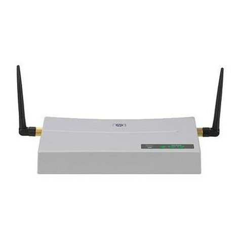
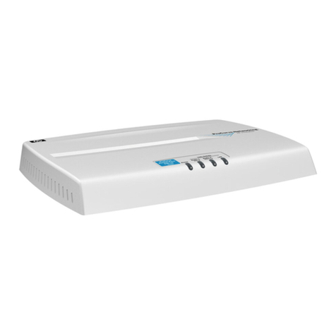
HP WL520 User manual

contents
contentscontents
1
11 introducing the hpintroducing the hp WL520
WL520520 enterprise access point
enterprise access pointenterprise access point
2
2igu p
configuring the hpconfiguring the hpWL520
WL520WL520enterprise access point
enterprise access pointenterprise access point
hp WL520 enterprise access point user guide
contents
1 introducing the hp WL
introducing the hp WL520 enterprise access point
wireless networking concepts . . . . . . . . . . . . . . . . . . . . . . . . . . . . . . . . . . . . . . . . . . 1-1
management and monitoring capabilities . . . . . . . . . . . . . . . . . . . . . . . . . . . . . . . . . . 1-2
http interface . . . . . . . . . . . . . . . . . . . . . . . . . . . . . . . . . . . . . . . . . . . . . . . . . . . . . . . . 1-2
command line interface . . . . . . . . . . . . . . . . . . . . . . . . . . . . . . . . . . . . . . . . . . . . . . . . . 1-2
802.11b versus 802.11a networks . . . . . . . . . . . . . . . . . . . . . . . . . . . . . . . . . . . . . 1-3
feature list . . . . . . . . . . . . . . . . . . . . . . . . . . . . . . . . . . . . . . . . . . . . . . . . . . . . . . . . . . 1-3
cell size and coverage area . . . . . . . . . . . . . . . . . . . . . . . . . . . . . . . . . . . . . . . . . . . . . . 1-4
auto channel select . . . . . . . . . . . . . . . . . . . . . . . . . . . . . . . . . . . . . . . . . . . . . . . . . . . . 1-5
installation and initialization . . . . . . . . . . . . . . . . . . . . . . . . . . . . . . . . . . . . . . . . . . 1-5
2 configuring the hp WL520 enterprise access point2conf ring the h
overview . . . . . . . . . . . . . . . . . . . . . . . . . . . . . . . . . . . . . . . . . . . . . . . . . . . . . . . 2-1
prerequisites . . . . . . . . . . . . . . . . . . . . . . . . . . . . . . . . . . . . . . . . . . . . . . . . . . . . . 2-2
set basic configuration parameters . . . . . . . . . . . . . . . . . . . . . . . . . . . . . . . . . . . . . . 2-2
download the latest software . . . . . . . . . . . . . . . . . . . . . . . . . . . . . . . . . . . . . . . . . . 2-7
setup your tftp server . . . . . . . . . . . . . . . . . . . . . . . . . . . . . . . . . . . . . . . . . . . . . . . . . . . .2-7
download updates to your tftp server from the web interface . . . . . . . . . . . . . . . . . . . . . . . . . .2-7
backup your hp WL520 configuration file . . . . . . . . . . . . . . . . . . . . . . . . . . . . . . . . . . . . . 2-8
copy a configuration file from anotherhp WL520 unit . . . . . . . . . . . . . . . . . . . . . . . . . . . . . 2-8
other network settings . . . . . . . . . . . . . . . . . . . . . . . . . . . . . . . . . . . . . . . . . . . . . . 2-9
configure the hp WL520 device as a dhcp server . . . . . . . . . . . . . . . . . . . . . . . . . . . . . . . . 2-9
maintain 802.11b client connections using link integrity . . . . . . . . . . . . . . . . . . . . . . . . . . . 2-10
change your wireless interface settings . . . . . . . . . . . . . . . . . . . . . . . . . . . . . . . . . . . 2-11
802.11a wireless interface card . . . . . . . . . . . . . . . . . . . . . . . . . . . . . . . . . . . . . . . . . . 2-11
802.11b wireless interface card . . . . . . . . . . . . . . . . . . . . . . . . . . . . . . . . . . . . . . . . . . 2-12
auto channel select (acs) . . . . . . . . . . . . . . . . . . . . . . . . . . . . . . . . . . . . . . . . . . . . . . . 2-13
distance between aps. . . . . . . . . . . . . . . . . . . . . . . . . . . . . . . . . . . . . . . . . . . . . . . . . 2-14
multicast rate . . . . . . . . . . . . . . . . . . . . . . . . . . . . . . . . . . . . . . . . . . . . . . . . . . . . . . . 2-15
ethernet settings . . . . . . . . . . . . . . . . . . . . . . . . . . . . . . . . . . . . . . . . . . . . . . . . . 2-16
set ethernet speed and transmission mode . . . . . . . . . . . . . . . . . . . . . . . . . . . . . . . . . . . . 2-16
configure your management interfaces . . . . . . . . . . . . . . . . . . . . . . . . . . . . . . . . . . . 2-16
set http interface management services . . . . . . . . . . . . . . . . . . . . . . . . . . . . . . . . . . . . . . 2-17
configure serial port interface settings . . . . . . . . . . . . . . . . . . . . . . . . . . . . . . . . . . . . . . . 2-17
i

3
33 magi hp
managing the hpmanaging the hp WL
WL520WL520 enterprise access point
enterprise access pointenterprise access point
4
44 gva atures
configuring advanced featuresconfiguring advanced features
other security configuration settings . . . . . . . . . . . . . . . . . . . . . . . . . . . . . . . . . . . . . 2-17
configure your mac (address) access control table . . . . . . . . . . . . . . . . . . . . . . . . . . . . . . . 2-17
radius authentication settings . . . . . . . . . . . . . . . . . . . . . . . . . . . . . . . . . . . . . . . . . . . . . 2-18
IEEE 802.1x security mode. . . . . . . . . . . . . . . . . . . . . . . . . . . . . . . . . . . . . . . . . . . . . . 2-19
if you encounter problems... . . . . . . . . . . . . . . . . . . . . . . . . . . . . . . . . . . . . . . . . . 2-21
an ng the 5203 managing the hp WL520 enterprise access point
in this chapter . . . . . . . . . . . . . . . . . . . . . . . . . . . . . . . . . . . . . . . . . . . . . . . . . . . .3-1
management interface . . . . . . . . . . . . . . . . . . . . . . . . . . . . . . . . . . . . . . . . . . . . . . 3-2
monitoring network statistics . . . . . . . . . . . . . . . . . . . . . . . . . . . . . . . . . . . . . . . . . . 3-3
view hardware/software component information . . . . . . . . . . . . . . . . . . . . . . . . . . . . . . . . . 3-3
monitoring icmp statistics . . . . . . . . . . . . . . . . . . . . . . . . . . . . . . . . . . . . . . . . . . . . . . . . 3-4
monitoring ip/arp statistics . . . . . . . . . . . . . . . . . . . . . . . . . . . . . . . . . . . . . . . . . . . . . . . 3-4
monitoring learn table statistics. . . . . . . . . . . . . . . . . . . . . . . . . . . . . . . . . . . . . . . . . . . . . 3-4
monitoring iapp statistics . . . . . . . . . . . . . . . . . . . . . . . . . . . . . . . . . . . . . . . . . . . . . . . . 3-5
monitoring radius server statistics . . . . . . . . . . . . . . . . . . . . . . . . . . . . . . . . . . . . . . . . . . . 3-5
monitoring interfaces statistics . . . . . . . . . . . . . . . . . . . . . . . . . . . . . . . . . . . . . . . . . . . . . 3-6
monitoring remote link test statistics . . . . . . . . . . . . . . . . . . . . . . . . . . . . . . . . . . . . . . . . . . 3-6
issuing system commands . . . . . . . . . . . . . . . . . . . . . . . . . . . . . . . . . . . . . . . . . . . . 3-7
download . . . . . . . . . . . . . . . . . . . . . . . . . . . . . . . . . . . . . . . . . . . . . . . . . . . . . . . . . . 3-8
upload . . . . . . . . . . . . . . . . . . . . . . . . . . . . . . . . . . . . . . . . . . . . . . . . . . . . . . . . . . . . 3-9
reboot . . . . . . . . . . . . . . . . . . . . . . . . . . . . . . . . . . . . . . . . . . . . . . . . . . . . . . . . . . . . 3-9
reset. . . . . . . . . . . . . . . . . . . . . . . . . . . . . . . . . . . . . . . . . . . . . . . . . . . . . . . . . . . . . 3-10
help link . . . . . . . . . . . . . . . . . . . . . . . . . . . . . . . . . . . . . . . . . . . . . . . . . . . . . . . . . . 3-10
4 configuring advanced featuresconfigurin ad nced fe
network settings . . . . . . . . . . . . . . . . . . . . . . . . . . . . . . . . . . . . . . . . . . . . . . . . . . 4-2
advanced dhcp server configuration . . . . . . . . . . . . . . . . . . . . . . . . . . . . . . . . . . . . . . . . . 4-2
dhcp ip pool table settings . . . . . . . . . . . . . . . . . . . . . . . . . . . . . . . . . . . . . . . . . . . . . . . 4-2
link integrity settings. . . . . . . . . . . . . . . . . . . . . . . . . . . . . . . . . . . . . . . . . . . . . . . . . . . . 4-3
vlan support . . . . . . . . . . . . . . . . . . . . . . . . . . . . . . . . . . . . . . . . . . . . . . . . . . . . .4-4
typical vlan configurations.. . . . . . . . . . . . . . . . . . . . . . . . . . . . . . . . . . . . . . . . . . . . . . . 4-4
vlan workgroups and traffic management . . . . . . . . . . . . . . . . . . . . . . . . . . . . . . . . . . . . . . 4-5
typical user vlan configurations. . . . . . . . . . . . . . . . . . . . . . . . . . . . . . . . . . . . . . . . . . . . . 4-5
typical vlan management id configuration scenarios . . . . . . . . . . . . . . . . . . . . . . . . . . . . . . . 4-7
management settings . . . . . . . . . . . . . . . . . . . . . . . . . . . . . . . . . . . . . . . . . . . . . . .4-8
setting new passwords . . . . . . . . . . . . . . . . . . . . . . . . . . . . . . . . . . . . . . . . . . . . . . . . . . 4-9
managingip access . . . . . . . . . . . . . . . . . . . . . . . . . . . . . . . . . . . . . . . . . . . . . . . . . . . 4-9
configuring management service interfaces. . . . . . . . . . . . . . . . . . . . . . . . . . . . . . . . . . . . 4-10
setting filters . . . . . . . . . . . . . . . . . . . . . . . . . . . . . . . . . . . . . . . . . . . . . . . . . . . .4-11
setting the ethernet protocol filter . . . . . . . . . . . . . . . . . . . . . . . . . . . . . . . . . . . . . . . . . . 4-11
advanced filtering . . . . . . . . . . . . . . . . . . . . . . . . . . . . . . . . . . . . . . . . . . . . . . . . . . . . 4-12
ii

5
55 roub ooting
troubleshootingtroubleshooting
alarms (snmp traps) . . . . . . . . . . . . . . . . . . . . . . . . . . . . . . . . . . . . . . . . . . . . . . .4-13
alarm (trap) groups . . . . . . . . . . . . . . . . . . . . . . . . . . . . . . . . . . . . . . . . . . . . . . . . . . . 4-13
alarm host table. . . . . . . . . . . . . . . . . . . . . . . . . . . . . . . . . . . . . . . . . . . . . . . . . . . . . 4-13
bridge configuration settings . . . . . . . . . . . . . . . . . . . . . . . . . . . . . . . . . . . . . . . . .4-14
spanning tree protocol . . . . . . . . . . . . . . . . . . . . . . . . . . . . . . . . . . . . . . . . . . . . . . . . . 4-15
broadcast storms and storm thresholds. . . . . . . . . . . . . . . . . . . . . . . . . . . . . . . . . . . . . . . 4-15
wireless distribution system . . . . . . . . . . . . . . . . . . . . . . . . . . . . . . . . . . . . . . . . . .4-16
wds setup procedure . . . . . . . . . . . . . . . . . . . . . . . . . . . . . . . . . . . . . . . . . . . . . . . . . . 4-17
wireless port mapping. . . . . . . . . . . . . . . . . . . . . . . . . . . . . . . . . . . . . . . . . . . . . . . . . 4-17
advanced security settings . . . . . . . . . . . . . . . . . . . . . . . . . . . . . . . . . . . . . . . . . . .4-18
wireless security - eap overview . . . . . . . . . . . . . . . . . . . . . . . . . . . . . . . . . . . . . . . . . . . 4-19
mac access . . . . . . . . . . . . . . . . . . . . . . . . . . . . . . . . . . . . . . . . . . . . . . . . . . . . . . . . 4-19
radius authentication tab . . . . . . . . . . . . . . . . . . . . . . . . . . . . . . . . . . . . . . . . . . . . . . . 4-20
5 troubleshootingt lesh
troubleshooting concepts . . . . . . . . . . . . . . . . . . . . . . . . . . . . . . . . . . . . . . . . . . . . . 5-2
symptoms and solutions . . . . . . . . . . . . . . . . . . . . . . . . . . . . . . . . . . . . . . . . . . . . . 5-2
connectivity issues . . . . . . . . . . . . . . . . . . . . . . . . . . . . . . . . . . . . . . . . . . . . . . . . . . . . . 5-2
basic software setup and configuration problems. . . . . . . . . . . . . . . . . . . . . . . . . . . . . . . . . 5-2
client connection problems . . . . . . . . . . . . . . . . . . . . . . . . . . . . . . . . . . . . . . . . . . . . . . . 5-4
vlan operation issues . . . . . . . . . . . . . . . . . . . . . . . . . . . . . . . . . . . . . . . . . . . . . . . . . . . 5-4
recovery procedures . . . . . . . . . . . . . . . . . . . . . . . . . . . . . . . . . . . . . . . . . . . . . . .5-5
reset to factory default procedure . . . . . . . . . . . . . . . . . . . . . . . . . . . . . . . . . . . . . . . . . . . 5-5
forced reload procedure. . . . . . . . . . . . . . . . . . . . . . . . . . . . . . . . . . . . . . . . . . . . . . . . . 5-5
initialize the hp WL520 using thebootloader cli . . . . . . . . . . . . . . . . . . . . . . . . . . . . . . . . . 5-5
setting ip address using serial port and normal cli . . . . . . . . . . . . . . . . . . . . . . . . . . . . . . . . 5-6
system alarms (traps) . . . . . . . . . . . . . . . . . . . . . . . . . . . . . . . . . . . . . . . . . . . . . . .5-8
security alarms. . . . . . . . . . . . . . . . . . . . . . . . . . . . . . . . . . . . . . . . . . . . . . . . . . . . . . . 5-8
wireless interface card alarms . . . . . . . . . . . . . . . . . . . . . . . . . . . . . . . . . . . . . . . . . . . . . 5-8
operational alarms . . . . . . . . . . . . . . . . . . . . . . . . . . . . . . . . . . . . . . . . . . . . . . . . . . . . 5-8
flash memory alarms . . . . . . . . . . . . . . . . . . . . . . . . . . . . . . . . . . . . . . . . . . . . . . . . . . . 5-8
tftp alarms . . . . . . . . . . . . . . . . . . . . . . . . . . . . . . . . . . . . . . . . . . . . . . . . . . . . . . . . . . 5-8
image alarms. . . . . . . . . . . . . . . . . . . . . . . . . . . . . . . . . . . . . . . . . . . . . . . . . . . . . . . . 5-8
standard MIB-II(rfc 1213) alarms. . . . . . . . . . . . . . . . . . . . . . . . . . . . . . . . . . . . . . . . . . . 5-8
bridge MIB (rfc 1493) alarms . . . . . . . . . . . . . . . . . . . . . . . . . . . . . . . . . . . . . . . . . . . . . 5-8
related applications . . . . . . . . . . . . . . . . . . . . . . . . . . . . . . . . . . . . . . . . . . . . . . . .5-9
radius authentication server. . . . . . . . . . . . . . . . . . . . . . . . . . . . . . . . . . . . . . . . . . . . . . . 5-9
tftp server . . . . . . . . . . . . . . . . . . . . . . . . . . . . . . . . . . . . . . . . . . . . . . . . . . . . . . . . . . 5-9
led indicators . . . . . . . . . . . . . . . . . . . . . . . . . . . . . . . . . . . . . . . . . . . . . . . . . . . . 5-9
iii

6
66 sing mand lineinterface
using the command lineinterfaceusing the command lineinterface
6 using the command lineinterfaceuthe com
introduction . . . . . . . . . . . . . . . . . . . . . . . . . . . . . . . . . . . . . . . . . . . . . . . . . . . . .6-1
prerequisiteskills and knowledge . . . . . . . . . . . . . . . . . . . . . . . . . . . . . . . . . . . . . . . . . . . 6-2
notation conventions . . . . . . . . . . . . . . . . . . . . . . . . . . . . . . . . . . . . . . . . . . . . . . . . . . . 6-2
important terminology . . . . . . . . . . . . . . . . . . . . . . . . . . . . . . . . . . . . . . . . . . . . . . . . . . 6-2
navigation and special keys . . . . . . . . . . . . . . . . . . . . . . . . . . . . . . . . . . . . . . . . . . . . . . 6-2
cli error messages . . . . . . . . . . . . . . . . . . . . . . . . . . . . . . . . . . . . . . . . . . . . . . . . . . . . . 6-3
command line interface (cli) variations . . . . . . . . . . . . . . . . . . . . . . . . . . . . . . . . . . . .6-3
bootloader cli. . . . . . . . . . . . . . . . . . . . . . . . . . . . . . . . . . . . . . . . . . . . . . . . . . . . . . . 6-3
cli command types . . . . . . . . . . . . . . . . . . . . . . . . . . . . . . . . . . . . . . . . . . . . . . . .6-4
operational cli commands. . . . . . . . . . . . . . . . . . . . . . . . . . . . . . . . . . . . . . . . . . . . . . . 6-4
parameter control commands. . . . . . . . . . . . . . . . . . . . . . . . . . . . . . . . . . . . . . . . . . . . . . 6-8
using tables & user strings . . . . . . . . . . . . . . . . . . . . . . . . . . . . . . . . . . . . . . . . . . .6-10
working with tables . . . . . . . . . . . . . . . . . . . . . . . . . . . . . . . . . . . . . . . . . . . . . . . . . . . 6-10
using strings. . . . . . . . . . . . . . . . . . . . . . . . . . . . . . . . . . . . . . . . . . . . . . . . . . . . . . . . 6-11
configuring objects that require reboot.. . . . . . . . . . . . . . . . . . . . . . . . . . . . . . . . . . . . . . 6-11
“set” cli command. . . . . . . . . . . . . . . . . . . . . . . . . . . . . . . . . . . . . . . . . . . . . . . . . . . . 6-11
“show” cli command .. . . . . . . . . . . . . . . . . . . . . . . . . . . . . . . . . . . . . . . . . . . . . . . . . 6-12
configuring the hp WL520 unit using cli commands . . . . . . . . . . . . . . . . . . . . . . . . . .6-12
log into thehp WL520 unit . . . . . . . . . . . . . . . . . . . . . . . . . . . . . . . . . . . . . . . . . . . . . 6-12
log into thehp WL520 unit using Hyperterminal . . . . . . . . . . . . . . . . . . . . . . . . . . . . . . . . 6-12
set basicconfiguration parameters using cli commands. . . . . . . . . . . . . . . . . . . . . . . . . . . . 6-13
other network settings . . . . . . . . . . . . . . . . . . . . . . . . . . . . . . . . . . . . . . . . . . . . . .6-14
configure thehp WL520 device as a dhcp server . . . . . . . . . . . . . . . . . . . . . . . . . . . . . . . 6-15
maintain 802.11b client connections using link integrity . . . . . . . . . . . . . . . . . . . . . . . . . . . 6-15
change your wireless interface settings . . . . . . . . . . . . . . . . . . . . . . . . . . . . . . . . . . . . . . 6-15
set interface management services . . . . . . . . . . . . . . . . . . . . . . . . . . . . . . . . . . . . . . . . . 6-17
mac access control . . . . . . . . . . . . . . . . . . . . . . . . . . . . . . . . . . . . . . . . . . . . . . . . . . . 6-18
radius authentication settings . . . . . . . . . . . . . . . . . . . . . . . . . . . . . . . . . . . . . . . . . . . . . 6-18
parametertables . . . . . . . . . . . . . . . . . . . . . . . . . . . . . . . . . . . . . . . . . . . . . . . . .6-19
system parameters. . . . . . . . . . . . . . . . . . . . . . . . . . . . . . . . . . . . . . . . . . . . . . . . . . . . 6-20
inventory management information . . . . . . . . . . . . . . . . . . . . . . . . . . . . . . . . . . . . . . . . . 6-20
network parameters. . . . . . . . . . . . . . . . . . . . . . . . . . . . . . . . . . . . . . . . . . . . . . . . . . . 6-20
wireless interface parameters. . . . . . . . . . . . . . . . . . . . . . . . . . . . . . . . . . . . . . . . . . . . . 6-21
snmp parameters . . . . . . . . . . . . . . . . . . . . . . . . . . . . . . . . . . . . . . . . . . . . . . . . . . . . 6-22
snmp ip access tableparameters . . . . . . . . . . . . . . . . . . . . . . . . . . . . . . . . . . . . . . . . . . 6-22
snmp host table parameters. . . . . . . . . . . . . . . . . . . . . . . . . . . . . . . . . . . . . . . . . . . . . . 6-22
primaryandbackup radius server table parameters . . . . . . . . . . . . . . . . . . . . . . . . . . . . . . 6-23
telnet parameters. . . . . . . . . . . . . . . . . . . . . . . . . . . . . . . . . . . . . . . . . . . . . . . . . . . . . 6-23
serial port parameters . . . . . . . . . . . . . . . . . . . . . . . . . . . . . . . . . . . . . . . . . . . . . . . . . 6-24
tftp server parameters. . . . . . . . . . . . . . . . . . . . . . . . . . . . . . . . . . . . . . . . . . . . . . . . . . 6-24
http(web browser) parameters. . . . . . . . . . . . . . . . . . . . . . . . . . . . . . . . . . . . . . . . . . . . 6-24
link integrity group . . . . . . . . . . . . . . . . . . . . . . . . . . . . . . . . . . . . . . . . . . . . . . . . . . . 6-24
iv
7
77 s
recording your configuration settingsrecording your configuration settings
8
88 specificationsspecifications
link integrity ip target table . . . . . . . . . . . . . . . . . . . . . . . . . . . . . . . . . . . . . . . . . . . . . . 6-25
wireless interface security table . . . . . . . . . . . . . . . . . . . . . . . . . . . . . . . . . . . . . . . . . . . 6-25
ethernet filtering table. . . . . . . . . . . . . . . . . . . . . . . . . . . . . . . . . . . . . . . . . . . . . . . . . . 6-25
iapp parameters . . . . . . . . . . . . . . . . . . . . . . . . . . . . . . . . . . . . . . . . . . . . . . . . . . . . . 6-26
static mac address filter table. . . . . . . . . . . . . . . . . . . . . . . . . . . . . . . . . . . . . . . . . . . . . 6-26
spanning tree parameters . . . . . . . . . . . . . . . . . . . . . . . . . . . . . . . . . . . . . . . . . . . . . . . 6-26
spanning tree priority andpath cost for each interface . . . . . . . . . . . . . . . . . . . . . . . . . . . . 6-27
storm thresholdparameters . . . . . . . . . . . . . . . . . . . . . . . . . . . . . . . . . . . . . . . . . . . . . . 6-27
storm threshold table . . . . . . . . . . . . . . . . . . . . . . . . . . . . . . . . . . . . . . . . . . . . . . . . . . 6-27
mac access control table parameters. . . . . . . . . . . . . . . . . . . . . . . . . . . . . . . . . . . . . . . . 6-27
dhcp server parameters . . . . . . . . . . . . . . . . . . . . . . . . . . . . . . . . . . . . . . . . . . . . . . . . 6-28
dhcp server table for ip pools . . . . . . . . . . . . . . . . . . . . . . . . . . . . . . . . . . . . . . . . . . . . 6-28
spectralink voip parameters . . . . . . . . . . . . . . . . . . . . . . . . . . . . . . . . . . . . . . . . . . . . . . 6-28
7 recording your configuration settingsrecording your configuration setting
8 specificationsspecifications
hardware specifications . . . . . . . . . . . . . . . . . . . . . . . . . . . . . . . . . . . . . . . . . . . . .8-1
radio specifications . . . . . . . . . . . . . . . . . . . . . . . . . . . . . . . . . . . . . . . . . . . . . . . . 8-2
802.11b channel frequencies . . . . . . . . . . . . . . . . . . . . . . . . . . . . . . . . . . . . . . . . . . . . . 8-2
802.11a channel frequencies . . . . . . . . . . . . . . . . . . . . . . . . . . . . . . . . . . . . . . . . . . . . . 8-2
wireless communication range . . . . . . . . . . . . . . . . . . . . . . . . . . . . . . . . . . . . . . . . . . . . . 8-3
v

1
11
IIntro ing he
ntroducing thentroducith hp
hphp WL520
WL520Wenterprise access point
enterprise access pointenterprise access point
in this chapter
in this chapterin this chapter
wireless networking concepts
wireless networking conceptswireless networking concepts
Figure 1-1
Figure 1-1Fi e 1-1 Standalone wireless network access infrastructure
Standalone wireless network access infrastructureStandalone wireless network access infrastructure
II ntroducing the hp WL520 enterprise access point 1
duc ng t e L520
in this chapter
QWireless Networking Concepts
QManagement and Monitoring Capabilities
Q802.11b versus 802.11a Networks
QInstallation and Initialization
NOTE:
Remember to review the contents of this manual, especially sections on information you need, before performing an
operation.
wireless networking concepts
The HP WL520 provides wireless access to network infrastructures. As wireless clients move from one coverage cell to another,
HP WL520 units automatically allow client roaming within the same subnet. Figure 1-1 illustrates a typical network
configuration.
To determine the best location for the Base Station units,we recommend conducting a Site Survey before placing thedevices in
their final locations. For information about how to conduct a Site Survey, contact your local reseller.
Before the HP WL520 unit can be configured for your specific networking requirements,it must first be initialized. Initialization
consists of setting a static IP address and the appropriate IP mask for the HP WL520 unit so that you can recognize it once it is
located in your network.
Figure 1-1 Standalone wireless network access infrastructure
gur
From there, the network administrator can configure each unit according to the requirements for the network. The HP WL520
Enterprise Access Point (HP WL520) functions as a wireless network access point to data networks. HP WL520 networks
provide:
QSeamless client roaming
QEasy installation and operation
QOver-the-air encryption of data
QHigh speed network links
To be fully operational, the HP WL520 needs at least one HP Wireless LAN PC Card.
1-1

management and monitoring capabilities
management and monitoring capabilitiesmanagement and monitoring capabilities
l
http interface
http interfacehttp interface
command line interface
command line interfacecommand line interface
download
downloaddownload
Management and Monitoring Capabilities
NOTE:
PC Cards are not included with your kit and must be ordered as separate items.
management and monitoring capabilities
To configure the HP WL520 for your needs, set your specific network, wireless interface, and bridge parameters. The HTTP
(web browser) Interface provides easy configuration and management.
Wireless clients (computers connected to your network through a radio PC Card) use
C ient Manager
software for network
access. Once connected, users can roam from one coverage cell toanother while maintaining their connection.
There are three management and monitoring interfaces available to the network administrator to configure and manage the
HP WL520 device(s) in the network:
1. HTTP Interface
2. Command Line Interface
3. Full SNMP Configuration capabilities
http interface
The HTTP Interface (Web browser Interface) provides easy access toconfiguration settings and network statistics from any
computer in the network. Use the HTTP Interface through your LAN (switch, hub, etc.) through the Internet, or with a
"crossover" Ethernet cable connected directly to your computer’s Ethernet Port.
command line interface
The Command Line Interface (CLI) represents a set of keyboardcommands and parameters used for configuring and
managing the HP WL520.
Users enter Command Statements, composed of CLI Commands and their associated parameters. Statements may be issued
from the keyboard for real time control, or from scripts that automateconfiguration.
For example, when downloading a file, administrators enter the download CLI Command along with IP Address, file name,
and file type parameters.
QIf necessary, use the CLI with your computerserial port to initialize the proper IP address for your network.
Q The CLI provides configuration and management access for most generic Telnet and Terminal clients. Use the CLI
through your computer serial port, over your LAN, through the Internet, or with a "crossover" Ethernet cable
connected directly to your computer.
Details of the CLI commands used to manage the HP WL520 device along with syntax and specific parameters names can be
found in Using the Command Line Interface.
1-2

802.11b versus 802.11a networks
802.11b versus 802.11a networks802.11b versus 802.11a networks
feature list
feature listfeature list
feature
featureatu e 2 hz
2.4 ghz2.4z
5 ghz5 ghz comments
commentscomments
802.11b versus 802.11a Networks
802.11b versus 802.11a networks
The HP WL520 supports 802.11wireless connectivity through the use of an 802.11a-compliant 5 GHz and 802.11b-
compliant 2.4 GHz radio technology. The IEEE 802.11a standard adds support for a high-speed wireless physical layer in the
5GHz band using Orthogonal Frequency Division Multiplexing (OFDM). The standard requires support for data rates of 6,
12, 24, and 54 Mbits/s. The HP WL520 unit supports the following data rates: 6, 9, 12,18, 24, 36, 54 Mbits/s. The IEEE
802.11b standard supports wireless physical layer in the 2.4 GHz band using Direct Sequence Spread Spectrum (DSSS). The
standard provides for data rates of 1, 2, 5.5, and 11 Mbits/s.
feature list
The IEEE standards that governs wireless communications are different for the 2.4 GHz band and the 5 GHz band. The table
below compares the software features supported for each type of card in the HP WL520 device:
fe r
feature .4 g
ghz
2.4 ghz 5gh5 ghz comments
Number of stations per BSS up to 250 up to 50
HTTP Server yes yes
Telnet / CLI yes yes
SNMP Agent yes yes
VLAN Support (2 User VLANs) yes yes
Emergency Reset to Default Configuration yes yes
DHCP Client yes yes
DHCP Server yes yes
TFTP yes yes
RADIUS Access Control yes yes
802.1X (EAP-MD5, EAP-TLS and EAP-TTLS) yes yes
802.1d bridging yes yes
MAC Access Control Table yes yes
ProtocolFiltering yes yes
Multicast/Broadcast Storm Filtering yes yes
Proxy ARP yes yes
Configuration Support for MAC Features yes yes
ICMP Echo Response yes yes
Hardware Watchdog Timer yes yes
Roaming yes yes
Link Integrity yes yes
AutomaticChannel Select yes yes
WEP yes yes
WEP Plus (Weak Key Avoidance) yes No client support for 802.11a
WDSRelay yes
Remote Link Test yes
Link Test Responder yes No client support for 802.11a
Medium Density Distribution yes
Distance between AP's yes
Ultra High Density yes
Closed System yes
Interference Robustness yes
LoadBalancing yes No client support for 802.11a
AP List yes No client support for 802.11a
SpectraLink VoIP Support yes
Fragmentation yes
The HP WL520 device can be used with any combination of 802.11a and 802.11b radio cards. Note however, that only one
802.11a card with antenna adapter can be plugged into the HP WL520 unit at one time. You can have an 802.11a and an
802.11b card present in the HP WL520 device at the same time and 2.4 GHz and 5 GHz clients will be supported
simultaneously.
1-3

cell size and coverage area
cell size and coverage areacell size and coverage area
Figure 1-2
Figure 1-2Figure 802.11a (5 GHz) Cell Size
802.11a (5 GHz) Cell Size802.11a (5 GHz) Cell Size
Figure 1-3
Figure 1-3Figure 802.11a versus 802.11b Coverage Area
802.11a versus 802.11b Coverage Area802.11a versus 802.11b Coverage Area
802.11b versus 802.11a Networks
cell size and coverage area
The coverage area achieved with the 2.4 GHz card type is larger than that of a 5 GHz radio card. The transmit rate is higher
in the smaller (2.4 GHz) cell than the larger (5 GHz cell). The followingillustrations depict the difference in cell sizes and the
way that cell size affects coverage area.
Figure 1-2 802.11a (5 GHz) Cell Size
1-2
Figure 1-3 802.11a versus 802.11b Coverage Area
1-3
1-4

auto channel select
auto channel selectauto channel select
installation and initialization
installation and initializationinstallation and initialization
2.4 ghz
2.4 ghz2.4 ghz
(802.11b)
(802.11b)(802.11b)
5 ghz
5 ghz5 ghz
(802.11a)
(802.11a)(802.11a)
Installation and Initialization
auto channel select
The Access Point selects its own frequency channel, based on interference situation, bandwidth usage and adjacent channel
use, using the Auto Channel Select feature. This is beneficial when deploying HP WL520 units in a new environment or adding
an HP WL520 unit in an existing environment.
The default channel for the 5 GHz radio card is 52 - 5260 MHz. When a second HP WL520 unit is turned on in the vicinity of
the currently active HP WL520 device, the Auto Channel Select feature changes the frequency channel of the second unit so
there is no interference between the units.Multiple HP WL520 units can be turned on simultaneously to establish proper
channel selection.
2.4 ghz
(802.11b)
5 ghz
(802.11a)
Physical Layer Type
(Modulation Type)
DSSS
(Direct Sequence Spread Spectrum)
ODFM
(Orthogonal Frequency Division Multiplexing)
Auto Channel Select Enable (default)
Disable
Enable (default)
Disable
Frequency Channel 1 - 2.412 GHz
2 - 2.417 GHz
3 - 2.422 GHz (default FCC, ETSI, Japan)
4 - 2.427 GHz
5 - 2.432 GHz
6 - 2.437 GHz
7 - 2.422 GHz
8 - 2.447 GHz
9 - 2.452 GHz
10 - 2.457 GHz
11 - 2.462 GHz
12 - 2.467 GHz (ETSI countries only)
13 - 2.472 GHz
14 - 2.477 GHz (Japan only)
For France, channels 10-13 only
36 - 5.180 GHz
40 - 5.200 GHz
44 - 5.220 GHz
48 - 5.240 GHz
52 - 5.260 GHz (default)
56 - 5.280 GHz
60 - 5.300 GHz
64 - 5.320 GHz
These channels are only valid in US/Canada,
and Japan at this time.
Distance Between APs Large (default)
Medium
Small
Minicell
Microcell
N/A
Multicast Rate 1 Mbit/sec
2 Mbits/sec
5.5 Mbits/sec (default)
11 Mbits/sec
0 - Auto Fallback (default)
6 Mbit/sec
9 Mbits/sec
12 Mbits/sec
18 Mbits/sec
24 Mbits/sec
36 Mbits/sec
48 Mbits/sec
54 Mbits/sec
Interference Robustness Enable (default)
Disable
N/A
Closed System Enable
Disable (default)
N/A
Load Balancing Enable (default)
Disable
N/A
Medium Density Distribution Enable (default)
Disable
N/A
installation and initialization
The HP WL520 is designed to support both 2.4 GHz (IEEE 802.11b) radio cards and 5 GHz (IEEE 802.11a) radio cards. The
5 GHz card for the HP WL520 has an antenna adapter which snaps into place on the existing wall mounting bracket. Refer to
the printed Quick Start Guide provided in you kit for instructions on installing the Base Station hardware and initializing the
unit for your network.
1-5

2
22
C
CC iguri
onfiguring theonfiguring the hphp WL520
WL520WL520enterprise access point
enterprise access pointenterprise access point
overview
overviewoverview
in this chapter
in this chapterin this chapter
Conf ng the hp WL520 enterprise access point 2
onfiguring the hp
overview
Since each network is unique, the HP WL520 must be configured to operate in your network environment.
Most administrators usethe HTTP Interface (web browser) for configuration; however, the Command Line Interface (CLI)
provides the same functionality by entering CLI Commands or scripts from Terminal and Telnet sessions. For information about
using the CLI, please refer to Usingthe Command Line Interface.
In some scenarios described in this chapter, you need to make configuration choices (for example, which radio channel to use).
This guide explains each choice. When in doubt, we suggest you accept the default values.
in this chapter
QPrerequisites
QSet Basic Configuration Parameters
QDownload the latest software
– Setup your TFTP server
– Download updates to your TFTP server from the Web interface
– Backup your hp WL520 configuration file
– Copy a configuration file from another hp WL520 unit
QOther Network Settings
– Configure the hp WL520 device as a DHCP Server
– Maintain 802.11b Client Connections using Link Integrity
QChange your Wireless Interface Settings
– 802.11a Wireless Interface Card
– 802.11b Wireless Interface Card
– Auto Channel Select (ACS)
– Distance Between APs
– Multicast Rate
QEthernet Settings
– Set Ethernet Speed and Transmission Mode
QConfigure your Management Interfaces
– Set HTTP Interface Management Services
– ConfigureSerial Port Interface Settings
QOther Security Configuration Settings
– Configure your MAC (Address) Access Control Table
– RADIUS Authentication Settings
– IEEE 802.1x Security Mode
QIf you encounter problems...
2-1

prerequisites
prerequisitesprerequisites
set basic configuration parameters
set basic configuration parametersset basic configuration parameters
log in to the
log in to thelog in to the hphp WL520
WL520WL520 unit using the web interface
unit using the web interfaceunit using the web interface
ENTER
ENTERENTER
User Name
User NameUser Name
Password
PasswordPassword
Configure
ConfigureConfigure
Figure 2-1
Figure 2-1Fi e 2 1 Configuration through the Web Interface
Configuration through the Web InterfaceConfiguration through the Web Interface
Prerequisites
prerequisites
Before configuring the HP WL520, you need to gather certain network information. The following section identifies the
information you need. A form has been provided at the end of this guide for you todocument the configuration settings of
each of the HP WL520 units in your network. Refer to Recording Your Configuration Settings.
Network Name (SSID of the wireless cards) Each wireless interface of your HP WL520 must begiven a Network Name before users can sign on.
This is not the same as the System Name, which applies only to the HP WL520 unit. This may apply to
the isolated unit, the immediate, active network, or to multiple networks. The network administrator
typically provides the Network Name(s).
(HTTP) Password Each HP WL520 requires a read/write password to access the web interface. The default password is
"public".
Authentication Method A primary authentication servermay be configured; a backup authentication server is also optional. The
network administrator typically provides this information.
Authentication Server Shared Secret This is a kind of password shared between the HP WL520 and the RADIUS authentication server (so both
passwords must be the same), and is typically provided by the networkadministrator.
Authentication ServerAuthentication Port This is a port number (default is 1812) and is typically provided by the network administrator.
Client IP Address Pool Allocation Scheme The HP WL520 can automatically provide IP addresses to clients asthey sign on. The network
administratortypically provides the IP Pool range.
DNS Server IP Address The network administrator typically provides this IP Address.
NOTE:
Client Manager software comes with the PC Cards used in wireless client computers. The current network profileon
the wireless client must contain a valid Network Name; in other words, oneof the case-sensitive Network Names
defined in the HP WL520 PC Card "Wireless Interface"properties. For more information, please refer to the PC Card
documentation.
set basic configuration parameters
Once you have a validIP Address assigned to your HP WL520 and an Ethernet connection, use your web browser to
configure the HP WL520 through the Web Interface.
log in to the hphp WL520 unit using the web interface
1. Ensureany proxies are turned off. Open your browser and enter the IP Address.Press ENTER. Result: The HP WL520
Login screen appears.
NOTE:
Leave the User Name field empty
2. Enter public in the Passwordfield. Result: The System Statusscreen appears.
3. Click the Configureoperation button. Result: The System Configuration screen appears. Each tabcontains information
for specific configuration categories.
1
2 3
Figure 2-
-1Configuration through the Web Interface
gur
2-2

Figure 2-2
Figure 2-2Figure 2-2 Configuration Options
Configuration OptionsConfiguration Options
OK
OKOK l
CancelCancel
Set Basic Configuration Parameters
You are now ready to configure each HP WL520 category, depending on your system. In some cases, you will not need to
make any changes. If you are in doubt about any setting, we recommend that you use the default values.
Figure 2-2 Configuration Options
To set properties for each category, click on the desired tab. Result: The selected configuration screen appears. Each
configuration screen allows you to select options, orenter, edit, and delete information.
In some cases, the HP WL520 reminds you that it must be rebooted for a change to take effect. In a given session, you can
wait to reboot until all changes have been made.
After entering or editing information on configuration screens, click OK to save changes, or click CanceCancel to restore previous
settings.
You will want to set up a few basic configuration parameters right away when you receive the HP WL520 unit. For example:
– System name and location
– Contact information for network administrator
– IP Address
– Communication rules for your wireless interface(s)
– Passwords for the different management interfaces (SNMP, Telnet, HTTP)
– If you need to upload the latest software, you will also want to setup your TFTP server to communicate with the
HP WL520 device. This process is described in downloading the latest software, under Setup your TFTP server.
2-3

set system name, location and contact information
set system name, location and contact informationset system name, location and contact information
Figure 2-3
Figure 2-3Figure 2-3 System Configuration
System Configurationstem Configurat n
Configure
ConfigureConfigure System
SystemSystem
OK
OKOK
set a static ip address for the
set a static ip address for theset a static ip address for the hp
hphp WL520
WL520WL520 d vice
devicedevice
Network
NetworkNetwork IP Address Assignment Type
IP Address Assignment TypeIP Address Assignment Type Static
StaticStatic
Figure 2-4
Figure 2-4Figure 2-4 Network IP Configuration
Network IP ConfigurationN twor Configurat n
Set Basic Configuration Parameters
set system name, location and contact information
Figure 2-3 System Configuration
Sy io
1. From the web interface, start by clicking on the Configure button,then the System tab.
2. Enter the name of the HP WL520 device, its location within your network or its physical location, such as “Front
Lobby” or Engineering,the name, phone number and e-mail address of the person responsible for this device, and
click OK.
set a static ip address for the hp WL520 deevice
1. Click on the Network taband select the IP Address Assignment Type to Static.
2. Then enter a fixed IP Address for your HP WL520 unit, along with the IP mask and default gateway IP Address you
want to use.
NOTE:
The IP Mask of the HP WL520 unit needs to match the IP Mask of your network. If you are setting up the HP WL520
device from a client station, check the IP mask of your computer before proceeding.
3. Click OK when finished. The HP WL520 unit will need to be rebooted for the changes to take affect.
Figure 2-4 Ne
etwork IP Configuration
k IP io
2-4

set network names and encryption options
set network names and encryption optionsset network names and encryption options
Figure 2-5
Figure 2-5Figu e 2-5 Wirele f igu on
Wireless Interface ConfigurationWireless Interface Configuration
Set Basic Configuration Parameters
set network names and encryption options
1. Select Network Names (SSID) for the PC Cards in wireless Slots A and/or B in the HP WL520 device. Client stations use
the Network Name of the PC Card to connect to the network through the HP WL520 unit.
At power up or insertion of either a 2.4 GHz or 5 GHz radio card, the HP WL520 software will automatically detect the
card type. The Configuration and Monitoring parameters displayed in the HTTP Interface will be updated accordingly. The
default values willbe assigned.
Figure 2-5 Wireless Interface Configuration
r ss Inter ace Conf rati
The HP WL520 device can be used with any combination of 2.4 GHz (802.11b) and 5 GHz (802.11a) radio cards. Note
however, that only one 802.11a adapter card can be pluggedinto the HP WL520 unit at one time. You can have an
802.11a and an 802.11b cardpresent in the HP WL520 device at the sametime, and 2.4 GHz and 5 GHz clients will be
supported simultaneously.
NOTE:
Not all software features available for the 802.11b cards are available for the 802.11a cards.
2-5

set wep encryption for each wireless interface
set wep encryption for each wireless interfaceset wep encryption for each wireless interface
Figure 2-6
Figure 2-6Figure 2 6 W rypti
WEP EncryptionWEP Encryption
Security > Encryption
Security > EncryptionSecurity > Encryption
enable WEP encryption
enable WEP encryptionenable WEP encryption
encryption key
encryption keyencryption key
change passwords
change passwordschange passwords
Management
ManagementManagement
Set Basic Configuration Parameters
set wep encryption for each wireless interface
Figure 2-
-6 WEP EncryptionEP Enc on
1. Click on the Security > Encryption tabs.
2. Click inside the check box to enable WEP encryption on a wireless card.
3. Type in an encryption key based on the type of card present in each slot.
NOTE:
The HP WL520 device supports both 40- and 128-bit cards. 40-bit cards support key lengths of 5 alphanumeric
characters. 128-bit cards support key lengths of 13 alphanumeric characters.
4. Select which key to use for WEP encryption. Client stations must have the same encryption key to be able to
communicate with the HP WL520 device.
change passwords
1. Click on the Management taband change the default passwords for the SNMP, Telnet/CLI, and HTTP interfaces. The
default passwords for each interface is public.
NOTE:
We strongly urge your to change the default passwords to restrict access to your network devices to authorized
personnel. We also recommend that you document your HP WL520 configuration using the work sheets provided for
you in Recording Your Configuration Settings. If you lose or forget your password settings, you can always perform
the Reset to Factory Default procedure.
2-6

download thelatest software
download thelatest softwaredownload thelatest software
setup your tftp server
setup your tftp serversetup your tftp server
0DNHVXUHWKH7)73VHUYHULVFRQILJXUHGWRERWK7UDQVPLWDQG5HFHLYHILOHVZLWKQRDXWRPDWLFVKXWGRZQRU
WLPHRXW
WLPHRXW
download updates to your tftp server from the web interface
download updates to your tftp server from the web interfacedownload updates to your tftp server from the web interface
Commands
CommandsCommands Download
DownloadDownload
OK
OKOK
Figure 2-7
Figure 2-7Figure 2-7 Download SoftwareImage from TFTP Server
Download SoftwareImage from TFTP ServerDownload SoftwareImage from TFTP Server
Download the latest software
download thelatest software
There are three types of files that can be downloaded to the HP WL520 from a TFTP server:
— img (AP software image or kernel)
— config (configuration file)
— bspbl (BSP/Bootloader firmware file)
The latest updates on software and documentation can be found on the HP web site at: http://www.hp.com.
setup your tftp server
The “Trivial File Transfer Protocol” (TFTP) server allows you to transfer files across a network. You can upload files from the
HP WL520 for backup or copying, and you can download the files for configuration and AP Image upgrades. The TFTP
software is located on the HP WL520 Installation CD-ROM.
If a TFTPserver is not configured and running, you will not be ableto download and upload images and configuration files
to/from the HP WL520. Remember that the TFTP server does not have to be local, so long as you have a valid TFTP IP
Address. TFTP does not have to be running for HP WL520 operations that do not transfer files.
Afterthe TFTP server is installed:
QCheck to see that TFTP is configured to point to the directory containing the AP Image.
Q Make sure you have theproper TFTPserver IP Address,theproper AP Image file name, andthat the TFTP server is
connected.
FRQILJXUHGWRERWK7UDQVPLWDQG5HFH
YHI
HVZLWKQRDXWRPDW
FVKXWGRZQR
Q
0DNHVXUHWKH7)73VHUYHUL
LVFRQILJXUHGWRERWK7UDQVPLWDQG5HFHL
LYHIL
LO
OHVZLWKQRDXWRPDWL
LFVKXWGRZQRU
U
0DNHVXUHWKH7)73VHUYHU
V
WLPHRXW
WLPHRXW
download updates to your tftp server from the web interface
1. Make sure the TFTP server is running and pointing to the directory containing the desired file.
2. Open the web interface of the HP WL520 device.
3. Click on the Commands button; select the Download tab.
4. Type in the IP address of your TFTP server.
5. Type in the file nameand select the file type from the pulldown menu.
6. Click OK to download this information from the TFTP server to the HP WL520 unit.
Figure 2-7 Download SoftwareImage from TFTP Server
2-7

backup your
backup yourbackup your hp
hphp WL520
WL52020 configuration file
configuration fileconfiguration file
Commands
CommandsCommands Upload
UploadUpload
config
configconfig
OK
OKOK
copy a configuration file from another
copy a configuration file from anothercopy a configuration file from another hp
hp WL520
WL520WL520 it
unitunit
fi il i r s
Configure
ConfigureConfigure
Commands
CommandsCommands
Upload
UploadUpload
Figure 2-8
Figure 2-8Fi e 2-8 Upload Configuration File to TFTP Server
Upload Configuration File to TFTP ServerUpload Configuration File to TFTP Server
OK
OKOK
OK
OKOK
Commands
CommandsCommands Download
DownloadDownload
config
configconfig OK
OKOK Download
DownloadDownload
Download the latest software
WL520 configuration filebackup your hp WL5
1. Make sure the TFTP server is running and pointing to the directory where you want to save the file.
2. Open the web interface of the HP WL520 device.
3. Click on the Commands button; select the Upload tab.
4. Type in the IP address of your TFTP server.
5. Type in a descriptive name for your configuration file.
6. Select the file type as config from the pulldown menu.
7. Click OK to upload this information from your HP WL520 unit tothe TFTP server, where it can be retrieved in the event
you reset your HP WL520 device to factory defaults at some time.
NOTE:
Record the name of this configuration file and the IP address of the HP WL520 unit so you can easily find it if you
need to download it.
copy a configuration file from another hp unithp WL520 un
You can configure multiple units using the same configuration file by uploading the configuration file from one HP WL520 unit
to the TFTP server, and then download the configuration file to other HP WL520 units.
! WARNING:
o i ur o eDo not use a staticIP address in this c nf g ati n l , otherwise you w l end up w th duplicate IP add e ses in your
network!
1. Check to ensureDynamic IP address is enabled by clicking the Configurebutton and selecting the IPConfig tab. Then open
the Web interface from the HP WL520 unit with the desired configuration and click the Commands button.
2. Select the Upload tab and enter the IP address of your TFTP server.
Figure 2-8 Upload Configuration File to TFTP Server
gur
3. Enter the name of your configuration file and click OK.
4. Wait for the file to transfer from the HP WL520 device to the TFTP server.
5. Access the HP WL520 unit to which you will download the configuration. A system window will notify you when this
process is complete. Confirm by clicking OK.
6. Click on the Commands button, then select the Download tab.
7. Verify the IP address of your TFTP server and enter the name of the file you wish to transfer (refer to Step 3).
8. Set the file type to config, and click OK. Click Download.
9. The unit will need to be rebooted for thechanges to take affect.
10. Repeat this procedure for all the HP WL520 units you want to configure usingthis specific file.
2-8

other network settings
other network settingsother network settings
configure the
configure theconfigure the hp
hp WL520
WL520WL520 device asa dhcp server
device asa dhcp serverdevice asa dhcp server
Figure 2-9
Figure 2-9Figure 2-9 Network Configuration Screens - DHCP Server
Network Configuration Screens - DHCP ServerNetwork Configuration Screens - DHCP Server
Configure
ConfigureConfigure Network > DHCP Server
Network > DHCP ServerNetwork > DHCP Server
Add
AddAdd
—
—— tar PAddress
Start IPAddressStart IPAddress
—
—P re s
End IP AddressEnd IP Address
Default Lease Time
Default Lease TimeDefault Lease Time
Maximum Lease Time
Maximum Lease TimeMaximum Lease Time
Comment
CommentComment
Status
StatusStatus Edit
EditEdit
Other NetworkSettings
other network settings
You may want to set other configuration parameters for your HP WL520 unit, such as:
– Configure the HP WL520 device as a DHCP server
– Maintain 802.11b client connections using Link Integrity checking
– Change your Wireless Interface settings
– Configure which physical interface will be used to manage the HP WL520 unit
– Control access to the HP WL520 device using MAC Address authentication, WEP encryption or802.1x security settings
Referto Configuring Advanced Features for more complexnetwork settings.
configure the hp
hp WL520 device asa dhcp server
Use DHCP configuration toprovide dynamic client IP Addresses from one or more IP Pool Tables. Enable the DHCP Server to
allow the HP WL520 to assign clients IP Addresses from IP Pool Tables. Deselect the Status check box to prevent client IP
Address assignment from the HP WL520.
NOTE:
You must have at least one entry in the DHCP Server client IP Address assignment table before you can enable the
DHCP Server Status feature.
Figure 2-9 Network Configuration Screens - DHCP Server
1. From the HTTP interface, click on the Configure button and select the Network > DHCP Server tabs.
2. Click on the Add button in the IP Pool Table.
3. Enter the followinginformation:
— Start IPAddressS t I
—End I Add
— End IP Addresss
— Default Lease Time (optional) -thedefault time value for clients to retain the assigned IP Address. DHCP
automatically renews IP Addresses without client notification. Default is 86400 seconds.
— Maximum Lease Time (optional) - the maximum time value for clients to retain the assigned IP Address. DHCP
automatically renews IP Addresses without client notification. Default is 86400 seconds.
— Comment (optional)
— Status - IP Pools are enabled upon entry in the table. Use the Editbutton to disableor delete existing tableentries.
2-9

Default Gateway IP Address
Default Gateway IP AddressDefault Gateway IP Address Primary
PrimaryPrimarySecondaryDNS IPAddresses
SecondaryDNS IPAddressesSecondaryDNS IPAddresses Enable DHCP Server
Enable DHCP ServerEnable DHCP Server
maintain 802.11b client connections using link integrity
maintain 802.11b client connections using link integritymaintain 802.11b client connections using link integrity
Figure 2-10
Figure 2-10Figure 2-10 L nk Integr y
Link IntegrityLink Integrity
configure link integrity
configure link integrityconfigure link integrity
Configure
ConfigureConfigure Network > Link Integrity
Network > Link IntegrityNetwork > Link Integrity
Edit
EditEditTarget IP Address Table
Target IP Address TableTarget IP Address Table
OK
OKOK
Poll Interval
Poll IntervalPoll Interval
Poll Retransmissions
Poll RetransmissionsPoll Retransmissions
Enable Link Integrity
Enable Link IntegrityEnable Link Integrity
disable link integrity
disable link integritydisable link integrity
Enable Link Integrity
Enable Link IntegrityEnable Link Integrity
Edit
EditEditT
TTa g P Address Table
arget IPAddress Tablearget IPAddress Table
Status
StatusStatus
Other NetworkSettings
4. Enter the Default Gateway IP Address, the Primaryand SecondaryDNS IPAddresses, and select the Enable DHCP Server
check box.
5. Reboot the HP WL520 unit for the changes to take affect.
maintain 802.11b client connections using link integrity
NOTE:
This feature is only applicable to 2.4 GHz (802.11b) cards.
The Link Integrity feature checks the link between the HP WL520 and the nodes on the backbone. These nodes are listed by
their IP address on the Link Integrity IP Address Table, and serve as backup. If the link goes down, the client will connect to
another HP WL520 in your network that still communicates with the server.
Figure 2-10 Liink Integriitty
configure link integrity
1. From the HTTP interface, click on the Configure button and select the Network > Link Integrity tabs.
2. Click the Editbutton in the Target IP Address Table.
3. Enter the IP Address of the host computer you want to check and add comments to identify the computer if you wish. This
Target IPAddress is enabled as soon as it is entered in thetable. Click OK.
4. Set the following parameters as needed:
– Poll Interval - the interval between link integrity checks. Range is 500 - 15000 ms in increments of 500 ms; default is
500 ms.
– Poll Retransmissions - the number of timesa poll should be retransmitted before the link is considered down.
5. Click to select the Enable Link Integrity check box.
disable link integrity
QTo disable Link Integrity check for all clients, deselect the Enable Link Integrity check box.
QTo disable Link Integrity check to a certain host computer, click on the Editbutton in the Tarrget IPAddress Table and set the et I
Status to Disable.
2-10
Other manuals for WL520
1
Table of contents
Other HP Wireless Access Point manuals

HP
HP DESKJET 350 User manual

HP
HP aruba AP-375ATEX Series User guide

HP
HP ProCurve 420 User manual

HP
HP J9845A User instructions

HP
HP MSM422 User manual

HP
HP Aruba AP-577 Assembly instructions

HP
HP 425 - Notebook PC User manual

HP
HP MSM422 User manual

HP
HP HP417 Assembly instructions

HP
HP 600R Series User manual