HRS DF19G Series User manual

– IV –
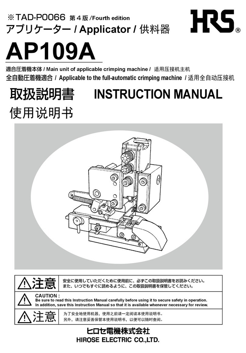
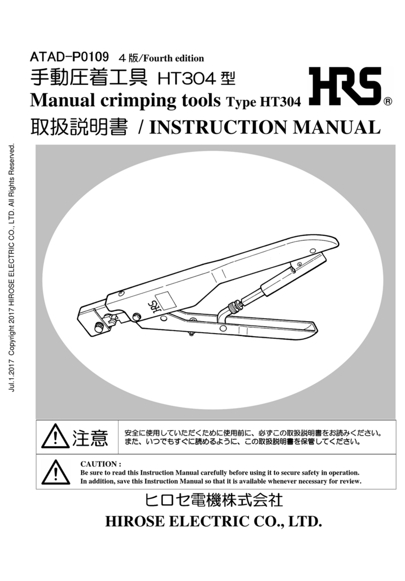
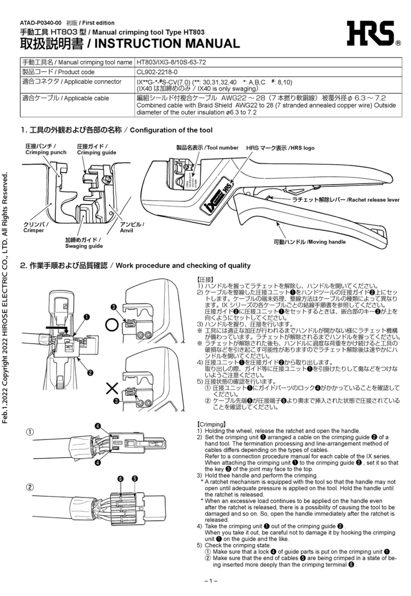
Desk cable connection jig
Model DF19G SERIES
Applicable cable connection jig main units
DF19G-14S/PR-MD2
DF19G-20S/PR-MD2
DF19G-30S/PR-MD2
INSTRUCTION MANUAL
CAUTION :
Be sure to read this Instruction Manual carefully
before using it to secure safety in operation. In
addition, save this Instruction Manual so that it is
available whenever necessary for review.
HIROSE ELECTRIC CO., LTD.
Jan.1.2020Copyright2020HIROSEELECTRICCO.,LTD.AllRightsReserved.

– I –
For safe operation
The operators of the tool and the maintenance personnel who are in charge of maintenance and repair work are required to read
the following SAFETY INSTRUCTIONS so as to avoid injury.
Fully understand the descriptions given in this Instruction Manual and the warning labels attached on the tool, and follow the
instructions.
(I) Description of warning messages
*Determinethedegreeofimpairmentreferringtothebelow-statedclassication.
Major injury : Indicates the loss of eyesight, wounds, burns (hyperthermal and hypothermal burns), electric shocks,
fracture of a bone, poisoning, etc. requiring emergency of extended medical care.
Injury (Minor injury) : Indicates wounds, burns, electric shocks, etc. requiring medical treatment.
Damage to property : Indicates damage to the machinery and or the surrounding area.
Used in the case where it is assumed that misuse of the machine will expose the
operator to immediate danger of major injury or death.
Used in the case where it is assumed that misuse of the machine can expose the
operator to danger of major injury or death.
Used in the case where it is assumed that misuse of the machine can expose the
operator to danger of injury and can cause damage to property.
DANGER
WARNING
CAUTION
SAFETY INSTRUCTIONS
CAUTION
Basic safety instructions
1. Be sure to read this Instruction Manual and all the instructions and other marerialssupplied with the unit as accessories.
Save this Instruction Manual and make it available for review whenever necessary.
2.Topreventpossiblepersonalaccidents,performoperationsothatyourngersorthelikearenotcaughtinthehandle.
In addition, use this machine putting on a place where children's hands cannot reach.
Application and modication
1. To prevent possible personal accidents, this tool shall only be used for its originally intended purpose while following
theinstructionsspeciedinthisInstructionManual.
We assume no responsibility resulting from the use other than the application.
2.Topreventpossiblepersonalaccidents,modicationtothistoolisprohibited.
Weassumenoresponsibilyresultingfromthemodications.
Training
1. To prevent possible accidents caused by unfamiliarity with the operation of the tool, the tool shall only be allowed to
beusedbytheoperatorswhohavebeentrainedforproperoperationandprovidedwithsufcientknowledgeofsafe
operation by the employee.
When operating
1.Topreventpossiblepersonalaccidents,becarefulsothatngersorthelikearenotcaughtinthehandleorthecrimping
section when crimping with this unit.
2. To prevent possible electric shock accidents, turn off the power to the machine or unit and use this crimping machine
when replacing or installing the terminal or contact in a state that the machine or unit is wired.
Maintenance
1. To prevent possible accidents caused by unfamiliarity with the operation of the tool, repair and adjustment of the tool
shall be conducted only by maintenance personnel who have a full knowledge of the tool. Use our genuine parts when
replacing parts. We assume no responsibility for accidents caused by improper repair or adjustment or the use of non-
genuine part(s).
2. To prevent possible personal accidents, be sure to wipe off anticorrosive oil applied to the tool, or oil or water adhered
to the tool during operation before starting operation.
Jan.1.2020Copyright2020HIROSEELECTRICCO.,LTD.AllRightsReserved.

– II –
CONTENTS
I. Specications and conguration ............................................................................... 1
1. Specications ........................................................................................................................................1
2. Applicable product and model ............................................................................................................1
3. Commendable standard of FPC dimensions .....................................................................................1
4. Conguration of desk jig components................................................................................................2
5. Conguration of connector components ............................................................................................2
II. Checking items before operation............................................................................. 3
III. Operating procedure............................................................................................... 4
1. Mounting the ground plate..................................................................................................................4
2. Inserting FPC .......................................................................................................................................4
3. Preliminary insertion of the ground plate..........................................................................................5
4. Setting procedure of the connector.....................................................................................................6
5. Connection work ..................................................................................................................................7
6. Appearance inspection .........................................................................................................................8
7. Electrical test ........................................................................................................................................8
IV. Repairing procedure in case of failure of connection .......................................... 9
V. Precautions in handling the jig............................................................................... 10
VI. Maintenance and inspection ................................................................................. 10
Jan.1.2020Copyright2020HIROSEELECTRICCO.,LTD.AllRightsReserved.

- 1 -
2. Applicable product and model
I. Specications and conguration
1. Specications
Item Specications
Function Desk cable connection jig
Dimensions 230(W) ×117(H)×80(D)
Weight Approx. 3 kg
Applicable product Product number
Connector DF19G-14S-1F DF19G-20S-1F DF19G-30S-1F
Ground plate DF19G-14S-1F-GND DF19G-20S-1F-GND DF19G-30S-1F-GND
Jig DF19G-14S/PR-MD2 DF19G-20S/PR-MD2 DF19G-30S/PR-MD2
3. Commendable standard of FPC dimensions
Dimensions described below denote the standard of FPC dimensions which can be mounted on this jig.
For the detailed dimensions, please contact our engineering division.
B±0.05
2.2 ±0.05
Straight section : more than 7.5 mm
0.245mm
Dimension (mm)
A B
DF19G-14S-1F 15.6 14
DF19G-20S-1F 21.6 20
DF19G-30S-1F 31.6 30
Name of connector
A±0.08
Jan.1.2020Copyright2020HIROSEELECTRICCO.,LTD.AllRightsReserved.

- 2 -
4. Conguration of desk jig components
Shank
Connector lamp
Connector holder
Connector guide
Clamp lever
Base plate
Ratchet
Ratchet release lever
Pressure block
5. Conguration of connector components
Preliminary insertion position
【Ground plate】
Polarization mark
Lock
Preliminary insertion reference
【Connector main body】
DF19G-20S/PR-MD2
9E001
MADE IN JAPAN
HRS No.
Country of origin display
Product name display
Manufacturing No. display
Warning label
Warning label
Connector lamp
Lock punch
Press tting punch
Jan.1.2020Copyright2020HIROSEELECTRICCO.,LTD.AllRightsReserved.

- 3 -
II. Checking items before operation
No.
1
2
3
4
5
6
Checking item
Clamp lever
Ratchet release
Open/close press
ttingpunchand
lock punch
Deformation or
breakage of press
ttingpunchand
lock punch
Setting position
of connector
clamp
Installation state
of components
Checking procedure
• Check whether there is a
clamp feeling when clamp
lever is fully pressed until
it will go no further.
•
Check whether ratchet is
released in the state that
pressure block comes
closely in contact with
base plate face.
•
Check that pressure
block comes closely in
contact with base plate
face and each punch is
smoothly opened without
friction after clamp lever
has been released.
•
Check through eye-ob-
servation whether each
punch has neither defor-
mation nor breakage.
Perform an appearance
inspection with the first
connection product.
•
Check whether con-
nector clamp comes in
contact with set position
when clamp lever is fully
pressed until it will go no
further.
•
Check through eye-ob-
servation whether there
is no lack or breakage of
the respective compo-
nents.
In case of trouble
•
Shut-height is im-
proper and connection
is not correctly per-
formed.
•
Shut-height is im-
proper and connection
is not correctly per-
formed.
•
Shut-height is im-
proper and connection
is not correctly per-
formed when pressure
block does not come
closely in contact with
base plate face.
•
Connection is not cor-
rectly performed when
press fitting punch
or lock punch is de-
formed or broken.
•
Connection is not cor-
rectly performed when
connector lamp does
not come in contact
with set position.
•
Connection is not cor-
rectly performed.
Cause
•
Shank installing
position is improp-
er.
•
Ratchet installing
position is
improp-
er.
•
Deformation of
each punch.
•
Mixture of foreign
materials in slid-
ing parts.
•
Trouble of shut-
height or the like.
•
Mixture of for-
eign materials in
sliding parts.
•
Mixture of for-
eign materials in
clamp or the like.
•
Mixture of foreign
materials in slid-
ing parts.
•
Trouble of shut-
height or the like.
If the jig is defective, do not perform disassembling or the like. Please contact us for repair.
Corrective measure
•
Please request us
for repair.
•
Ditto
•
Ditto
•
Completely remove
foreign materials.
•
Please request us
for repair.
• In case of deforma-
tion or breakage do
not continue to use
the jig. Please re-
quest us for repair.
•
Ditto
•
Ditto
•
Ditto
WARNING :
To prevent personal accidents, extreme caution has to be taken not to allow ngers to be caught in the handle or sliding
parts when crimping with this tool.
Jan.1.2020Copyright2020HIROSEELECTRICCO.,LTD.AllRightsReserved.

- 4 -
III. Operating procedure
1. Mounting the ground plate
1) Face upward signal face ②of FPC ①and polarization
mark ④of the ground plate ③.
2) Mount the ground plate ③so that you do not touch
signal section ②of FPC by hand.
FPC ①
Polarization mark ④
Ground plate ③
FPC ①
Polarization mark side ④
Signal face ②
Ground plate ③
2. Inserting FPC
1) Adjust connector main body ②and polarization mark ④
of the ground plate ③to the same direction.
2) Insert FPC ①until it comes in contact with the inside of
connector main body ②.
FPC ①Connector main body ②
Insertion
Connector main body ②
FPC ①
Cautions when inserting FPC
1.
The connector main body and the ground
plate
will be broken at the time of connec-
tion unless
the connector main body and
the polarization
mark of the ground plate
are set in the same
direction.
2. Insertion may be difcult when FPC is warped.
Ground plate ③
Polarization mark ④
Adjust the direction of FPC referring to
polarization mark " " of the ground plate.
Jan.1.2020Copyright2020HIROSEELECTRICCO.,LTD.AllRightsReserved.
- 5 -
3. Preliminary insertion of the ground plate
1) Making FPC ①come in contact with the inside of
connector main body ②, insert ground plate ③into the
connector main body.
2) Insert the ground plate so that preliminary insertion
position ④comes in front of preliminary insertion
reference ⑤of the connector main body.
Position of preliminary
insertion ④Polarization mark
Preliminary
insertion
Connector main
body
Less than 10 degrees
B:NGA:OK C:NG
● Preliminary insertion quality standard
Checktobesurethatthecomponentthathasbeeninsertedsatisesthefollowingqualitystandards.
A (OK) : Angle when the ground plate is inserted into the connector main body should be less than 10 degrees.
B (NG) : Ground plate is slantingly inserted. Deformation of the ground plate will be caused.
C (NG) : Lower click of the ground plate is widened. rise of the ground plate occurs when setting the connector.
Connector main body ②
Ground plate ③
FPC ①
Cautions when inserting the ground plate
1. Do not use a ground plate which has been excessively warped at the time of preliminary insertion.
2. When the directions of FPC and polarization mark are reverse each other, perform the work from
the rst step without performing the preliminary insertion.
3. After completion of preliminary insertion, do not pull the FPC since the ground plate may come off.
Preliminary insertion
reference ⑤
Jan.1.2020Copyright2020HIROSEELECTRICCO.,LTD.AllRightsReserved.
- 6 -
Connector clamp
Connector set OK
Connector clamp
Connector set NG
Connector clamp ②
Check polarization
mark ①
Connector main body ④
Connector clamp fails to work
Connector clamp
setting position ⑥
Connector holder
Position to make connector main body
come in contact with end face of
connector holder
Connector clamp
Connector
main body guide
width
Connector clamp set position
SET
(Slide to the left-hand side )
OPEN
When the connector clamp is caught on the ground plate and not completely closed even when lightly pressing
itbyngers,itisconsideredthatthepreliminaryinsertionoftheconnectorisnotproperlyperformedduetothe
deformation of the ground plate or the like.
Do not perform the work by force. Return again to the state of the preliminary insertion of the ground plate
(Slide to the right-
hand side )
4. Setting procedure of the connector
1) Face upward polarization mark side ①and slide
connector clamp ②to the right-hand side to open it.
2) Adjust connector main body ④to connector guide face
⑥of connector holder ⑤.
3) Making the connector main body come in contact with
end face of the connector holder, slide connector clamp
⑦to the left-hand side to close it.
When the connector clamp is caught on the
ground plate and not closed by the spring
force alone, lightly press the connector
clamp by ngers up to the set position.
Jan.1.2020Copyright2020HIROSEELECTRICCO.,LTD.AllRightsReserved.

- 7 -
Releasing procedure of the clamp lever
When the ratchet is not released even when the clamp
lever has been fully pressed or you want to temporarily
stop the clamp lever, do not return the clamp lever by
force. Pressing ratchet release lever ①located in the
rear of the tool, release the clamp lever.
(See the enlarged drawing of ratchet section.)
5. Connection work
1) Making connector main body ①come in contact with
the end face of the holder, press FPC ②.
2) Fully press down clamp lever ③until you obtain a
feeling of clamping.
3) Return upward clamp lever ③and release it.
4) Connection work has been completed.
Ratchet release lever ①
Fully press until it
will go no further.
Connector main body ①
FPC ②
Press ①.
(Enlarged drawing of ratchet section )
Please contact us when the connector cannot be taken out even when the clamp lever has been released
or any other trouble has occurred.
Clamp lever ③
WARNING :
Exercise care not to allow hands, ngers or the
like to be caught in any of the moving parts.
SET
Jan.1.2020Copyright2020HIROSEELECTRICCO.,LTD.AllRightsReserved.
- 8 -
6. Appearance inspection
(Inspecting procedure)
Return the clamp lever to its home position and slide the connector clamp by ngers to open it.
Perform the appearance inspection whether the connection is proper after taking out the connector.
1) Lock is performed ①. (See Fig. 1.)
2) There is no defect in the connector main body ②. (See Fig. 2.)
3) There is no rise of ground plate ③. (See Fig. 3.)
4) There is not any other defect such as scratch or the like.
Performtheappearanceinspectionwhetherthequalityissatisedwhentheconnectionworkhasbeencompleted.
Check that lock is
performed ①.
Check that lock is
performed ①.
Connector main body ②Ground plate ③
Rear side
7. Electrical test
Perform the test of Contact resistance, nsulation resistance and withstand voltage.
Fig. 1. Fig. 2. Fig. 3.
Item Test method Standard
Contact resistance Measure at 100 m A
(DC or 1000 Hz) Less than 50 mΩ
Insulation resistance Measue at DC 100 V. More than 500 MΩ
Withstand voltage Apply AC 300 V voltage for
one minute.
No ashover or dielectric
breakdown
Jan.1.2020Copyright2020HIROSEELECTRICCO.,LTD.AllRightsReserved.
- 9 -
IV. Repairing procedure in case of failure of connection
1) Turn over the connector main body which has been failed in connection.
2) Insert pulling tool ④between connector main body ①and lock section (4 places) ③of ground plate ②and
remove the click.
Pulling tool : DF-C-PO (B) (Optional)
3) Press down the ground plate to open it.
4) Press FPC ⑤and ground plate ②byngersandpulloutconnectormainbody①.
5) Remove ground plate ②from the FPC ⑤.
Ground plate ②FPC ⑤
Connector
main body ①
Pulling tool : DF-C-PO (B)
Optional ④
FPC ⑤
Ground plate ②
Pull out
Lock section ③
(4 places right/left)
1. Do not perform re-connection of the connector main body and ground plate for which repair has
been performed. Scrap them.
2. Do not perform more than one time re-connection to FPC for which repair has been performed.
3. Handle the pulling tool with care since the tip of it is very sharp.
Connector
main body ①
Jan.1.2020Copyright2020HIROSEELECTRICCO.,LTD.AllRightsReserved.
- 10 -
V. Precautions in handling the jig
1) Never apply any physical impact to the jig by tapping or dropping from an elevated place.
2) Never crimp any material other than applicable connectors and applicable ground plates given in this Instruction
Manual.
3) When the clamp lever is not released or you want to temporarily stop the clamp lever, never release the lever
since eleasing it by force will be the cause of trouble.
4) If the tool is defective, do not disassemble it but contact us for repair while showing the detailed description of
the defect.
VI. Maintenance and inspection
1) Upon completion of works, wipe the jig to remove stains and foreign materials with a piece of soft cloth and close
the clamp lever to avoid any foreign material from entering the sliding parts. Then, store the jig in a dry place.
2) Check to be sure whether there is a feeling of clamping when the clamp lever has been fully pressed and the
respective sliding parts smoothly slide.
Jan.1.2020Copyright2020HIROSEELECTRICCO.,LTD.AllRightsReserved.
- 11 -
MEMO
Jan.1.2020Copyright2020HIROSEELECTRICCO.,LTD.AllRightsReserved.
– III –
HIROSE ELECTRIC CO., LTD. 2013
(1) No part of this manual may be reproduced without the permission of Hirose Electric Co., Ltd.
(2) Description in this manual is subject to change without notice.
(3) This Instruction Manual has been prepared for clarify. Should you find any unclear portion, error, or
omission, please, for the safety of other, contact our Marketing Department.
(4) It should be understood that, notwithstanding the aforementioned item (3), we assume no liability to any
claim for loss or failure to earn prot resulting from the use of the machine.
(5) We assume no responsibility for any damage resulting from your improper use of the machine including
your failure to follow the instructions given in this Instruction Manual. This includes repair or modication
conducted by any third party other than Hirose Electric Co., Ltd.
(6) Please note that servicing of the machine is not available in any country other than Japan.
CAUTION
Instruction Manual Number
TAD-P6629
Date of issue March 2000
Date of revision December 2013
Edition number Second edition
Jan.1.2020Copyright2020HIROSEELECTRICCO.,LTD.AllRightsReserved.
– V –
13.12 Printed in Japan
HIROSE ELECTRIC CO.,LTD.
5-23, OSAKI 5-CHOME, SHINAGAWA-KU, TOKYO 141-8587, JAPAN
PHONE: 81-03-3491-9741 FAX: 81-03-3493-2933
http://www.hirose.com
Jan.1.2020Copyright2020HIROSEELECTRICCO.,LTD.AllRightsReserved.
This manual suits for next models
3
Table of contents
Other HRS Crimping Tools manuals
Popular Crimping Tools manuals by other brands

Apollo
Apollo PEX 69PTKH00143 instruction sheet

Textron
Textron Klauke EK 60/22-L instruction manual

CIMCO
CIMCO GENiUS 2.0 operating instructions

JST
JST WC Series instruction manual

TE Connectivity
TE Connectivity CERTI- CRIMP Series instruction sheet

Aalberts industries
Aalberts industries Apollo PEX 69PTKH00143 instruction sheet

TE Connectivity
TE Connectivity 607949-1 Original instructions

TE Connectivity
TE Connectivity 2392900-1 manual

Tyco Electronics
Tyco Electronics PRO-CRIMPER III 58603-1 instruction sheet

Emerson
Emerson Klauke EK 135FTCFB manual

TE Connectivity
TE Connectivity SOLISTRAND 1752868-1 instruction sheet

molex
molex 63811-4700 Specification sheet