6BoSS Ladderspan 3T Instruction Manual
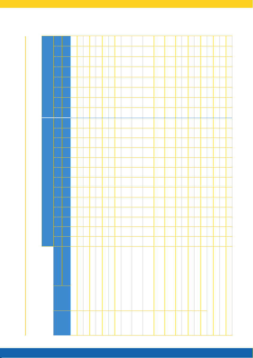
2.3 Quantity Schedule
BoSS 1450 Ladderspan to EN 1004: Available in 2 lengths - 1.8m and 2.5m
Internal or External Use Internal Use
Component
Code Component Working Height (m) 4.2 4.7 5.2 5.7 6.2 6.7 7.2 7.7 8.2 8.7 9.2 9.7 10.2 10.7 11.2 11.7 12.2 12.7 13.2 13.7 14.2
Platform Height (m) 2.2 2.7 3.2 3.7 4.2 4.7 5.2 5.7 6.2 6.7 7.2 7.7 8.2 8.7 9.2 9.7 10.2 10.7 11.2 11.7 12.2
32842300 Castor 150mm 4 4 4 4 4 4 4 4 4 4 4 4 4 4 4 4 4 4 4 4 4
33551300 Adjustable Leg 4 4 4 4 4 4 4 4 4 4 4 4 4 4 4 4 4 4 4 4 4
61151300 Ladder Frame 1450 2 Rung 1 - - 1 1 - - 1 1 - - 1 1 - - 1 1 - - 1 1
60551300 Span Frame 1450 2 Rung 1 - - 1 1 - - 1 1 - - 1 1 - - 1 1 - - 1 1
61051300 Ladder Frame 1450 3 Rung - 1 - 1 - 1 - 1 - 1 - 1 - 1 - 1 - 1 - 1 -
60451300 Span Frame 1450 3 Rung - 1 - 1 - 1 - 1 - 1 - 1 - 1 - 1 - 1 - 1 -
60951300 Ladder Frame 1450 4 Rung 1 1 2 1 2 2 3 2 3 3 4 3 4 4 5 4 5 5 6 5 6
60351300 Span Frame 1450 4 Rung 1 1 2 1 2 2 3 2 3 3 4 3 4 4 5 4 5 5 6 5 6
30151100/
30251100 Fixed Deck 1.8m and 2.5m 1 2 1 1 1 2 1 1 1 2 1 1 1 2 1 1 1 2 1 1 1
30451100/
30551100 Trapdoor Deck 1.8m and 2.5m 1 1 2 2 2 2 3 3 3 3 4 4 4 4 5 5 5 5 6 6 6
31251300/
34851300 Horizontal Brace 1.8m and 2.5m (red) 6 10 10 10 10 14 14 14 14 18 18 18 18 22 22 22 22 26 26 26 26
31351300/
31451300
Diagonal Brace 2.1m and 2.7m
(blue) 4 6 6 8 8 10 10 12 12 14 14 16 16 18 18 20 20 22 22 24 24
30450900/
30550900 Side Toe Board 1.8m and 2.5m 2 2 2 2 2 2 2 2 2 2 2 2 2 2 2 2 2 2 2 2 2
30350900 End Toe Board 1.45m 2 2 2 2 2 2 2 2 2 2 2 2 2 2 2 2 2 2 2 2 2
30150900 Toe Board Holder 4 4 4 4 4 4 4 4 4 4 4 4 4 4 4 4 4 4 4 4 4
31751300 SP7 Fixed Stabiliser 4 4 4 4 4 - - - - - - - - - - - - - - - -
31851300 SP10 Telescopic Stabiliser - - - - - 4 4 4 4 4 4 - - 4 4 4 4 4 4 4 4
31951300 SP15 Telescopic Stabiliser - - - - - - - - - - - 4 4 - - - - - - - -
Tower Total Self-weight 1.8m (kgs) 116 145 149 159 163 211 216 226 230 258 263 288 292 304 309 319 323 351 356 366 369
Tower Total Self-weight 2.5m (kgs) 131 165 170 180 184 239 243 254 257 292 296 323 327 346 350 360 364 399 403 414 418
Max. Exerted Leg Load 1.8m (kgs) 150 150 160 170 180 190 200 210 220 240 255 270 300 300 300 310 310 310 320 320 320
Max. Exerted Leg Load 2.5m (kgs) 170 170 180 180 190 190 200 200 210 260 305 310 320 330 340 350 360 370 380 390 400
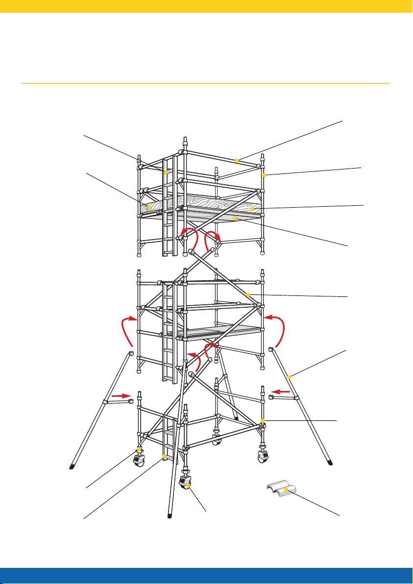
2 Building the Tower