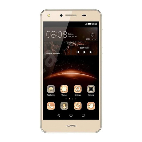
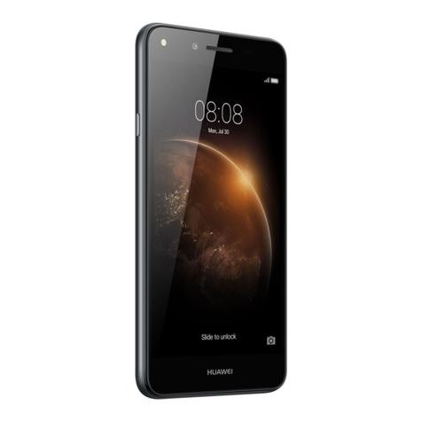
Huawei U8950 Operating manual

HUAWEI
U8950 Maintenance Guide
V1.0
Prepared by
Bi Xiaotao and Zhang Shunzhi
Date
2012.08.15
Reviewed by
Wei Baoquan
Date
2012.08.17
Approved by
Zhao Xianfeng
Date
2012.08.20
Huawei Technologies Co., Ltd.
All rights reserved.

U8950 Maintenance Guide V1.0
INTERNAL
2012-10-22
Huawei Proprietary and Confidential
i
Change History
Date
Version
Change
Reason
Changed
Chapter
Change De
scription
Author
2012.08.15
V1.0
Released the
first version.
Bi Xiaotao
and Zhang
Shunzhi

U8950 Maintenance Guide V1.0
Contents
2012-10-22
Huawei Proprietary and Confidential
ii
Contents
1 Product Overview .........................................................................................................................1
1.1 Appearance.......................................................................................................................................................1
1.2 Features............................................................................................................................................................1
2 Applicable Scope and Precautions ............................................................................................5
2.1 Applicable Scope..............................................................................................................................................5
2.2 Precautions.......................................................................................................................................................5
2.3 How to Obtain Product and Repair Information ..............................................................................................5
3 Exploded View and Components ..............................................................................................6
3.1 Exploded View.................................................................................................................................................6
3.2 Components List ..............................................................................................................................................7
4 Components on the PCBA...........................................................................................................9
5 Software Upgrade .......................................................................................................................13
5.1 Upgrade Preparation.......................................................................................................................................13
5.2 Hardware Connection.....................................................................................................................................13
5.3 Upgrade Using the Phone Driver ...................................................................................................................14
5.3.1 Installing the Phone Driver ...................................................................................................................14
5.3.2 Performing a Normal Upgrade..............................................................................................................17
5.3.3 Performing a Forcible Upgrade.............................................................................................................19
5.4 Troubleshooting Upgrade Failures .................................................................................................................19
6 Maintenance Tools......................................................................................................................21
7 Disassembly Procedure..............................................................................................................23
7.1 Disassembling a Bare Phone..........................................................................................................................23
7.2 Disassembling the Touchscreen .....................................................................................................................25
7.3 Disassembling the LCD .................................................................................................................................27
8 Assembly Procedure...................................................................................................................28
9 Maintenance Records During Verification............................................................................32
9.1 Maintenance Records on Each Stage .............................................................................................................32
10 Principles and Failure Analysis .............................................................................................47
10.1 Baseband Unit..............................................................................................................................................48
U8950 Maintenance Guide V1.0
Contents
2012-10-22
Huawei Proprietary and Confidential
iii
10.1.1 Startup Management Circuits..............................................................................................................48
10.1.2 Charging Management Circuits ..........................................................................................................52
10.1.3 Clock Circuit.......................................................................................................................................59
10.1.4 Flash Memory Circuit.........................................................................................................................61
10.2 RF Unit.........................................................................................................................................................65
10.2.1 Power Amplifier..................................................................................................................................66
10.2.2 Troubleshooting Process .....................................................................................................................67
10.3 Peripheral Circuits........................................................................................................................................70
10.3.1 Display................................................................................................................................................70
10.3.2 Vibration .............................................................................................................................................73
10.3.3 Receiver and Speaker..........................................................................................................................75
10.3.4 Microphone.........................................................................................................................................78
10.3.5 Headset................................................................................................................................................81
10.3.6 SIM Card.............................................................................................................................................83
10.3.7 I/O Connector......................................................................................................................................86
10.3.8 microSD Card Connector....................................................................................................................87
10.3.9 FM and Bluetooth ...............................................................................................................................88
11 Solder Points on the PCB and BGA Chips...........................................................................92
12 Functional Tests.........................................................................................................................96
12.1 Keys .............................................................................................................................................................96
12.2 MMI Test......................................................................................................................................................96
12.3 Voice Call Test..............................................................................................................................................97

U8950 Maintenance Guide V1.0
1 Product Overview
2012-10-22
Huawei Proprietary and Confidential
2
Table 1-1 U8950 product features
Item
Description
Form factor
Bar-type
Display
Size: 4.5 inches
Type: TFT touchscreen
Colors: 16 million colors
Resolution: 960 x 540 pixels
Dimensions
(H x W x D)
134 mm x 67.5 mm x 10.8 mm (5.28 in. x 2.66 in. x 0.43 in.)
Weight
About 150 g (including the battery)
Frequency
bands
U8950D/U8950-1/U8950N-1:
GSM 850 MHz: 824–849 MHz (uplink), 969–894 MHz (downlink)
GSM 900 MHz: 890–915 MHz (uplink), 925–960 MHz (downlink)
GSM 1800 MHz: 1710–1785 MHz (uplink), 1805–1880 MHz
(downlink)
GSM 1900 MHz: 1850–1910 MHz (uplink), 1930–1990 MHz
(downlink)
W-CDMA 900 MHz: 880–915 MHz (uplink), 925–960 MHz (downlink)
W-CDMA 2100 MHz: 1920–1980 MHz (uplink), 2110–2170 MHz
(downlink)
U8950-51/U8950N-51:
GSM 850 MHz: 824–849 MHz (uplink), 969–894 MHz (downlink)
GSM 900 MHz: 890–915 MHz (uplink), 925–960 MHz (downlink)
GSM 1800 MHz: 1710–1785 MHz (uplink), 1805–1880 MHz
(downlink)
GSM 1900 MHz: 1850–1910 MHz (uplink), 1930–1990 MHz
(downlink)
W-CDMA 850 MHz: 824–849 MHz (uplink), 869–894 MHz (downlink)
W-CDMA 1900 MHz: 1850–1910 MHz (uplink), 1930–1960 MHz
(downlink)
W-CDMA 2100 MHz: 1920–1980 MHz (uplink), 2110–2170 MHz
(downlink)
Maximum
transmission
power
GSM/GPRS 850/900 MHz: +33 dBm
GSM/GPRS 1800/1900 MHz: +30 dBm
W-CDMA 850/900/2100 MHz: +24 dBm
W-CDMA 1900 MHz: +23.5 dBm
Static
sensitivity
GSM 850/900/1800/1900 MHz: better than –109 dBm/200 kHz
W-CDMA 850/900/1900/2100 MHz: better than –109 dBm/200 kHz
Data services
HSDPA: 7.2–8 Mbit/s
HSUPA: 5.76–6 Mbit/s

U8950 Maintenance Guide V1.0
1 Product Overview
2012-10-22
Huawei Proprietary and Confidential
3
Item
Description
Ports
Standard micro-USB port, microSD card slot, and 3.5 mm headset jack
Processor
Qualcomm MSM8225, dual-core, 1.2 GHz
Storage space
ROM: 4 GB (Available space: 2 GB)
RAM: 768 MB
Device
control
Touch key feedback, volume keys, power key, charging indicator, gravity
sensor, proximity light sensor, and brightness sensor
Temperature
Operating: –10°C to +40°C
Storage: –10°C to +40°C
Battery
Capacity: 1930 mAh
Standby time (depending on user habits and network conditions): up to
380 hours (2G)/up to 380 hours (3G)
Talk time: up to 400 minutes (2G)/up to 400 minutes (3G)
Charging duration: 3 hours
Operating
humidity
5% to 95% RH
Camera
8.0 MP BSI AF rear camera, 0.3 MP FF front camera
FM radio
Built-in FM radio
Bluetooth
3.0 EDR
WLAN
WLAN, WLAN routing, and C(CDMA)+W(Wi-Fi) function promoted by
China Telecom
USB
USB 2.0
Power supply
100–240 V, 50/60 Hz, 1 A
Certification
Type Approval Certificate, Network Access License, and China
Compulsory Certification
Sensor
Gravity sensor, proximity sensor, and ambient light sensor

U8950 Maintenance Guide V1.0
1 Product Overview
2012-10-22
Huawei Proprietary and Confidential
4
Item
Description
NOTE
AF: autofocus
BSI: backside illumination
EDR: Enhanced Data Rate
FF: fixed focus
FM: frequency modulation
GPRS: general packet radio service
GSM: Global System for Mobile Communications
HSDPA: High-Speed Downlink Packet Access
HSUPA: High-Speed Uplink Packet Access
MP: Megapixel
RAM: random access memory
ROM: read only memory
TFT: thin film transistor
W-CDMA: Wideband Code Division Multiple Access
WLAN: wireless local area network

U8950 Maintenance Guide V1.0
2 Applicable Scope and Precautions
2012-10-22
Huawei Proprietary and Confidential
5
2 Applicable Scope and Precautions
2.1 Applicable Scope
This document provides repair instructions for technicians at service centers authorized by
Huawei. Being Huawei proprietary, this document is accessible only for authorized service
centers and companies. Although every effort was made to ensure the accuracy of this
document, errors may still exist. If you find any errors or have any suggestions, contact
Huawei's customer service.
2.2 Precautions
Only qualified technicians are allowed to perform repair and calibration.
Perform all operations in electrostatic discharge (ESD) rooms and wear ESD wrist straps
throughout the operations.
Ensure that all the components, screws, and insulators are properly installed after repair
and calibration and all cables and wires are installed and connected correctly.
Ensure that the soldering is lead-free and compliant with eco-friendly requirements.
2.3 How to Obtain Product and Repair Information
To obtain product and maintenance information, visit Huawei website at:
http://www.huaweidevice.com/cn/technicaIndex.do
ESD is the main cause of damage to electrostatic-sensitive components. Each ASC must
exercise caution to avoid ESD damage and comply with the ESD protection requirements in
this manual.

U8950 Maintenance Guide V1.0
3 Exploded View and Components
2012-10-22
Huawei Proprietary and Confidential
6
3 Exploded View and Components
3.1 Exploded View
The components listed in Figure 3-1 are structural parts of the phone, and cannot be used as
reference when requesting spare parts.
Figure 3-1 shows the U8650 exploded view.
Figure 3-1 U8650 exploded view

U8950 Maintenance Guide V1.0
3 Exploded View and Components
2012-10-22
Huawei Proprietary and Confidential
7
3.2 Components List
Table 3-1 lists the components of U8650.
Table 3-1 Components of U8650
No.
Description
Quantity
1
LCD protector
1
2
Touchscreen
1
3
Receiver ornament
1
4
LCD
1
5
Front cover assembly
1
6
Receiver
1
7
M1.4 screw
2
8
Receiver FPC
1
9
Main PCBA
1
10
Waterproof label
2
11
Rear camera
1
12
Flash PCBA
1
13
Back cover assembly
1
14
Battery cover assembly
1
15
M1.4 x 3.5 screw
1
16
Battery
1
17
Network Access Flag
1
18
Type label
1
19
Main FPC
1
20
Cable
1
21
Tamper-resistant label
1
22
Speaker
2
23
Front camera support
1
24
Front camera
1
25
Antenna board
1
26
Volume-key FPC
1

U8950 Maintenance Guide V1.0
3 Exploded View and Components
2012-10-22
Huawei Proprietary and Confidential
8
No.
Description
Quantity
NOTE
CMII:
FPC: flexible printed circuit
LCD: liquid crystal display
PCBA: Printed Circuit Board Assembly

U8950 Maintenance Guide V1.0
4 Components on the PCBA
2012-10-22
Huawei Proprietary and Confidential
9
4 Components on the PCBA
Figure 4-1 and Figure 4-2 show the components on the top and bottom sides of the PCBA.
Figure 4-1 Componentson the PCBAtop side
Flash shrapnel
Faults caused if
damaged:Flash fault
U3302, U4202, U3401
RF PAs
Faults caused if
damaged:
RF failure
J1403 SIM card
connectors (dual-
card)
Faults caused if
damaged:
SIM card detection
failure
U2101 RF DCDC
Faults caused if
damaged:
RF PA fault
J902 battery
connector
Faults caused if
damaged:
Startupfailure due to
power outage
J3201 coaxial cable
connector
Faults caused if
damaged:
No or weak RF signals
J1006 board connector
Faults caused if
damaged:
Proximitysensor fault
J1703 headset jack
Faults caused if
damaged:Headset
fault
J1601 TP BTB
connector
Faults caused if
damaged: Touchscreen
fault
J1402 microSDcard
slot
Faults caused if
damaged:
microSDcard detection
failure
C245 button capacitor
Faults caused if
damaged:
System timeinaccurate
after the battery is
swapped
NFCPOGO pin
Faults caused if
damaged:
No NFC function
Rear camera
Faults caused if
damaged:
Camerafault
SIM card connector
Faults caused if
damaged:
Call-makingfailure due to
SIM card detection failure
Bluetooth/Wi-Fi/FM
Faults caused if
damaged:
Bluetooth,Wi-Fi,or FM
failure
U4401NFCchip
(availablefor NFC
version only)
Faults caused if
damaged:
NFC functionfault

U8950 Maintenance Guide V1.0
4 Components on the PCBA
2012-10-22
Huawei Proprietary and Confidential
10
Figure 4-2 Components on the PCBAbottom side
J1101 headset connector
Faults caused if damaged:
No sound can be heard
fromthe headset.
U401 CPU
Faults caused if
damaged:
Loadingor startupfailure
U201 PM chip
Faults caused if
damaged:
Startupfailure due to
short circuit
U1303 LCD backlight
Faults caused if
damaged:
LCD fault
U3101 19.2 MHz clock
Faults caused if
damaged:
Startupfailure
U1700 EMMC
Faults caused if
damaged:
Loadingor startupfailure
J903 main FPC connector
Faults caused if damaged:
No sound can be heard
fromthe speaker and no
vibrationis generated by
the vibrator.
U3501 GSM PA
Faults caused if
damaged:
Startupfailure due to
GSM function fault
U3202 RF switch
Faults caused if
damaged:
RF channel fault
U3801 RTR6285
Faults caused if
damaged:
RF-related faults
J1006 front camera
connector
Faults caused if
damaged:
Front camera error;
garbledimage
U1002
Faults caused if
damaged:
Flash fault or loading
failure
U1402 microSDcard
filter
Faults caused if
damaged:
microSDcard fault or
loading failure
U1204, U1205
Accelerometerand
compass
Faults caused if
damaged:
Compassfault
Table 4-1 is provided for reference only. It is subject to changes without any notices. The
latest component list is available on Huawei's ITEM information system. If you have any
questions, contact your local technical support.
Table 4-1 U8650 BOM list
BOM Code
Description
Location No.
14240229
Angle,SMT,Arc
type,Terminal Dedicated
J1703
14240243
Card Connecter,MicroSD
Receptacle,10pin,1.1mm,Without
Lock,Without Hold Peg,1.0mm,TF
Header height
2.45mm,Terminal Dedicated
J1402
14240271
Card Block Connector,Battery
connector,3pin,Side
Contact,2.5mm,With Plastic
Peg,1.45mm,Mid Mount
J902
39200461
Terminal Baseband Process
U401

U8950 Maintenance Guide V1.0
4 Components on the PCBA
2012-10-22
Huawei Proprietary and Confidential
11
BOM Code
Description
Location No.
IC,WCDMA/GSM Dualmode
BASEBAND PROCESSOR
MSM8225-0-AA,1.2V/1.8V/2.85V,5
76 NSP(Pb free)
39200332
Power Management
IC(PM8029),3.0–4.4V,140WLNSP(p
b-free),Terminal Dedicated
U201
40060391
MCP,4GB(x8)
eMMC,52MHz,1024KB,3.3V/1.8V,
FBGA153,6Gb(x32)
LPDDR1,Terminal Dedicated
U1700
47100551
RF Power Amplifying
Module,880–915MHz,31dB max. at
Pout=28.5dBm,28.5dBm,QFN,Termi
nal Dedicated, APT
U3401
13010262
2140MHz,3.0dB,50V,1411,Terminal
Dedicated
U3702
39200333
Terminal Dedicated
IC,WCMDA/GSM Radio
Transceiver(RTR6285A),2.7V/2.6V/
2.1V,137CSP,Terminal Dedicated
U3801
47090053
RF LNA,1575MHz,14dB min.,1.6dB
max.,SOT886,Terminal Dedicated
U4101
39210010
Terminal Baseband process
IC,Single Band 2.4GHz
WLAN/Bluetooth 2.1/FM Single
chip-BCM4330,2.3–5.5V,WLBGA1
33(Pb-free)
U6011
12020216
Crystal,37.4MHz,10pF/8.3pF/9pF,+/
-10ppm,80ohm,2016,Terminal Dedic
ated
X6201
47100464
RF Power Amplifying
Module,1920MHz–1980MHz,28dB
typ. at
Pout=28dBm,28dBm,QFN,Terminal
Dedicated
U3302
39110733
Switching
Regulators,0.4–3.4V,<3%,2.5A,WL
CSP,SMT,1.75mm x
1.75mm,Terminal Dedicated
U2101
38140069
Semiconductor
Sensor,E-Compass,WLCSP(Pb-free),
3axis,Terminal Dedicated
U1205
38140064
Semiconductor
Sensor,Accelerometer,LGA,3axis,Te
U1204

U8950 Maintenance Guide V1.0
4 Components on the PCBA
2012-10-22
Huawei Proprietary and Confidential
12
BOM Code
Description
Location No.
rminal Dedicated
39110620
Power Driver,1.5A LED flash driver
IC,CSP,Terminal Dedicated
U1002
15060228
MOSFET,P
Channel,-12V,-2.4A,112mohm,-8V,
SOT23,from
15060150,TS16949,Terminal Dedica
ted
Q201
22050053
Microphone, -44dB, D4.0mm*1.3m
m,SMT,Terminal Dedicated
MIC1502
07050089
NTC,47000ohm,0402,1.0*0.5*0.35m
m,Terminal Dedicated
RT501
38020055
Analog Switch,P-channel MOSFET
load
switch-1.2–3.6V-50mohm-WLCSP-
Terminal dedicated
U1231
15040295
Transient
Suppression Diode,6V,25V,3A,9
channel TVS+EMI
filter-CSP,Terminal Dedicated
U1402
12070013
Temperature Compensated Crystal
Oscillator,19.2MHz,+/-0.2ppm,2.8V,
+/-2.0ppm,Terminal Dedicated
U3101
47140032
RF
Switch,824-960MHz/1710--2170MH
z,1.2/2.8,1.6/2.8,30/24,Terminal Ded
icated,TS16949
U3202

U8950 Maintenance Guide V1.0
5 Software Upgrade
2012-10-22
Huawei Proprietary and Confidential
13
5 Software Upgrade
5.1 Upgrade Preparation
Prepare the items listed in Table 5-1
Table 5-1 Items to be prepared before a software upgrade
Category
Item
Description
Upgrade
environment
Computer
Operating system: Windows 2000/Windows
XP
USB cable
BOM code: 02450768
Upgrade tool
NewMultiDownloadU
microSD card
The available space must be greater than 2
GB.
Battery
The power remaining must be more than two
bars.
Upgrade file
NewMultiDownloadU
This version is provided for reference only.
Please download the latest version when
upgrading the phone.
Upgrade
method
USB cable
Normal upgrade
Forcible upgrade
microSD card
Normal upgrade
Forcible upgrade
5.2 Hardware Connection
Connect the hardware in the way described in Figure 5-1.

U8950 Maintenance Guide V1.0
5 Software Upgrade
2012-10-22
Huawei Proprietary and Confidential
14
Figure 5-1 Hardware connection
U8950
USB Cable PC
5.3 Upgrade Using the Phone Driver
5.3.1 Installing the Phone Driver
To install the phone driver on the computer, perform the following steps:
Step 1 Double-click the Handset Windriver.exe file, and click Next in the displayed dialog box to
start the installation.
Step 2 Click I Agree.

U8950 Maintenance Guide V1.0
5 Software Upgrade
2012-10-22
Huawei Proprietary and Confidential
15
Step 3 Click Install.

U8950 Maintenance Guide V1.0
5 Software Upgrade
2012-10-22
Huawei Proprietary and Confidential
16
The installation progress is displayed, as shown in the following figure.
Step 4 After the installation is complete, click Finish.
Other manuals for U8950
1
This manual suits for next models
6
Table of contents
Other Huawei Cell Phone manuals

Huawei
Huawei G7007 User manual

Huawei
Huawei T565 Assembly instructions

Huawei
Huawei Y6Pro User manual

Huawei
Huawei G5000 User manual

Huawei
Huawei P8 Lite 2017 User manual

Huawei
Huawei LYO-L01 User manual

Huawei
Huawei Honor User manual

Huawei
Huawei U9120-6 User manual

Huawei
Huawei T521 User manual

Huawei
Huawei Tap User manual

Huawei
Huawei Mate 8 User manual

Huawei
Huawei M931 User manual

Huawei
Huawei G2802S User manual

Huawei
Huawei P smart Pro User manual

Huawei
Huawei Y6 User manual

Huawei
Huawei Ascend Y210 User manual

Huawei
Huawei CM990 User manual

Huawei
Huawei P40 Pro User manual

Huawei
Huawei Y3 lite-UXX User manual

Huawei
Huawei MTV3.4 User manual