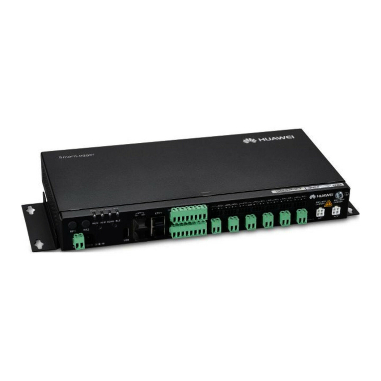
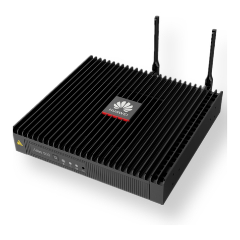
Huawei FusionModule2000 V500R003C10 Operating manual

FusionModule2000 Smart Modular Data Center
V100R022C10
Maintenance Guide
Issue 02
Date 2022-07-30
HUAWEI DIGITAL POWER TECHNOLOGIES CO., LTD.

Copyright © Huawei Digital Power Technologies Co., Ltd. 2022. All rights reserved.
No part of this document may be reproduced or transmitted in any form or by any means without prior
written consent of Huawei Digital Power Technologies Co., Ltd.
Trademarks and Permissions
and other Huawei trademarks are the property of Huawei Technologies Co., Ltd.
All other trademarks and trade names mentioned in this document are the property of their respective
holders.
Notice
The purchased products, services and features are stipulated by the contract made between Huawei
Digital Power Technologies Co., Ltd. and the customer. All or part of the products, services and features
described in this document may not be within the purchase scope or the usage scope. Unless otherwise
specied in the contract, all statements, information, and recommendations in this document are
provided "AS IS" without warranties, guarantees or representations of any kind, either express or implied.
The information in this document is subject to change without notice. Every eort has been made in the
preparation of this document to ensure accuracy of the contents, but all statements, information, and
recommendations in this document do not constitute a warranty of any kind, express or implied.
Huawei Digital Power Technologies Co., Ltd.
Address: Huawei Digital Power Antuoshan Headquarters
Futian,Shenzhen 518043
People's Republic of China
Website: https://e.huawei.com
Issue 02 (2022-07-30) Copyright © Huawei Digital Power Technologies Co., Ltd. i

About This Document
Purpose
This document describes FusionModule2000 smart modular data center
(FusionModule2000 for short) in terms of routine maintenance, troubleshooting,
and parts replacement. It aids regular verication, maintenance and prompt
solutions for device potential faults.
Intended Audience
This document is intended for:
● Technical support engineers
● Commissioning engineers
● Data conguration engineers
● Maintenance engineers
● Electrical engineers
Symbol Conventions
The symbols that may be found in this document are dened as follows.
Symbol Description
Indicates a hazard with a high level of risk which, if not
avoided, will result in death or serious injury.
Indicates a hazard with a medium level of risk which, if not
avoided, could result in death or serious injury.
Indicates a hazard with a low level of risk which, if not
avoided, could result in minor or moderate injury.
Indicates a potentially hazardous situation which, if not
avoided, could result in equipment damage, data loss,
performance deterioration, or unanticipated results.
NOTICE is used to address practices not related to personal
injury.
FusionModule2000 Smart Modular Data Center
Maintenance Guide About This Document
Issue 02 (2022-07-30) Copyright © Huawei Digital Power Technologies Co., Ltd. ii

Symbol Description
Supplements the important information in the main text.
NOTE is used to address information not related to
personal injury, equipment damage, and environment
deterioration.
Change History
Issue Date Description
02 2022-07-30 ● Updated the safety
information.
● Updated the tool list.
01 2022-04-30 This issue is the rst
ocial release.
FusionModule2000 Smart Modular Data Center
Maintenance Guide About This Document
Issue 02 (2022-07-30) Copyright © Huawei Digital Power Technologies Co., Ltd. iii

Contents
About This Document................................................................................................................ ii
1 Safety Information.................................................................................................................. 1
1.1 Personal Safety.........................................................................................................................................................................2
1.2 Electrical Safety........................................................................................................................................................................3
1.3 Environmental Requirements.............................................................................................................................................. 5
1.4 Mechanical Safety................................................................................................................................................................... 7
1.5 UPS Safety............................................................................................................................................................................... 11
1.6 Cooling System Safety.........................................................................................................................................................12
1.7 Battery Safety......................................................................................................................................................................... 13
2 O&M Preparations.................................................................................................................19
2.1 O&M Personnel Skill Requirements................................................................................................................................19
2.2 Tools.......................................................................................................................................................................................... 20
2.3 Reference Documentation................................................................................................................................................. 22
3 Routine Maintenance........................................................................................................... 24
3.1 Overview.................................................................................................................................................................................. 24
3.2 Routine Maintenance.......................................................................................................................................................... 25
3.3 Monthly Maintenance......................................................................................................................................................... 27
3.4 Quarterly Maintenance....................................................................................................................................................... 32
3.5 Semiannual Maintenance.................................................................................................................................................. 41
3.6 Annual Maintenance........................................................................................................................................................... 52
4 Alarms and Troubleshooting.............................................................................................. 54
4.1 Alarm Handling Flowchart................................................................................................................................................ 55
4.2 Viewing and Collecting Alarm Information................................................................................................................. 55
4.3 Determining the Faulty Area and Alarm Severity..................................................................................................... 56
4.4 Locating and Rectifying Faults......................................................................................................................................... 56
5 Parts Replacement................................................................................................................ 58
5.1 CommonECC800-Pro Operations.................................................................................................................................... 58
5.1.1 Preparations and WebUI Login..................................................................................................................................... 58
5.1.2 Synchronizing the Conguration Parameters.......................................................................................................... 62
5.2 Replacing Power Supply and Distribution System Components.......................................................................... 62
5.2.1 Parts Replacement for the Precision PDF..................................................................................................................62
FusionModule2000 Smart Modular Data Center
Maintenance Guide Contents
Issue 02 (2022-07-30) Copyright © Huawei Digital Power Technologies Co., Ltd. iv

5.2.2 Parts Replacement for the Integrated PDF...............................................................................................................62
5.2.3 Parts Replacement for the Integrated UPS...............................................................................................................63
5.2.4 Replacing an rPDU............................................................................................................................................................ 63
5.2.5 Replacing a Smart rPDU................................................................................................................................................. 64
5.2.6 Parts Replacement for Smart Busbars........................................................................................................................65
5.3 Parts Replacement for the Cooling System................................................................................................................. 66
5.3.1 Parts Replacement for Smart Cooling Products......................................................................................................66
5.4 Parts Replacement for the Management System......................................................................................................67
5.4.1 Parts Replacement for the ECC800-Pro..................................................................................................................... 67
5.4.1.1 Replacing an ECC800-Pro Main Control Module................................................................................................ 67
5.4.1.2 Replacing an ECC800-Pro PSU...................................................................................................................................69
5.4.1.3 Replacing ECC800-Pro Antennas.............................................................................................................................. 69
5.4.1.4 Replacing a SIM Card and Micro SD Card............................................................................................................. 70
5.4.2 Replacing the Management System........................................................................................................................... 71
5.4.2.1 Replacing an IVS1800................................................................................................................................................... 71
5.4.2.2 Replacing a Hard Disk for the IVS1800.................................................................................................................. 73
5.4.2.3 Replacing a Camera...................................................................................................................................................... 75
5.4.3 Parts Replacement for the Access System................................................................................................................ 76
5.4.3.1 Replacing an Access Actuator....................................................................................................................................76
5.4.3.2 Replacing an Access Control Device........................................................................................................................ 77
5.4.3.3 Replacing a Button........................................................................................................................................................ 78
5.4.3.4 Replacing a Sliding Door Magnetic Lock............................................................................................................... 79
5.4.3.5 Replacing a Double-Door Magnetic Lock..............................................................................................................81
5.4.3.6 Replacing a Door Status Sensor................................................................................................................................86
5.4.3.7 Replacing a Cabinet Electronic Lock........................................................................................................................87
5.4.3.8 Replacing a Cabinet Fingerprint and Card Lock..................................................................................................88
5.4.3.9 Replacing an Automatic Door Status Sensor....................................................................................................... 89
5.4.4 Replacing a Smart ETH Gateway................................................................................................................................. 90
5.4.5 Replacing the WiFi Module............................................................................................................................................ 91
5.4.6 Replacing a Multi-Functional Sensor..........................................................................................................................91
5.4.7 Replacing a Smoke Detector......................................................................................................................................... 92
5.4.8 Replacing a Cabinet Temperature Sensor................................................................................................................. 93
5.4.9 Replacing a Temperature and Humidity Sensor..................................................................................................... 94
5.4.10 Replacing an Ambient T/H Sensor (33010516)....................................................................................................97
5.4.11 Replacing a Water Sensor..........................................................................................................................................100
5.4.12 Replacing an Alarm Beacon...................................................................................................................................... 102
5.4.13 Replacing a UIM20A expansion module.............................................................................................................. 103
5.4.14 Replacing a FusionModule Actuator......................................................................................................................104
5.4.15 Replacing the Fuse for a FusionModule Actuator.............................................................................................106
5.4.16 Replacing a Skylight Magnetic Lock...................................................................................................................... 106
5.4.17 Replacing a Pad.............................................................................................................................................................107
5.4.18 Replacing the Smart Screen...................................................................................................................................... 108
FusionModule2000 Smart Modular Data Center
Maintenance Guide Contents
Issue 02 (2022-07-30) Copyright © Huawei Digital Power Technologies Co., Ltd. v

5.4.19 Replacing a PAD Power Connector.........................................................................................................................109
5.4.20 Replacing an Aisle LED Light.................................................................................................................................... 114
5.4.21 Replacing the Strip Light of an Atmosphere Light........................................................................................... 116
5.4.22 Replacing an Atmosphere Light Power Supply.................................................................................................. 116
5.4.23 Replacing an eLight Strip Light................................................................................................................................118
5.4.24 Replacing an eLight Actuator................................................................................................................................... 119
5.4.25 Replacing an eLight Power Supply......................................................................................................................... 121
5.4.26 Replacing Cables on the Guide Rail of an Electric Sliding Door.................................................................. 123
5.4.27 Replacing a Smart U Space Manager (Connected to a UIM20A Expansion Module) (BOM Number:
52273314).................................................................................................................................................................................... 124
5.4.28 Replacing a Smart U Space Manager (Connected to a UIM20A Expansion Module) (BOM Number:
52275819).................................................................................................................................................................................... 127
5.5 Common Maintenance Tasks......................................................................................................................................... 128
5.5.1 Operating a Hydraulic Circuit breaker (Inside the Smart rPDU)....................................................................128
5.5.2 Handling Long-time Hotspot at the Air Inlet of a Cabinet in iCooling Mode........................................... 129
A Acronyms and Abbreviations........................................................................................... 131
FusionModule2000 Smart Modular Data Center
Maintenance Guide Contents
Issue 02 (2022-07-30) Copyright © Huawei Digital Power Technologies Co., Ltd. vi

1 Safety Information
Statement
Before installing, operating, and maintaining the equipment, read this document
and observe all the safety instructions on the equipment and in this document.
The "NOTICE", "CAUTION", "WARNING", and "DANGER" statements in this
document do not cover all the safety instructions. They are only supplements to
the safety instructions. The Company will not be liable for any consequence
caused by the violation of general safety requirements or design, production, and
usage safety standards.
Ensure that the equipment is used in environments that meet its design
specications. Otherwise, the equipment may become faulty, and the resulting
equipment malfunction, component damage, personal injuries, or property
damage will not be covered under the warranty.
Follow local laws and regulations when installing, operating, or maintaining the
equipment. The safety instructions in this document are only supplements to local
laws and regulations.
The Company will not be liable for any consequences of the following
circumstances:
● Operation beyond the conditions specied in this document
● Installation or use in environments which are not specied in relevant
international or national standards
● Unauthorized modications to the product or software code or removal of the
product
● Failure to follow the operation instructions and safety precautions on the
product and in this document
● Equipment damage due to force majeure, such as earthquakes, re, and
storms
● Damage caused during transportation by the customer
● Storage conditions that do not meet the requirements specied in this
document
FusionModule2000 Smart Modular Data Center
Maintenance Guide 1 Safety Information
Issue 02 (2022-07-30) Copyright © Huawei Digital Power Technologies Co., Ltd. 1

1.1 Personal Safety
D ANGER
Do not work with power on during installation. Do not install or remove a power
cable with power on. Transient contact between the core of the power cable and
the conductor will generate electric arcs or sparks, which may cause a re or
personal injury.
D ANGER
Before installing, operating, or maintaining the equipment, remove conductive
objects such as watches, bracelets, bangles, rings, and necklaces to prevent electric
shocks.
D ANGER
When installing, operating, or maintaining the equipment, use dedicated insulated
tools to prevent electric shocks and short circuits.
WARNING
When installing, operating, or maintaining the equipment, wear personal
protective equipment (PPE) such as insulated gloves, safety clothing, goggles,
safety helmet, and safety shoes.
General Requirements
● Do not stop protective devices. Pay attention to the warnings, cautions, and
precautionary measures on the equipment.
● If there is a likelihood of personal injury or equipment damage during
operations, immediately stop, report the case to the supervisor, and take
feasible protective measures.
● Do not power on the equipment before it is installed or conrmed by
professionals.
● Before handling a conductor surface or terminal, measure the contact point
voltage and ensure that there is no risk of electric shock.
● Do not touch a running fan with your ngers, components, screws, tools, or
boards before the fan is powered o or stops running.
● In the case of a re, immediately leave the building or the equipment area
and activate the re alarm or call emergency services. Do not re-enter the
building or aected area until it has been deemed safe by qualied
professionals.
FusionModule2000 Smart Modular Data Center
Maintenance Guide 1 Safety Information
Issue 02 (2022-07-30) Copyright © Huawei Digital Power Technologies Co., Ltd. 2

Personnel Requirements
● Only professionals and trained personnel are allowed to operate the
equipment.
– Professionals: personnel who are familiar with the working principles and
structure of the equipment, trained or experienced in equipment
operations and are clear of the sources and degree of various potential
hazards in equipment installation, operation, maintenance
– Trained personnel: personnel who are trained in technology and safety,
have required experience, are aware of possible hazards on themselves in
certain operations, and are able to take protective measures to minimize
the hazards on themselves and other people
● Personnel who plan to install or maintain the equipment must receive
thorough training, understand all necessary safety precautions, and be able to
correctly perform all operations.
● Only qualied professionals or trained personnel are allowed to install,
operate, and maintain the equipment.
● Only qualied professionals are allowed to remove safety facilities and inspect
the equipment.
● Personnel who will perform special tasks such as electrical operations,
working at heights, and operations of special equipment should possess the
required local national qualications.
● Only authorized professionals are allowed to replace the equipment or
components (including software).
● Keep irrelevant people away from the equipment. Only operators are allowed
to access the equipment.
1.2 Electrical Safety
General Requirements
● Installation, operation, and maintenance must be performed in the sequence
specied in the manual. Do not change the structure or installation sequence
of the equipment without permission.
● When installing the equipment, use a torque wrench with a proper range to
tighten the screws. When using a wrench to tighten the screws, ensure that
the wrench does not tilt and the torque error does not exceed 10% of the
specied value.
● Before installing or removing power cables, ensure that the switch is turned
o.
● If the equipment has multiple inputs, disconnect all the inputs before
operating the equipment.
● Before connecting power cables, check that cable labels are correct and cable
terminals are insulated.
● A circuit breaker equipped with a residual current device (RCD) is not
recommended.
● It is recommended that the three-phase loads be equalized and the neutral-
ground voltage be kept at less than 2 V to meet power distribution
requirements.
FusionModule2000 Smart Modular Data Center
Maintenance Guide 1 Safety Information
Issue 02 (2022-07-30) Copyright © Huawei Digital Power Technologies Co., Ltd. 3

● To avoid electric shock, do not connect safety extra-low voltage (SELV) circuits
to telecommunication network voltage (TNV) circuits.
● A damaged cable must be replaced by the manufacturer or professionals to
avoid risks.
● Check equipment connections periodically, ensuring that all screws are
securely tightened.
● Do not use water to clean electrical components inside or outside of a
cabinet.
● Do not scrawl, damage, or block any labels or nameplates on the equipment.
Promptly replace warning labels that have worn out.
Grounding
● For the equipment that needs to be grounded, install the ground cable rst
when installing the equipment and remove the ground cable last when
removing the equipment.
● Ensure that the equipment is connected permanently to the protective
ground. Before operating the equipment, check its electrical connection to
ensure that it is reliably grounded.
● If a "high electricity leakage" tag is attached on the equipment, ground the
protective ground terminal on the equipment enclosure before connecting the
AC input power supply; otherwise, electric shock as a result of electricity
leakage may occur.
● Do not operate the equipment in the absence of a properly installed ground
conductor.
● Do not damage the ground conductor.
Cabling
● When selecting, connecting, and routing cables, follow local safety regulations
and rules.
● The ame spread rating of cables should meet the UL 1581 VW-1 or IEC
60332-3-22 (ZB) or higher requirements.
● Do not route cables behind the air intake or exhaust vents of the equipment.
● If a cable is connected to the cabinet from the top, bend the cable in a U
shape outside the cabinet and then route it into the cabinet.
● Bind cables of the same type together. When routing cables of dierent types,
ensure that they are at least 30 mm away from each other.
● When routing cables, ensure that a distance of at least 30 mm exists between
the cables and heat-generating components or areas. This prevents damage
to the insulation layer of the cables.
● When the temperature is low, violent impact or vibration may damage the
plastic cable sheathing. To ensure safety, comply with the following
requirements:
– Cables can be laid or installed only when the temperature is higher than
0°C. Handle cables with caution, especially at a low temperature.
– Cables stored at subzero temperatures must be stored at room
temperature for at least 24 hours before they are laid out.
FusionModule2000 Smart Modular Data Center
Maintenance Guide 1 Safety Information
Issue 02 (2022-07-30) Copyright © Huawei Digital Power Technologies Co., Ltd. 4

● Do not perform any improper operations, for example, dropping cables
directly from a vehicle. Otherwise, the cable performance may deteriorate due
to cable damage, which aects the current-carrying capacity and temperature
rise.
ESD
NO TICE
The static electricity generated by human bodies may damage the electrostatic-
sensitive components on boards, for example, the large-scale integrated (LSI)
circuits.
● Wear ESD gloves or a well-grounded ESD wrist strap when touching the
device or handling boards or application-specic integrated circuits (ASICs).
● When holding a board, hold its edge without touching any components. Do
not touch the components with your bare hands.
● Package boards with ESD packaging materials before storing or transporting
them.
Figure 1-1 Wearing an ESD wrist strap
1.3 Environmental Requirements
WARNING
Install the equipment in an area far away from liquids. Do not install it under
areas prone to condensation, such as under water pipes and air exhaust vents, or
areas prone to water leakage, such as air conditioner vents, ventilation vents, or
feeder windows of the equipment room. Ensure that no liquid enters the
equipment to prevent faults or short circuits.
FusionModule2000 Smart Modular Data Center
Maintenance Guide 1 Safety Information
Issue 02 (2022-07-30) Copyright © Huawei Digital Power Technologies Co., Ltd. 5

General Requirements
● Do not install or run the equipment beyond the technical specications.
Otherwise, its performance and safety will be compromised.
● Do not install the equipment in environments with conductive metal scraps in
the air.
● Do not install the equipment in an environment with direct sunlight, dust,
volatile gases, infrared and other radiations, organic solvents, corrosive
materials, or salty air.
● Do not expose the equipment to ammable or explosive gas or smoke. Do
not perform any operation on the equipment in such environments.
● Do not install, use, or operate outdoor equipment and cables (including but
not limited to moving equipment, operating equipment and cables, inserting
connectors to or removing connectors from signal ports connected to outdoor
facilities, working at heights, and performing outdoor installation) in harsh
weather conditions such as lightning, rain, snow, and level 6 or stronger wind.
● If any liquid is detected inside the equipment, disconnect the power supply
immediately and contact the administrator.
● To prevent re due to high temperature, ensure that the ventilation vents or
heat dissipation system are not blocked when the equipment is running.
● The equipment room should have good heat insulation, and the walls and
oor should be protected against moisture.
● Install a rat guard at the door of the equipment room.
● All cable holes should be sealed. Seal the used cable holes with sealing putty.
Seal the unused cable holes with the caps delivered with the cabinet. The
following gure shows the criteria for correct sealing with sealing putty.
● After installing the equipment, remove idle packing materials such as cartons,
foam, plastics, and cable ties from the equipment area.
Working at Heights
● Working at heights refers to operations that are performed at least 2 meters
above the ground.
● Do not work at heights if the steel pipes are wet or other potential danger
exists. After the preceding conditions no longer exist, the safety director and
relevant technical personnel need to check the involved equipment. Operators
can begin working only after obtaining consent.
FusionModule2000 Smart Modular Data Center
Maintenance Guide 1 Safety Information
Issue 02 (2022-07-30) Copyright © Huawei Digital Power Technologies Co., Ltd. 6

● When working at heights, comply with local relevant laws and regulations.
● Only trained and qualied personnel are allowed to work at heights.
● Before working at heights, check the climbing tools and safety gears such as
safety helmets, safety belts, ladders, springboards, scaolding, and lifting
equipment. If they do not meet the requirements, take corrective measures or
disallow working at heights.
● Wear personal protective equipment such as the safety helmet and safety belt
or waist rope and fasten it to a solid structure. Do not mount it on an
insecure moveable object or metal object with sharp edges. Make sure that
the hooks will not slide o.
● Set a restricted area and prominent signs for working at heights to warn away
irrelevant personnel.
● Carry the operation machinery and tools properly to prevent them from
falling o and causing injuries.
● Personnel involving working at heights are not allowed to throw objects from
the height to the ground, or vice versa. Objects should be transported by
tough slings, hanging baskets, highline trolleys, or cranes.
● Ensure that guard rails and warning signs are set at the edges and openings
of the area involving working at heights to prevent falls.
● Do not pile up scaolding, springboards, or other sundries on the ground
under the area involving working at heights. Do not allow people to stay or
pass under the area involving working at heights.
● Inspect the scaolding, springboards, and workbenches used for working at
heights in advance to ensure that their structures are solid and not
overloaded.
● Any violations must be promptly pointed out by the site manager or safety
supervisor and the involved personnel must correct their operations. Personnel
who fail to comply with the requirements must stop the operations.
1.4 Mechanical Safety
WARNING
When pulling equipment out of a cabinet, be aware of unstable or heavy objects
in the cabinet to prevent injury.
General Requirements
● Repaint any paint scratches caused during equipment transportation or
installation in a timely manner. Equipment with scratches cannot be exposed
to an outdoor environment for an extended period of time.
● Before installation, ensure that the equipment is rmly anchored to the oor
or other solid objects, such as a wall or an installation rack.
Hoisting
● Do not walk under hoisted objects.
FusionModule2000 Smart Modular Data Center
Maintenance Guide 1 Safety Information
Issue 02 (2022-07-30) Copyright © Huawei Digital Power Technologies Co., Ltd. 7

● Only trained and qualied personnel should perform hoisting operations.
● Check that hoisting tools are available and in good condition.
● Before hoisting objects, ensure that hoisting tools are rmly secured onto a
load-bearing object or wall.
● Ensure that the angle formed by two hoisting cables is no more than 90
degrees, as shown in the following gure.
● Do not drag steel ropes and hoisting tools or bump hoisted objects against
hard objects during hoisting.
Moving Heavy Objects
● Be cautious to avoid injury when moving heavy objects.
● When moving the equipment by hand, wear protective gloves to prevent
injuries.
● Move or lift the equipment by holding its handles or lower edges. Do not hold
the handles of modules (such as power supply units, fans, and boards) that
are installed in the equipment because they cannot support the weight of the
equipment.
● Avoid scratching the cabinet surface or damaging cabinet components and
cables during equipment transportation.
● When transporting the equipment using a forklift truck, ensure that the forks
are properly positioned so that the equipment does not topple. Before moving
FusionModule2000 Smart Modular Data Center
Maintenance Guide 1 Safety Information
Issue 02 (2022-07-30) Copyright © Huawei Digital Power Technologies Co., Ltd. 8

the equipment, secure it to the forklift truck using ropes. When moving the
equipment, assign dedicated personnel to take care of it.
● Choose a road with good conditions or sea for transportation to ensure
equipment safety. Avoid tilt or jolt during transportation.
● Move a cabinet with caution. Any bumping or falling may damage the
equipment.
Figure 1-2 Requirements on the cabinet tilt angle
Using Ladders
● Use wooden or berglass ladders when you need to perform live working at
heights.
● When a step ladder is used, ensure that the pull ropes are secured and the
ladder is held rm.
● Before using a ladder, check that it is intact and conrm its load bearing
capacity. Do not overload it.
● Ensure that the ladder is securely positioned. The recommended angle for a
ladder against the oor is 75 degrees, as shown in the following gure. An
angle ruler can be used to measure the angle. Ensure that the wider end of
the ladder is at the bottom, or protective measures have been taken at the
bottom to prevent the ladder from sliding.
FusionModule2000 Smart Modular Data Center
Maintenance Guide 1 Safety Information
Issue 02 (2022-07-30) Copyright © Huawei Digital Power Technologies Co., Ltd. 9

● When climbing a ladder, take the following precautions to reduce risks and
ensure safety:
– Keep your body steady.
– Do not climb higher than the fourth rung of the ladder from the top.
– Ensure that your body's center of gravity does not shift outside the legs
of the ladder.
Drilling Holes
WARNING
Do not drill holes into the equipment. Doing so may aect the electromagnetic
shielding of the equipment and damage components or cables inside. Metal
shavings from drilling may short-circuit boards inside the equipment.
● Obtain consent from the customer and contractor before drilling holes.
● Wear goggles and protective gloves when drilling holes.
● When drilling holes, protect the equipment from shavings. After drilling, clean
up any shavings that have accumulated inside or outside the equipment.
Welding Safety
● At least two persons are required onsite.
● A welder must have a work permit.
● A welding site must be free from inammables.
● Ensure that a re extinguisher, wet cloth, and water container are available.
● A burning welding torch must not be placed on a component or on the oor,
and must not be placed in a metal container with acetylene and oxygen.
Otherwise, the gas may leak and cause a re.
● High-temperature pipes after welding must be promptly cooled.
● Do not weld or cut on pressurized containers or pipes. Electric devices must be
powered o before welding.
FusionModule2000 Smart Modular Data Center
Maintenance Guide 1 Safety Information
Issue 02 (2022-07-30) Copyright © Huawei Digital Power Technologies Co., Ltd. 10

1.5 UPS Safety
D ANGER
During installation, operation, and maintenance, prevent foreign matter from
entering the UPS. Otherwise, equipment damage, load power derating, power
failure, or personal injury may occur.
NO TICE
The category 2 (C2) UPS may cause radio interference when used in a residential
environment. Additional measures may be needed to prevent the interference.
NO TICE
The category 3 (C3) UPS is intended for commercial and industrial application in
the second class environment. Installation restrictions or additional measures may
be needed to prevent disturbances.
General Requirements
● The UPS is used for commercial and industrial purposes only. It cannot be
used as a power supply for life support devices.
● For power supply systems that are critical to signicant economic interests or
public order, such as the national computing center, military command
system, emergency command center, railway signal system and control center,
civil aviation and air trac control center, airport command center, nancial
clearing center, and transaction center, the Tier 4 or 3 power architecture
specied in TIA-942 must be used. That is, two power supplies must be used
to supply power to loads.
● If the root mean square (RMS) of the mains voltage exceeds 320 V AC, the
UPS may be damaged.
● A UPS can be used to serve resistive-capacitive loads, resistive loads, and
micro-inductive loads. It is recommended that a UPS not be used for pure
capacitive loads, pure inductive loads, and half-wave rectication loads. A UPS
does not apply to regeneration loads.
● The UPS can be congured with a backfeed protection dry contact to work
with an external automatic circuit breaker, preventing the voltage from
owing back to input terminals over static bypass circuits. If the installation
and maintenance personnel do not need backfeed protection, paste labels on
external mains and bypass input switches, informing that the UPS is
connected to a backfeed protection card. Disconnect the backfeed protection
card from the UPS before operating the UPS.
● The upstream power distribution of the UPS should comply with IEC
60364-4-41.
FusionModule2000 Smart Modular Data Center
Maintenance Guide 1 Safety Information
Issue 02 (2022-07-30) Copyright © Huawei Digital Power Technologies Co., Ltd. 11

Environmental Requirements
● The UPS operating environment must meet the requirements for the climate
indicator, mechanically active substance indicator, and chemically active
substance indicator in ETSI EN 300 019-1 class 3.6.
● Ensure that the equipment is used in an environment that meets the product
design specications (including power grid, temperature, and humidity).
Otherwise, the equipment may become faulty, and the resulting equipment
malfunction and component damage are not covered under the warranty.
● After unpacking the UPS, you are advised to power it on as soon as possible.
If the UPS is not in operation, take appropriate measures to prevent moisture,
dust, and foreign matter from entering the UPS.
● Any operation on any electrical equipment in an environment that has
inammable air can cause extreme danger. Strictly obey the operating
environmental requirements specied in related user manuals when using or
storing the equipment.
● Do not use the UPS in the following places:
– Environments that are close to ammable or explosive materials, dust,
corrosive gases or dust, conductive or magnetic dust, abnormal vibration,
or collision
– Rooms or outdoor environments where temperature and humidity are
not controlled (with high temperature, low temperature, moisture, direct
sunlight, or heat sources)
–Non-conned environments near the ocean (0–3.7 km) and indoor or
semi-indoor environments where the temperature and humidity are not
controllable, such as simple equipment rooms, civil houses, garages,
corridors, and direct ventilation cabinets near the ocean; or houses with
only roofs, railway station platforms, gymnasiums, and aquariums
– Environments that are conducive for the growth of microorganisms such
as fungus or mildew
– Environments where rodents (such as mice) and insects exist
1.6 Cooling System Safety
High Temperature and Pressure
● When maintaining or replacing components, pay attention to high-
temperature components (such as the compressor, refrigerant pipe, and
electric heater) to prevent scalds.
● When maintaining or replacing components, pay attention to high-pressure
components (such as the compressor and refrigerant pipe) to prevent the
refrigerant system from being cracked or exploded due to misoperations.
Refrigerant Frostbite
Refrigerant leakage may cause frostbite. Take protective measures (for example,
wear antifreeze gloves) when handling refrigerant.
FusionModule2000 Smart Modular Data Center
Maintenance Guide 1 Safety Information
Issue 02 (2022-07-30) Copyright © Huawei Digital Power Technologies Co., Ltd. 12

Storage and Recycling
● Do not store devices near a heat source or under direct sunshine.
● Keep devices away from re or high-temperature objects, especially devices
injected with pressurized nitrogen or refrigerant; otherwise, explosion or
refrigerant leakage may occur, causing personal injury.
● The sign indicates that the product cannot be disposed of with other
wastes that have a shell in European Union (EU) areas. To avoid environment
pollution and harm to human health, wastes must be classied and recycled.
This also promotes resource reuse. When recycling a device, ll in the device
information in the recycling collection system or contact your dealer for help.
The dealer can help you recycle devices in a safe and environment-friendly
way.
1.7 Battery Safety
Before installing, operating, or maintaining batteries, read the battery
manufacturer's instructions. Observe the safety precautions provided in this
document which are supplemental to the safety instructions provided by the
battery manufacturer.
D ANGER
Do not short-circuit the positive and negative poles of batteries. Battery short
circuits can generate high instantaneous current, which may cause battery
leakage, overheating, re, or explosion. To avoid battery short circuit, do not
maintain batteries with power on.
D ANGER
Do not expose batteries at high temperatures or around heat-generating sources,
such as high-temperature sunlight, res, transformers, and heaters. Battery
overheating caused by external heat sources may cause vent opening, leakage,
re, or explosions.
D ANGER
Protect batteries from mechanical vibration, collision, punctures, and strong
impact. Otherwise, the batteries may catch re.
FusionModule2000 Smart Modular Data Center
Maintenance Guide 1 Safety Information
Issue 02 (2022-07-30) Copyright © Huawei Digital Power Technologies Co., Ltd. 13
Other manuals for FusionModule2000 V500R003C10
7
This manual suits for next models
1
Table of contents
Other Huawei Data Logger manuals

Huawei
Huawei FusionModule 1000A20 User manual

Huawei
Huawei FusionModule 1000B Operating manual

Huawei
Huawei SmartLogger3000 User manual

Huawei
Huawei SmartLogger3000 User manual

Huawei
Huawei FusionModule500 User manual

Huawei
Huawei SmartLogger2000 series User manual

Huawei
Huawei SmartLogger3000 User manual

Huawei
Huawei FusionDC1000A User manual

Huawei
Huawei FusionDC1000A User manual

Huawei
Huawei SmartLogger2000-10-B-JP User manual