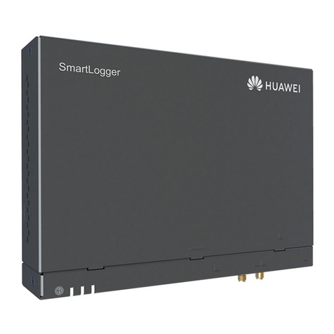
Huawei SmartLogger2000 series User manual

SmartLogger2000-(10-C, 11-C)
User Manual
Issue
Draft A
Date
2017-02-15
HUAWEI TECHNOLOGIES CO., LTD.

Issue Draft A (2017-02-15)
Huawei Proprietary and Confidential
Copyright © Huawei Technologies Co., Ltd.
i
Copyright © Huawei Technologies Co., Ltd. 2017. All rights reserved.
No part of this document may be reproduced or transmitted in any form or by any means without prior
written consent of Huawei Technologies Co., Ltd.
Trademarks and Permissions
and other Huawei trademarks are trademarks of Huawei Technologies Co., Ltd.
All other trademarks and trade names mentioned in this document are the property of their respective
holders.
Notice
The purchased products, services and features are stipulated by the contract made between Huawei and
the customer. All or part of the products, services and features described in this document may not be
within the purchase scope or the usage scope. Unless otherwise specified in the contract, all statements,
information, and recommendations in this document are provided "AS IS" without warranties, guarantees or
representations of any kind, either express or implied.
The information in this document is subject to change without notice. Every effort has been made in the
preparation of this document to ensure accuracy of the contents, but all statements, information, and
recommendations in this document do not constitute a warranty of any kind, express or implied.
Huawei Technologies Co., Ltd.
Address:
Huawei Industrial Base
Bantian, Longgang
Shenzhen 518129
People's Republic of China
Website:
http://www.huawei.com
Email:

SmartLogger2000-(10-C, 11-C)
User Manual
About This Document
Issue Draft A (2017-02-15)
Huawei Proprietary and Confidential
Copyright © Huawei Technologies Co., Ltd.
ii
About This Document
Overview
This document introduces the SmartLogger2000-10-C/SmartLogger2000-11-C
(SmartLogger for short) in terms of installation, cable connections, system operation and
maintenance, and troubleshooting. Readers should understand the SmartLogger features,
functions, and safety precautions provided in this document before installing and operating
the SmartLogger.
The figures provided in this document are for reference only. The actual product appearance
prevails.
You can print the document based on your requirements. Store the paper copy properly for
future use. You can log in to http://support.huawei.com/carrier/, click Product Support, and
search for SmartLogger to view and obtain the latest user manual.
Intended Audience
This document is intended for photovoltaic (PV) plant operators and qualified electrical
technical personnel.
Symbol Conventions
The symbols that may be found in this document are defined as follows.
Symbol
Description
Indicates an imminently hazardous situation which, if not
avoided, will result in death or serious injury.
Indicates a potentially hazardous situation which, if not
avoided, could result in death or serious injury.
Indicates a potentially hazardous situation which, if not
avoided, may result in minor or moderate injury.

SmartLogger2000-(10-C, 11-C)
User Manual
About This Document
Issue Draft A (2017-02-15)
Huawei Proprietary and Confidential
Copyright © Huawei Technologies Co., Ltd.
iii
Symbol
Description
Indicates a potentially hazardous situation which, if not
avoided, could result in equipment damage, data loss,
performance deterioration, or unanticipated results.
NOTICE is used to address practices not related to personal
injury.
Calls attention to important information, best practices and
tips.
NOTE is used to address information not related to personal
injury, equipment damage, and environment deterioration.
Change History
Changes between document issues are cumulative. The latest document issue contains all the
changes made in earlier issues.
Issue Draft A (2017-02-15)
This issue is used for first office application (FOA).

SmartLogger2000-(10-C, 11-C)
User Manual
Contents
Issue Draft A (2017-02-15)
Huawei Proprietary and Confidential
Copyright © Huawei Technologies Co., Ltd.
iv
Contents
About This Document.................................................................................................................... ii
1 Safety Precautions.........................................................................................................................1
2 Product Overview .........................................................................................................................3
2.1 Overview ......................................................................................................................................................................3
2.2 Appearance ...................................................................................................................................................................6
2.3 Nameplate Description ...............................................................................................................................................10
2.4 Typical Networking Scenarios....................................................................................................................................12
2.5 System Wiring Diagram..............................................................................................................................................14
3 Device Installation......................................................................................................................23
3.1 Precautions..................................................................................................................................................................23
3.2 Checking Before Installation ......................................................................................................................................23
3.3 Tools ...........................................................................................................................................................................24
3.4 Determining the Installation Position .........................................................................................................................26
3.5 Installing a SmartLogger ............................................................................................................................................28
3.5.1 Installing a SmartLogger on a Wall .........................................................................................................................28
3.5.2 Installing a SmartLogger Along a Guide Rail..........................................................................................................31
4 Electrical Connection..................................................................................................................35
4.1 Precautions..................................................................................................................................................................35
4.2 Preparing an OT Terminal...........................................................................................................................................35
4.3 Connecting Cables to the Terminal Block on the COM Port......................................................................................36
4.4 Connecting a PE Cable to the SmartLogger ...............................................................................................................37
4.5 Connecting the SUN2000...........................................................................................................................................38
4.5.1 Connection Description ...........................................................................................................................................38
4.5.2 Connecting the SUN2000 Over RS485 ...................................................................................................................38
4.5.3 Connecting the SUN2000 Through AC Power Cables ............................................................................................44
4.5.4 Connecting Multiple SUN2000s..............................................................................................................................45
4.6 Connecting an EMI.....................................................................................................................................................47
4.6.1 Connection Description ...........................................................................................................................................47
4.6.2 Connecting the SmartLogger to an EMI That Supports Standard Modbus-RTU.....................................................47
4.6.3 Connecting the SmartLogger to a Split EMI ...........................................................................................................48
4.7 Connecting a Power Meter .........................................................................................................................................53

SmartLogger2000-(10-C, 11-C)
User Manual
Contents
Issue Draft A (2017-02-15)
Huawei Proprietary and Confidential
Copyright © Huawei Technologies Co., Ltd.
v
4.8 Connecting a Box-type Transformer...........................................................................................................................54
4.9 Connecting a PID Module ..........................................................................................................................................55
4.10 Connecting a Ripple Control Receiver .....................................................................................................................57
4.11 Connecting an Ethernet Network Cable....................................................................................................................60
4.12 Connecting Fiber Jumpers ........................................................................................................................................61
5 System Operation........................................................................................................................63
5.1 Checking Before Power-On........................................................................................................................................63
5.2 System Power-On .......................................................................................................................................................64
6 Man-Machine Interaction..........................................................................................................65
6.1 USB Flash Drive Operation........................................................................................................................................65
6.1.1 Exporting Data.........................................................................................................................................................65
6.1.2 Exporting All Files...................................................................................................................................................66
6.1.3 Importing All Files...................................................................................................................................................68
6.1.4 Upgrading the Application.......................................................................................................................................69
6.1.5 Upgrading the BSP ..................................................................................................................................................70
6.2 NMS Operation...........................................................................................................................................................71
6.3 App Operation.............................................................................................................................................................71
7 WebUI............................................................................................................................................72
7.1 Note ............................................................................................................................................................................72
7.2 Preparations for Login ................................................................................................................................................72
7.3 Logging In to the WebUI ............................................................................................................................................80
7.4 Icon Description..........................................................................................................................................................81
7.5 WebUI Layout.............................................................................................................................................................82
7.6 Overview ....................................................................................................................................................................83
7.6.1 Plant Running Information ......................................................................................................................................83
7.6.2 Active Alarm............................................................................................................................................................83
7.6.3 Plant Yield................................................................................................................................................................84
7.6.4 Performance Data ....................................................................................................................................................85
7.6.5 Device Running Information ...................................................................................................................................85
7.7 Device Monitoring......................................................................................................................................................86
7.7.1 Querying Device Status ...........................................................................................................................................86
7.7.2 SmartLogger ............................................................................................................................................................86
7.7.2.1 Querying Master SmartLogger-Related Information............................................................................................86
7.7.2.2 Querying Slave SmartLogger-Related Information..............................................................................................87
7.7.3 SUN2000 .................................................................................................................................................................88
7.7.3.1 Querying Related Information..............................................................................................................................88
7.7.3.2 Setting Running Parameters (Advanced User) .....................................................................................................88
7.7.3.3 Setting Running Parameters (Special User)..........................................................................................................99
7.7.3.4 Setting a Tracking System ..................................................................................................................................109
7.7.3.5 Setting the LVRT Characteristic Curve............................................................................................................... 110
7.7.4 PLC........................................................................................................................................................................ 110

SmartLogger2000-(10-C, 11-C)
User Manual
Contents
Issue Draft A (2017-02-15)
Huawei Proprietary and Confidential
Copyright © Huawei Technologies Co., Ltd.
vi
7.7.4.1 Querying Related Information............................................................................................................................ 110
7.7.4.2 Setting the STA List............................................................................................................................................ 111
7.7.4.3 Networking Settings ........................................................................................................................................... 112
7.7.5 EMI........................................................................................................................................................................ 113
7.7.5.1 Querying Related Information............................................................................................................................ 113
7.7.5.2 Setting Running Parameters................................................................................................................................ 114
7.7.6 Power Meter........................................................................................................................................................... 117
7.7.6.1 Querying Related Information............................................................................................................................ 117
7.7.6.2 Setting Running Parameters................................................................................................................................ 118
7.7.7 PID......................................................................................................................................................................... 119
7.7.7.1 Querying Related Information............................................................................................................................ 119
7.7.7.2 Setting Running Parameters................................................................................................................................120
7.7.8 Custom Device.......................................................................................................................................................124
7.7.8.1 Querying Related Information............................................................................................................................124
7.7.8.2 Setting Telecontrol Parameters ...........................................................................................................................125
7.7.8.3 Setting Teleadjust Parameters.............................................................................................................................126
7.7.9 IEC103 Device.......................................................................................................................................................127
7.7.9.1 Querying Related Information............................................................................................................................127
7.7.9.2 Setting Telecontrol Parameters ...........................................................................................................................127
7.7.9.3 Setting Teleadjust Parameters.............................................................................................................................128
7.8 Querying Historical Data..........................................................................................................................................129
7.8.1 Querying Historical Alarms...................................................................................................................................129
7.8.2 Querying Operation Logs ......................................................................................................................................129
7.8.3 Exporting Data.......................................................................................................................................................130
7.9 Settings .....................................................................................................................................................................132
7.9.1 User Parameters.....................................................................................................................................................132
7.9.1.1 Setting the Date and Time...................................................................................................................................132
7.9.1.2 Setting Plant Information....................................................................................................................................133
7.9.1.3 Setting Gain Parameters......................................................................................................................................134
7.9.1.4 Setting the Saving Interval..................................................................................................................................135
7.9.2 Communications Parameters .................................................................................................................................135
7.9.2.1 Setting Ethernet Parameters................................................................................................................................135
7.9.2.2 Setting RS485 Parameters ..................................................................................................................................136
7.9.2.3 Setting Power Meter Parameters.........................................................................................................................137
7.9.2.4 Setting NetEco Parameters .................................................................................................................................139
7.9.2.5 Setting Modbus TCP Parameters ........................................................................................................................140
7.9.2.6 Setting IEC103 Parameters.................................................................................................................................141
7.9.2.7 Setting IEC104 Parameters.................................................................................................................................142
7.9.3 Extended Parameters..............................................................................................................................................143
7.9.3.1 Setting FTP Parameters.......................................................................................................................................143
7.9.3.2 Setting Email Parameters....................................................................................................................................144
7.9.4 Port Settings...........................................................................................................................................................145

SmartLogger2000-(10-C, 11-C)
User Manual
Contents
Issue Draft A (2017-02-15)
Huawei Proprietary and Confidential
Copyright © Huawei Technologies Co., Ltd.
vii
7.9.4.1 Setting DO Parameters........................................................................................................................................145
7.9.4.2 Setting USB Parameters......................................................................................................................................147
7.9.5 Remotely Shutting Down SUN2000s in Dry Contact Mode .................................................................................148
7.9.6 Setting DI Parameters............................................................................................................................................151
7.10 Maintenance............................................................................................................................................................152
7.10.1 Firmware Upgrade...............................................................................................................................................152
7.10.2 Product Information.............................................................................................................................................153
7.10.3 Setting Security Parameters.................................................................................................................................153
7.10.4 System Maintenance............................................................................................................................................154
7.10.5 Device Log...........................................................................................................................................................155
7.10.6 Site Test ...............................................................................................................................................................156
7.10.7 Device Management ............................................................................................................................................156
7.10.7.1 Connecting Devices..........................................................................................................................................156
7.10.7.2 Device List........................................................................................................................................................158
7.10.7.3 Exporting Parameters........................................................................................................................................158
7.10.7.4 Resetting Alarms...............................................................................................................................................159
7.10.7.5 Re-collecting Performance Data.......................................................................................................................160
7.10.7.6 Correcting the Total Energy Yield.....................................................................................................................161
8 Power Grid Scheduling............................................................................................................163
8.1 Power Grid Dispatching Modes................................................................................................................................163
8.1.1 Active Power Control.............................................................................................................................................163
8.1.2 Reactive Power Control.........................................................................................................................................164
8.2 Application Scenarios ...............................................................................................................................................165
8.2.1 Local Scheduling ...................................................................................................................................................165
8.2.2 Dry Contact Scheduling.........................................................................................................................................171
8.2.3 AI/DI Scheduling...................................................................................................................................................174
8.2.4 Communication Scheduling...................................................................................................................................177
9 Device Maintenance .................................................................................................................181
9.1 Routine Maintenance................................................................................................................................................181
9.2 Troubleshooting........................................................................................................................................................181
9.3 Alarm List.................................................................................................................................................................183
10 SmartLogger Disposal............................................................................................................188
11 Technical Specifications ........................................................................................................189
A Product User Lists ....................................................................................................................192
B Certification Declaration.........................................................................................................193
C Acronyms and Abbreviations................................................................................................195

SmartLogger2000-(10-C, 11-C)
User Manual
1 Safety Precautions
Issue Draft A (2017-02-15)
Huawei Proprietary and Confidential
Copyright © Huawei Technologies Co., Ltd.
1
1 Safety Precautions
Read the safety precautions carefully. Otherwise, human injury and equipment damage may
occur.
Personnel Requirements
Only qualified and trained electrical technicians are allowed to install and operate the
SmartLogger.
Operators should understand the components and functioning of a grid-tied PV power
system, and they should be familiar with relevant local standards.
Read this document thoroughly before operations. Huawei shall not be liable for any
consequence caused by violation of the storage, transportation, installation, and operation
regulations specified in this document.
Label Protection
Do not tamper with any signs on the SmartLogger enclosure because these signs contain
important information about safe operation.
Do not remove or damage the nameplate at the rear of the SmartLogger enclosure
because it contains important product information.
Installation
Ensure that the SmartLogger is not connected to a power supply and is not powered on
before starting installation.
Install the SmartLogger in an environment with good ventilation to ensure efficient and
long-term system performance.
Ensure that the heat dissipation holes of the SmartLogger are not blocked.
During installation, do not touch any component inside the enclosure except the wiring
terminals at the bottom.
Install the SmartLogger in a dedicated area.

SmartLogger2000-(10-C, 11-C)
User Manual
1 Safety Precautions
Issue Draft A (2017-02-15)
Huawei Proprietary and Confidential
Copyright © Huawei Technologies Co., Ltd.
2
Operation
Perform operations in strict accordance with safety precautions specified in this document and
other relevant documents.
When operating Huawei equipment, you must follow the local laws and regulations.
Maintenance and Replacement
A faulty SmartLogger requires overall maintenance. Contact the dealer if the
SmartLogger is faulty.
With sufficient knowledge of this document, maintain the SmartLogger by using proper
tools and testing equipment.
When maintaining the SmartLogger, wear electrostatic discharge (ESD) gloves and
comply with ESD precautions.
The device has multiple inputs. Switch off all inputs before maintenance.

SmartLogger2000-(10-C, 11-C)
User Manual
2 Product Overview
Issue Draft A (2017-02-15)
Huawei Proprietary and Confidential
Copyright © Huawei Technologies Co., Ltd.
3
2 Product Overview
2.1 Overview
Function
The SmartLogger is a highly integrated device dedicated for monitoring and managing the PV
power system. It converges ports, converts protocols, collects and stores data, and centrally
monitors and maintains devices in the PV power system.
Features
The SmartLogger provides the following features:
Wide application
−Industrial-grade application, wide temperature range: –40°C to +60°C
−High altitude: applicable at an altitude of 4000 m
Various communication modes
−Bluetooth
Has a built-in Bluetooth module through which the SUN2000 APP (APP for short)
connects to the SmartLogger for parameter configuration and device maintenance.
The SmartLogger Bluetooth is named as LOG+the last eight figures of the SN of
the SmartLogger.
−Optical fiber ring switch
Provides two 100M Ethernet optical ports that support RSTP and STP to implement
fiber ring networking. If RSTP is used, fiber ring protection can be completed
within 10 seconds. If STP is used, fiber ring protection can be completed within 60
seconds.
−PLC
The SmartLogger-10-C has a built-in PLC CCO module through which
southbound devices connect to the SmartLogger over AC power cables.
The built-in PLC CCO module has the maximum voltage class of 800 VAC.
−Ethernet electrical port
Provides two 10/100M Ethernet electrical ports that can be used as southbound
ports to connect to southbound devices or used as northbound ports to connect to an
NMS.

SmartLogger2000-(10-C, 11-C)
User Manual
2 Product Overview
Issue Draft A (2017-02-15)
Huawei Proprietary and Confidential
Copyright © Huawei Technologies Co., Ltd.
4
A southbound port connects to a downstream device for collecting data and setting parameters.
Southbound devices include the SUN2000, environmental monitoring instrument (EMI), power
meter, box-type transformer, and PID module.
A northbound port connects to an upstream NMS for uploading data.
−RS485
Supports six RS485 routes and access of devices that use Modbus-RTU,
IEC103, and DL/T645.
RS485 supports the modbus-slave mode. If RS485 is set to Modbus-Slave, the
SmartLogger works in slave mode and can interwork with a third-party device,
such as a data collector and a communication manager.
Graphical data
−In addition to displaying the electricity yield and real-time monitoring information
in graphic and text format, the embedded WebUI can also display performance data
of power stations and devices in tables or curves.
−The APP displays the electricity yield and real-time monitoring information in
graphic and text format.
Centralized monitoring
−Manages up to 200 devices in centralized mode and supports the access of up to 150
SUN2000s.
−Allows you to monitor and manage the PV power system on the embedded WebUI,
for example, viewing real-time information about power stations, devices, and
faults, setting device parameters, and maintaining devices in remote mode.
−Allows you to monitor the devices in the PV power system on theAPP in real time,
such as viewing information about power stations, devices, products, and faults,
setting device parameters, and maintaining devices.
Easy maintenance
−Allows users to upgrade the firmware of the SmartLogger and export data by using
a USB flash drive.
−Allows you to upgrade the firmware of the SmartLogger, SUN2000, PLC module,
and PID module, and export logs and data over the embedded WebUI.
−Allows you to manage the devices connecting to the SmartLogger, upgrade the
firmware of these devices, exports data from these devices, and classify and query
alarms over the app.
Intelligent management
−Automatically searches for and accesses Huawei SUN2000s, PLC modules, and
PID modules. If you import a parameter configuration table, the SmartLogger can
access third-party devices that support Modbus-RTU and IEC103.
−Automatically assigns RS485 addresses to the connected Huawei SUN2000s and
PID modules, and allows for RS485 address adjustment based on ESNs to facilitate
remote configuration and maintenance.
−Supports remote configuration of SUN2000 parameters over the embedded WebUI
and synchronizes the parameters from one SUN2000 to other SUN2000s in batches.
−Automatically collects the data generated during the communication disconnection
from the SUN2000 or manually collects the data over the embedded WebUI after
the connection resumes.
Remote maintenance

SmartLogger2000-(10-C, 11-C)
User Manual
2 Product Overview
Issue Draft A (2017-02-15)
Huawei Proprietary and Confidential
Copyright © Huawei Technologies Co., Ltd.
5
−Simultaneously connects to multiple NMSs (including Huawei and third-party
NMSs) over Modbus-TCP and IEC104. Huawei NMS features centralized O&M,
big data analytics, intelligent diagnosis, and mobile O&M.
−Supports connection to a third-party NMS over File Transfer Protocol (FTP).
−Sends electricity yield and alarms to users by emails.
Grid scheduling
−The SmartLogger supports various power grid scheduling modes and therefore can
meet the requirements of power grid companies in different countries.
−Implements rapid active power control and reactive power compensation for all the
SUN2000s connecting to the SmartLogger.
Model Description
Model
PLC Module Configured?
Remarks
SmartLogger2000-10-C
Yes
The built-in
Bluetooth module
supports both
Android APP and
iOS APP.
SmartLogger2000-11-C
No
The SmartLogger2000-10-C is integrated with the PLC central coordinator (CCO) that can work
with the SUN2000 integrated with the PLC station (STA) to implement PLC networking over power
cables.
The SmartLogger2000-11-C is not integrated with the PLC CCO. If PLC networking with the
SUN2000 integrated with the PLC STA is required, connect a PLC CCO to the
SmartLogger2000-11-C.
This document describes the typical networking and cable connections by using the
SmartLogger2000-10-C as an example.

SmartLogger2000-(10-C, 11-C)
User Manual
2 Product Overview
Issue Draft A (2017-02-15)
Huawei Proprietary and Confidential
Copyright © Huawei Technologies Co., Ltd.
6
2.2 Appearance
Front View of the Shell
Figure 2-1 SmartLogger front view (unit: mm)
(1) Indicators
Table 2-1 Description of the LED indicators (from left to right)
Indicator (Silk
Screen)
Status
Meaning
RUN indicator
Green off
The SmartLogger is not
powered on.
Blinking green at short intervals (on
for 0.125s and then off for 0.125s)
The SmartLogger and
NMS (Huawei NetEco or
a third-party NMS) are not
connected or the
communication between
them is interrupted.
Blinking green at long intervals (on
for 1s and then off for 1s)
The SmartLogger properly
communicates with the
NMS (Huawei NetEco or
a third-party NMS).
Alarm/maintenance
indicator (ALM)a
Alarm status
Red off
The SmartLogger and the
devices accessing it do not
generate any alarm.
Blinking red at
long intervals (on
for 1s and then off
for 4s)
The SmartLogger or the
devices accessing it
generate warnings.

SmartLogger2000-(10-C, 11-C)
User Manual
2 Product Overview
Issue Draft A (2017-02-15)
Huawei Proprietary and Confidential
Copyright © Huawei Technologies Co., Ltd.
7
Indicator (Silk
Screen)
Status
Meaning
Blinking red at
short intervals (on
for 0.5s and then
off for 0.5s)
The SmartLogger or the
devices accessing it
generate minor alarms.
Steady red
The SmartLogger or the
devices accessing it
generate major alarms.
Maintenance
status
Green off
No local maintenance is
underwayb.
Blinking green at
long intervals (on
for 1s and then off
for 1s)
Local maintenance is in
progress.
Steady green
Local maintenance
succeeds.
Blinking green at
short intervals (on
for 0.125s and then
off for 0.125s)
Local maintenance fails.
3G/4G indicator
-
Reserved.
Bluetooth indicator
(BLE)
Green off
You have not logged in to
the APP or login failed.
The SmartLogger is not
connected to the APP or
the communication has
been interruptedc.
Blinking green at long intervals (on
for 1s and then off for 1s)
You have successfully
logged in to the APP.
a: If an alarm and local maintenance happen concurrently, the alarm/maintenance indicator
shows the near-end maintenance state first. After the USB flash drive is removed, the
indicator shows the alarm state.
b: Local maintenance refers to operations performed by connecting a USB flash drive to the
SmartLogger USB port, such as full data import and export using a USB flash drive.
c: After the communication between the SmartLogger and the APP fails, the disconnection
is normal if the green indicator goes off immediately, and is abnormal if the indicator goes
off after blinking slowly for 30s.

SmartLogger2000-(10-C, 11-C)
User Manual
2 Product Overview
Issue Draft A (2017-02-15)
Huawei Proprietary and Confidential
Copyright © Huawei Technologies Co., Ltd.
8
Side View of the Shell
Figure 2-2 SmartLogger side view (unit: mm)
(1) Heat dissipation hole
Rear View of the Shell
Figure 2-3 SmartLogger rear view (unit: mm)
(1) Wall-mounting ears

SmartLogger2000-(10-C, 11-C)
User Manual
2 Product Overview
Issue Draft A (2017-02-15)
Huawei Proprietary and Confidential
Copyright © Huawei Technologies Co., Ltd.
9
Bottom of the Shell
Figure 2-4 Bottom view of the SmartLogger
Table 2-2 Port description
No.
Port (Silk
Screen)
Function
Description
1
RF1, RF2
Reserved
Reserved.
2
12V OUT
12 V DC output
Provides 12 V DC power supply with a
maximum current of 100 mA.
3
12V IN
12 V DC input
Connects to a power adapter.
4
USB
USB port
Connects a USB flash drive.
5
SFP1, SFP2
Ethernet optical
port
Connects to an ATB or another cascaded
SmartLogger.
6
ETH1, ETH2
Ethernet electrical
port
Connects to an Ethernet switch, router,
POE module, or PC.
7
DO
Digital parameter
output
Relay output.
8
COM1–COM
6
RS485
communication
Six RS485 ports that can be connected to
devices such as the SUN2000, box-type
transformer, power meter, or EMI.
9
Default
Default key
Resets and restarts the Bluetooth module or
resets the SmartLogger IP address to the
default IP addressa. The default IP address
is 192.168.0.10.
10
AC1, AC2
AC power cable
ports
SmartLogger2000-10-C: Connects to
the A/B/C three-phase input, and used
for PLC with the SUN2000 over AC
power cables. If PLC function is not
used, you do not have to connect cables
to these ports.
SmartLogger2000-11-C: left blank
11
External
grounding
N/A

SmartLogger2000-(10-C, 11-C)
User Manual
2 Product Overview
Issue Draft A (2017-02-15)
Huawei Proprietary and Confidential
Copyright © Huawei Technologies Co., Ltd.
10
No.
Port (Silk
Screen)
Function
Description
12
AI1–AI7
Analog input
AI1 supports 0–10 V voltage input
(passive); AI2–AI7 support 0–20 mA and
4–20 mA current input (passive).
13
PT1, PT2
Analog input
PT1 supports the connection to a
three-wire or two-wire PT100/PT1000
temperature sensor.
PT2 supports the connection to only a
two-wire PT100/PT1000 temperature
sensor.
13
AO1–AO4
Analog output
4–20 mA and 0–20 mA current output.
14
DI1–DI8
Digital parameter
input
Connects to a dry contact input.
a:
If the APP fails to connect to the SmartLogger or you have forgotten the IP address, you
can press the Default key to reset the Bluetooth module or restore the IP address to the
default IP address (192.168.0.10).
To reset and restart the Bluetooth module, press and hold down the Default key for
3–10s until the BLU indicator blinks at short intervals (0.125s on and 0.125s off) and all
other indicators are off, and then release the Default key.
To restore the IP address to the default IP address, press and hold down the Default key
for more than 10s until the RUN indicator blinks at short intervals (0.125s on and
0.125s off) and all other indicators are off, and then release the Default key. The
operation is valid within 5 minutes.
2.3 Nameplate Description
A nameplate is attached at the back of the SmartLogger. The content of the nameplate
includes the SmartLogger model, rated power specifications, and certification marks. Figure
2-5 shows the nameplate of the SmartLogger2000-10-C.

SmartLogger2000-(10-C, 11-C)
User Manual
2 Product Overview
Issue Draft A (2017-02-15)
Huawei Proprietary and Confidential
Copyright © Huawei Technologies Co., Ltd.
11
Figure 2-5 Nameplate
(1) Trademark and product model
(2) Rated power specifications
(3) Compliance symbols
(4) Company name and place of
manufacture
The nameplate figure is for reference only. The actual nameplate prevails.
Table 2-3 Compliance symbols
Symbol
Name
Meaning
Environmentally friendly
use period (EFUP) label
This product does not
pollute the environment
during a specified period.
EU waste electrical and
electronic equipment
(WEEE) label
Do not dispose of the
SmartLogger as household
garbage. For details about
how to deal with the
undesirable SmartLogger,
refer to 10 SmartLogger
Disposal.

SmartLogger2000-(10-C, 11-C)
User Manual
2 Product Overview
Issue Draft A (2017-02-15)
Huawei Proprietary and Confidential
Copyright © Huawei Technologies Co., Ltd.
12
2.4 Typical Networking Scenarios
Fiber+RS485/PLC Networking
A fiber network is classified into a ring network and a star network, as shown in Figure 2-6
and Figure 2-7 respectively.
In the fiber networking, the SmartLogger connects to an inverter over an RS485
communications cable or anAC power cable, connects to a box-type transformer over an
RS485 communications cable or an Ethernet network cable, and connects to southbound
devices such as the EMI and power meter over RS485 communications cables.
The SmartLogger can work with the SUN2000 equipped with the PLC STA module over an embedded
or external PLC CCO module to implement PLC networking over power cables.
Figure 2-6 Fiber ring network diagram
The SmartLogger provides two 100M Ethernet optical ports to implement ring networking.
A maximum of 16 SmartLoggers can be connected to form a fiber ring network. Each SmartLogger
can connect to southbound devices such as the inverter, EMI, and power meter.
Multiple fiber ring networks can converge over an Ethernet switch or SmartLogger and then connect
to an NMS.
Other manuals for SmartLogger2000 series
4
This manual suits for next models
2
Table of contents
Other Huawei Data Logger manuals

Huawei
Huawei FusionModule500 User manual

Huawei
Huawei SmartLogger3000 User manual

Huawei
Huawei FusionModule 1000A20 User manual

Huawei
Huawei SmartLogger1000 User manual

Huawei
Huawei SmartLogger3000 User manual

Huawei
Huawei SmartLogger2000-10-B-JP User manual

Huawei
Huawei FusionModule500 Technical specifications

Huawei
Huawei Atlas 500 Quick reference guide

Huawei
Huawei FusionModule 1000B Operating manual

Huawei
Huawei SmartLogger3000 User manual