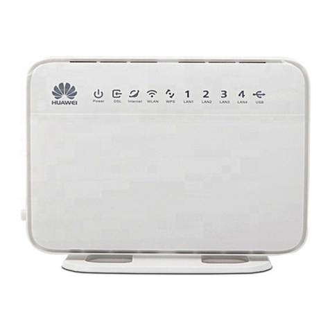
Huawei EchoLife HG520s User manual

EchoLifeHG520sHomeGateway
UserManual
HUAWEITECHNOLOGIES CO., LTD.

EchoLife HG520s Home Gateway User Manual
HUAWEI TECHNOLOGIES CO., LTD.

HUAWEI TECHNOLOGIES CO., LTD.
Huawei AdministrationBuilding
Bantian,LonggangDistrict
Shenzhen,518129
PeoplesRepublicofChina
www.huawei.com
202013

EchoLifeHG520s HomeGatewayUserManual
Issue
02
Date2006-09-15
No. 202013
Huawei TechnologiesCo., Ltd.
Address: AdministrationBuilding,HuaweiTechnologiesCo.,Ltd.,
Bantian,LonggangDistrict, Shenzhen, 518129,Peoples
RepublicofChina
Website: http://www.huawei.com
Email: terminal@huawei.com
Copyright Huawei Technologies Co., Ltd. 2006. All rightsreserved.
Nopartof thisdocumentmaybereproducedortransmittedinanyformorby
anymeanswithoutpriorwrittenconsentof HuaweiTechnologiesCo.,Ltd.
Trademarks and Permissions
andotherHuaweitrademarksaretrademarksofHuaweiTechnologies
Co.,Ltd.
Allothertrademarksandtradenamesmentionedinthisdocument arethe
propertyoftheirrespectiveholders.
Notice
Theinformationinthisdocumentissubject tochangewithoutnotice.Every
effort hasbeenmadeinthepreparationofthisdocumenttoensureaccuracy
ofthecontents, butall statements,information, andrecommendationsinthis
documentdonotconstitutethewarrantyofanykind, express orimplied.
Thisproduct hasbeendesignedtocomplywiththerequirementson
environmentalprotection.Fortheproperstorage,useanddisposalofthis
product, nationallawsandregulationsmustbeobserved.

SafetyPrecautions
BasicRequirements:
lRead thismanualcarefullybeforeinstallingandusingthe
equipment.
lTakewaterproofmeasuresduringstorage,transportationand
operation oftheequipment.
lAvoidcollision during storage,transportation and operationofthe
equipment.
lWithoutpriorwrittenconsentfromHuawei,no companyorindividual
isallowedtodecompile,disassemble,modifyorreverseengineer
theequipmentandshallbesolelyresponsibleforanyeffectresulted
fromsuchaction.
EnvironmentalRequirements:
lPlacetheequipmentinawell-ventilatedplace.Avoiddirect
irradiationof anystronglight(suchassunlight).
lKeeptheequipmentclean.
lPlacetheequipmentonaflatandstableplatformwhichisbeyond
thereachofchildren.
lDonot placeheavyobjectsontheequipment.
lMaintainatleast10cmspacearound theequipmentforheat
dissipation. Donot covertheequipment withanyobject orblock the
ventilationholesof theequipment.
lKeeptheequipmentawayfromapplianceswithastrongelectric
fieldormagneticfield,suchasamicrowaveovenandarefrigerator.
Usage:
lUseonlythepoweradapterprovidedwiththeequipment.
lThepowersupplymust meettheequipment specifications.
lBeforeplugging orunplugging thecables,turnoff theequipment
and unplugthepowersupply.
lInalightningstorm,turnoff theequipmentandunplugthepower
supply,toavoidlightningstrike.
lUnplugthepowersupplyiftheequipmentisnotusedforalong
time.

lThetemperatureoftheequipmentshellgoesupwhenusedforlong
hours.Thisisanormalphenomenon.
Cleaning:
lBeforecleaningtheequipment, turnofftheequipmentandunplug
thepowersupply.
lClean theequipmentshellwithapieceofsoftcloth.
lDonotsprayliquidontotheequipment,toavoiddamagetothe
internalcircuit.
lKeepthepowersocketclean anddry,toavoidelectricshock or
otherdangers.

i
TableofContents
Chapter1Introduction......................................................................1
1.1Functionsand Features......................................................1
1.2HardwareConfiguration......................................................1
1.2.1Front Panel...............................................................2
1.2.2RearPanel...............................................................4
1.2.3Splitter......................................................................4
Chapter2Installation ofthe HG520s................................................6
2.1Preparation.........................................................................6
2.2Connecting the HG520s......................................................6
2.3Establishing Configuration Environment..............................8
2.3.1ParameterConfiguration...........................................8
2.3.2Steps........................................................................8
2.4Web Configuration Page.....................................................9
Chapter3ServiceConfiguration.....................................................11
3.1Method.............................................................................11
3.1.1ProtocolModel........................................................11
3.1.2Steps......................................................................12
3.2ServiceModesofthe HG520s...........................................12
3.3Configuring the Bridge Mode.............................................14
3.3.1Preparation.............................................................14
3.3.2Steps......................................................................15
3.4Configuring the PPPoEMode...........................................17
3.4.1Preparation.............................................................17

ii
3.4.2Steps......................................................................18
3.5Configuring the PPPoAmode...........................................20
3.6Configuring the RFC2684BMode......................................20
3.6.1Preparation.............................................................20
3.6.2Steps......................................................................21
3.7Configuring the RFC2684 (IPoA)Mode.............................23
3.8Configuring the Wireless Mode.........................................23
3.8.1Preparation.............................................................23
3.8.2Steps......................................................................24
Chapter4OtherSettings................................................................27
4.1Configuring the QoS.........................................................27
4.2Changing the IPAddress ofthe LANof theHG520s..........28
4.3Changing the AdministratorPasswordofthe HG520s.......29
4.4Restoring the DefaultFactory Settings..............................29
Chapter5Troubleshooting.............................................................31
5.1Quick FailureLocation......................................................31
5.2FAQs................................................................................32
Chapter6Technical Specifications.................................................34
Chapter7Appendix.......................................................................35
7.1DefaultFactory Settings....................................................35
7.1.1Common DefaultParameters..................................35
7.1.2Default PVCParameters.........................................35
7.2Abbreviations....................................................................36

1
Chapter1Introduction
Thischapterintroducesfunctionsand structureoftheEchoLife
HG520sHomeGateway(hereinafterreferred toasthe HG520s).
1.1FunctionsandFeatures
The HG520sisatypeofAsymmetricDigital SubscriberLine
(ADSL)terminal.Data,video and audioaretransmitted through the
commontelephone line at ahigherratebythe HG520s.
The featuresofthe HG520sare:
lHigh transmission rate:The maximumdownstreamrateis24
Mbit/s;the maximumupstreamrateis
1.2Mbit/s.
lStrong network adaptability:The HG520scan be
interconnectedwithmultipleDigitalSubscriberLine Access
Multiplexer(DSLAMs).
lStrong maintainability:TheHG520sprovidesmultiple
indicatorstatus, whichisconvenienttolocatefailures.
lEasyoperation: The HG520shasasimpleoperationforthe
configuration page.
1.2HardwareConfiguration
Thissection introducesthe appearanceand the structureofthe
HG520s.

2
&Note:
Figuresofthe frontpaneland the rearpanelareonlyforyourreference.
1.2.1Front Panel
Figure1-1showsthe frontpanelof the HG520s.
WLAN LAN4 LAN3LAN2LAN1INTERNETADSL POWER
Figure1-1FrontpaneloftheHG520s
Table1-1showsindicatorsinthe frontpanel.
Table1-1Indicatorsinthefrontpanel
Indicator Color Status
Description
On TheHG520sispoweredon.
POWER Green Off TheHG520sispoweredoff.
On TheDSLconnectionis
established.
Blinking
Therearedatabeingtransmitted
intheDSLconnectionortheDSL
connection isbeingactivated.
ADSL Green
Off Thetelephonelineisnot
connectedortheDSLconnection
isnotestablished.

3
Indicator Color Status
Description
On TheembeddedPPPoEand
PPPoAdial-upsoftheHG520s
aresuccessful,but thereisno
datatransmission.
Blinking
Therearedataarebeing
transmittedinthe INTERNET
interface.
INTERNET
Green
Off TheHG520sisinthebridgemode
orthePPPoE/PPPoAconnection
isnotestablished.
On Theconnection isestablishedin
theLANinterface.
Blinking
Therearedatabeing transmitted
intheLANinterface.
LAN1–4 Green
Off Noconnectionisestablishedin
theLANinterface.
On Theconnection isestablishedin
the WLAN interface.
Blinking
Therearedatabeing transmitted
inthe WLAN interface.
WLAN Green
Off Noconnectionisestablishedin
the WLAN interface.
Note:
PPPoE= Point-to-Point overEthernet
PPPoA= Point-to-Point overATM
LAN= LocalAreaNetwork
WLAN= Wireless LocalArea Network
&Note:
Ifthe HG520sfailstoactivate,ittriesagainafteran interval.The ADSL
LINKindicatorisoff during the interval,lasting forabout1minute.

4
1.2.2RearPanel
Figure1-2showsthe rearpaneloftheHG520s.
ADSL
LAN1 LAN2 LAN3 LAN4
ON/OFF
POWER
RESET
Figure1-2RearpaneloftheHG520s
Table1-2 showsinterfacesand buttonsinthe rearpanel.
Table1-2InterfacesandButtonsintherearpanel
Interface/Button Description
Antenna Antenna forwireless Internetaccess.
ADSL ADSLinterface.
Toconnectthetelephonejack orasplitterthrougha
telephoneline.
LAN1–4 Ethernetinterfaces.
Toconnect LANnetworkdevices(suchasacomputer
and aswitch).
RESET
TorestarttheHG520s, press the RESET buttonand
releaseit withinthree seconds.Torestorethedefault
settingsoftheHG520s,pressthe RESET buttonand
releaseitafterthree seconds. Onceyouusethis
function,allyourcustomsettingswill belost. Therefore,
pleasebecarefulwhenusingit.
POWER Connecttothepoweradapter.
ON/OFF Poweron/offtheHG520s.
1.2.3Splitter
The external splittercan efficientlyreducethe signal disturbance
on the telephone line.When voiceanddataaretransmitted through the

5
sametelephone line atthe sametime,you need an externalsplitterto
separatethe voiceand datasignals:
lLINE: Connecting tothe phone jackon the wall.
lPHONE:Connecting tothe telephone.
lMODEM: Connecting tothe ADSLinterfaceof theHG520s.

6
Chapter2InstallationoftheHG520s
Thischapterintroducesthe installation when the HG520sisused
forthe first time.
2.1Preparation
Connectyourcomputerwiththe HG520sthrough the Ethernet
interfaces. Beforeinstalling the HG520s,makesurethatyourcomputer
isequipped withthe network card
2.2Connecting the HG520s
Figure2-1showsthe connection ofthe HG520s.
ADSL
LAN1 LAN2 LAN3 LAN4
ON/OFF
POWER
RESET
(10)
(6)
(7)
(8)
(9)
(5)
(1)
(2)
(3)(3)(3) (4)
(3)
(1)Poweradaptor (2)Switch (3)Computer
(4)Set-TopBox (5)Modemportof
splitter (6)Lineinterface
ofsplitter
(7)Phoneinterface
ofsplitter (8)Splitter (9)Phone
(10)PhoneJack
Figure2-1ConnectionoftheHG520s

7
Connect the HG520sasfollows:
Caution:
Beforeconnecting the HG520s, poweroffthe HG520sand your
computer.
(1)Connectthe interfacesofthe splitterwiththe corresponding
equipmentbyusing the telephone line.
lConnect the LINE interfaceof the splitterwiththe telephone
jack on the wall.
lConnectthe MODEM interfaceof the splitterwiththe ADSL
interfaceofthe HG520s.
lConnectthe PHONE interfaceofthe splitterwiththe
interfaceofthe telephone line.
(2)ConnecttheEthernetinterfaceoftheHG520swiththe
Ethernetinterfaceofthe computerbyusing Ethernetcable.
(3)Plug the outputend ofthe provided poweradapterintothe
powerinput interfaceofthe HG520s; plug the otherend into
the powersocket.
(4)Press the POWER button of the HG520sinthe rearpanelto
poweron the HG520s.
Check the powerindicatorinthe frontpanelofthe HG520s.If
itison,the HG520sispowered on.

8
2.3EstablishingConfigurationEnvironment
You can configuretheHG520son the Web configurationpage.
Thissectiondescribesthe process toestablishtheconfiguration
environment of the HG520s.
2.3.1ParameterConfiguration
Beforeestablishing the configurationenvironment, set the
following parameters.
Table2-1Parametersfortheconfigurationenvironment
Name Description
Administratorusernameand
passwordoftheHG520s
Default:
lUsername: admin
lPassword: admin
IPaddress and subnetmask
oftheLANoftheHG520s
Default:
lIPaddress: 192.168.1.1
lSubnetmask: 255.255.255.0
IPaddress and subnetmask
ofthecomputer
Set themtobeinthesamenetwork
segment astheIPaddressof theLANofthe
HG520s
Forexample:
lIPaddress: 192.168.1.100
lSubnetmask: 255.255.255.0
2.3.2Steps
Followthe stepstoestablishthe configurationenvironment.
Step
To... Do...
1 Connectthe
HG520s FordetailstoconnecttheHG520s,referto2.2
"ConnectingtheHG520s."

9
Step
To... Do...
2 Makesurenot
tousetheproxy
server.
Theprocess tounselectthisfunctionisdescribed
asfollows(takingInternet Explorer6.0asan
example):
(1)StarttheInternetExplorer.Select Tools >
Internet Options... todisplaythe Internet
Options dialog box.
(2)Selectthe Connections tab.Click LAN
Settings....
(3)Deselect Use aproxyserverforyourLAN
(Thesesettingswillnotapplytodial-up
orVPNconnections).
3
Log intothe
Web
configuration
page
(1)IntheaddressbarofInternetExplorer,enter
http://192.168.1.1 (thedefaultIPaddress of
theHG520s).Thenpress Enter.Thelogin
windowisdisplayed.
(2)Entertheusernameandthepasswordofthe
administratorintheloginwindow.
When thepasswordisauthenticated,you
can access theWeb configurationpage.
&Note:
Afterconfiguring the parametersoftheHG520s, configurethe
computeraccording tothe configuration statusof the HG520s. For
details, pleaserefertoChapter3"ServiceConfiguration."
2.4Web Configuration Page
The Webconfiguration page ofthe HG520sisdividedintotwo
parts:
lThe navigationtree:Itisontheleftside ofthepage.It
providesyou toaccess todifferent configuration pages.

10
lConfiguration area:It ison the rightside ofthe page.

11
Chapter3Service Configuration
Thischapterintroducesthe method forconfiguring the HG520s.
&Note:
The figuresinthefollowing configuration operationsareonlyforyour
reference.
3.1Method
3.1.1ProtocolModel
Figure3-1showsthe protocolmodelofforthe connection between
the HG520sand the DSLAM atthe officeend.
PHY ADSL PHYADSL
ATM
PHY
MAC MACATM
(1) (2) (3)
PVC
Figure3-1Protocolmodel
(1)Computer (2)HG520s (3)DSLAM

12
The transmission between the HG520sand the DSLAM isbased
on theasynchronoustransfermode(ATM). Inthe serviceconfiguration
of the HG520s, you need toconfigureparameters,forexample,the
permanentvirtual channel(PVC).
3.1.2Steps
The servicemodesof HG520scan be realized byconfiguring the
corresponding working parameters.
The stepstorealizeaservicemode aredescribed asfollows.
Step
To... Do...
1 Establishthe
configuration
environment
Referto2.3"Establishing Configuration
Environment."
2 Configurethe
HG520s
(1)Select thePVCtobeconfigured.
(2)SelecttheservicemodeofthisPVCand
configuretheparametersofthePVC.
(3)Configurefunctionsaccording tothe
requirements.
Forexample,configuretheDHCPfunction.
(4)Savetheconfigurationandrebootthe
HG520s.
3 Configureyour
computer
Configuretheparametersofthenetworkcardfor
thecomputerorinstallthedial-up softwareinthe
computeraccording totheservicemodeof the
HG520s.
Note:
DHCP=DynamicHost Configuration Protocol
3.2ServiceModesof theHG520s
The HG520ssupportsmultipleservicemodesand the
configuration of the DSLAMatthe officeend shouldbe considered
Other manuals for EchoLife HG520s
2
Table of contents
Other Huawei Gateway manuals

Huawei
Huawei DG8245W2 User manual

Huawei
Huawei HG532c User manual

Huawei
Huawei E960 HSDPA User manual

Huawei
Huawei eA680-950 User manual

Huawei
Huawei H350L/B890-66s User manual

Huawei
Huawei eA360 Series User manual

Huawei
Huawei HG532s User manual

Huawei
Huawei eA380-123 User manual

Huawei
Huawei eA380 User manual

Huawei
Huawei RRU3201 User manual

Huawei
Huawei HG622 User manual

Huawei
Huawei BC510 User manual

Huawei
Huawei B686 User manual

Huawei
Huawei B2268H User manual

Huawei
Huawei B933 series User manual
Huawei
Huawei ME60 Series Instructions for use

Huawei
Huawei eSpace EGW1520A User manual

Huawei
Huawei HG532t User manual
Huawei
Huawei HG655d User manual

Huawei
Huawei HG256 User manual