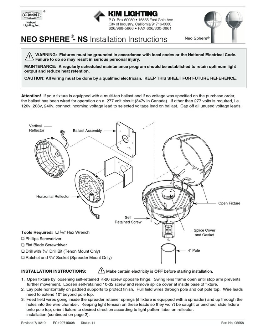
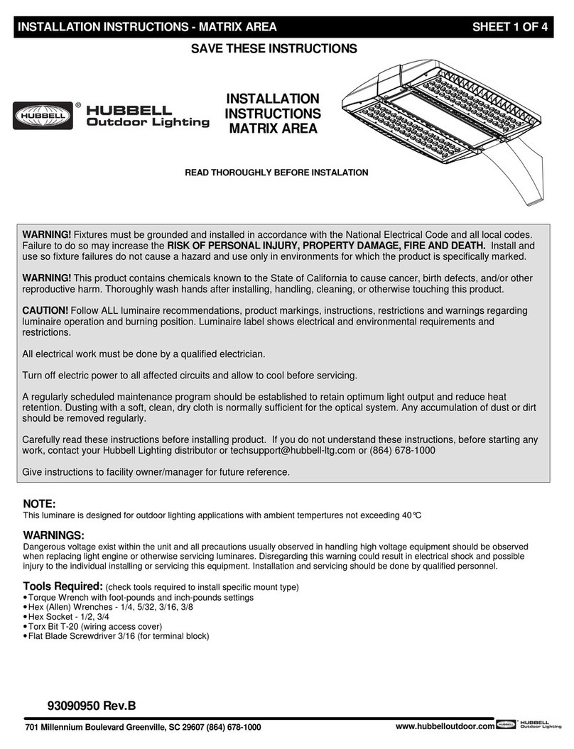
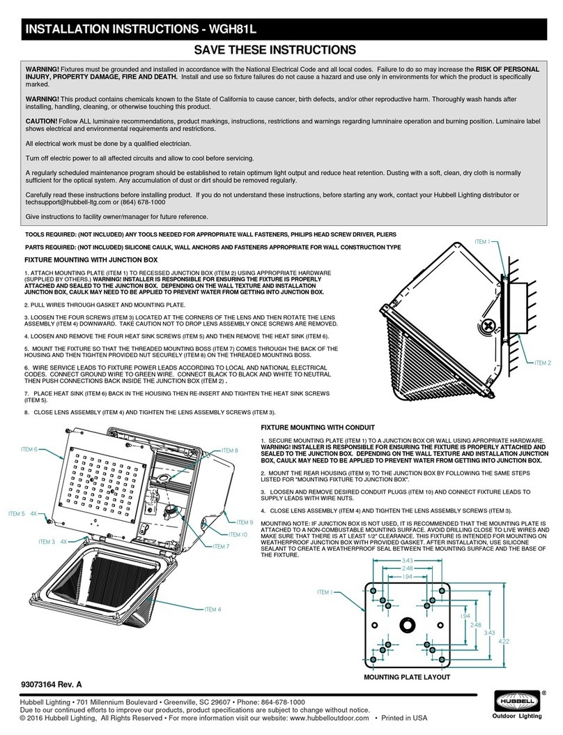
Hubbell KIM LIGHTING VSBC User manual
Other Hubbell Outdoor Light manuals
Hubbell
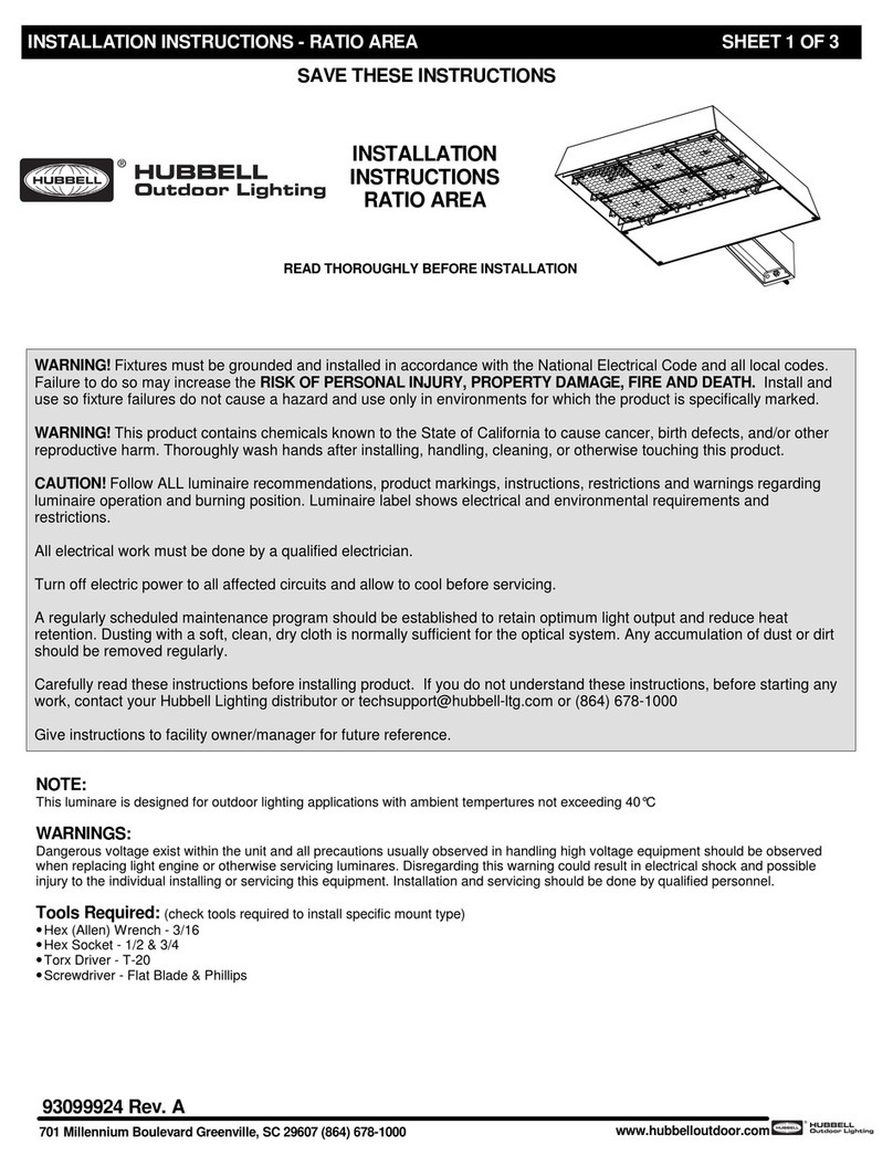
Hubbell RATIO AREA User manual

Hubbell
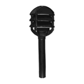
Hubbell AIRO User manual
Hubbell
Hubbell KIM Path Pilot KLV101 User manual

Hubbell
Hubbell KIM Lighting SCARAB Accent Series User manual

Hubbell
Hubbell Kim Lighting KLV Series User manual

Hubbell
Hubbell Killark KFLX Series Instruction Manual

Hubbell
Hubbell PERIMALITER III Service manual

Hubbell
Hubbell KIM LIGHTINING C24 User manual

Hubbell
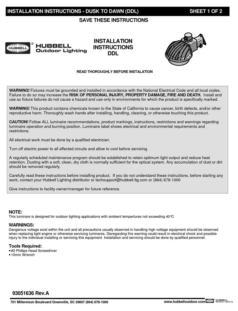
Hubbell LNC4 User manual
Hubbell
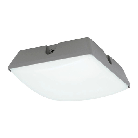
Hubbell DDL-9L1 User manual
Hubbell
Hubbell LUMASQUARE User manual
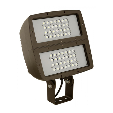
Hubbell
Hubbell FXL LED FLOOD User manual
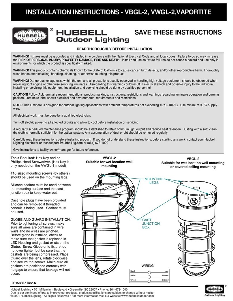
Hubbell
Hubbell VBGL-2 User manual
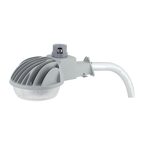
Hubbell
Hubbell DDL Series User manual
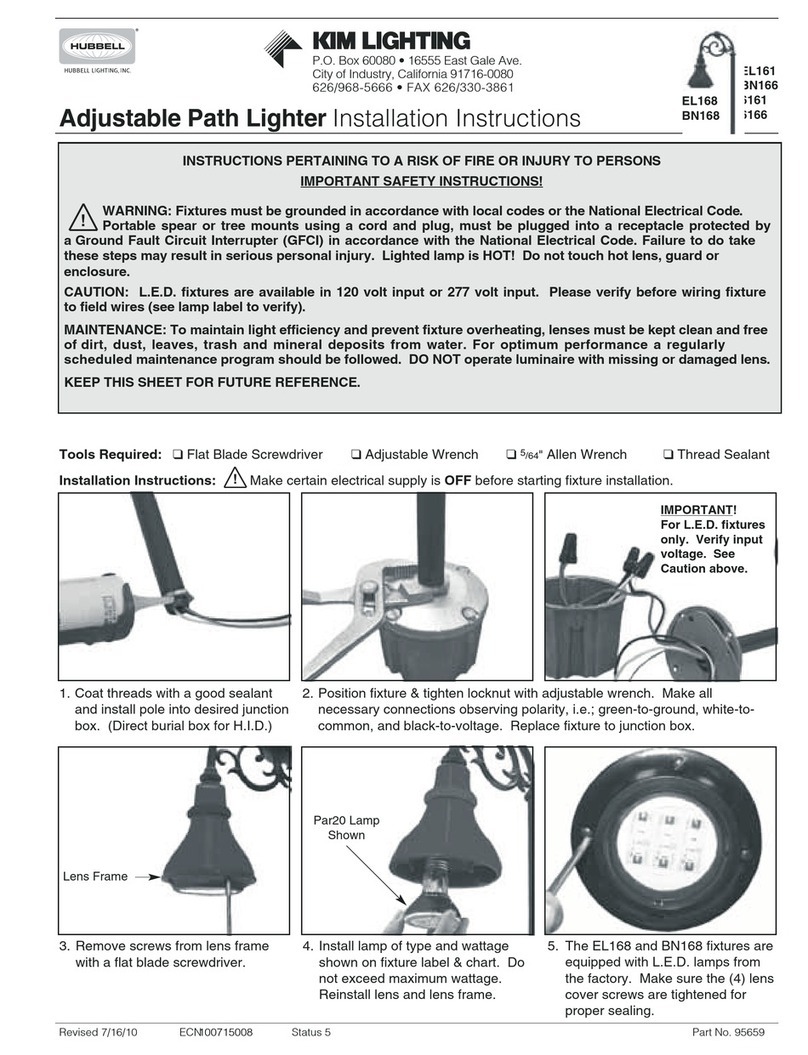
Hubbell
Hubbell Kim Lighting EL161 User manual

Hubbell
Hubbell Dual-Lite PGN Manual

Hubbell
Hubbell SLING Service manual
Hubbell
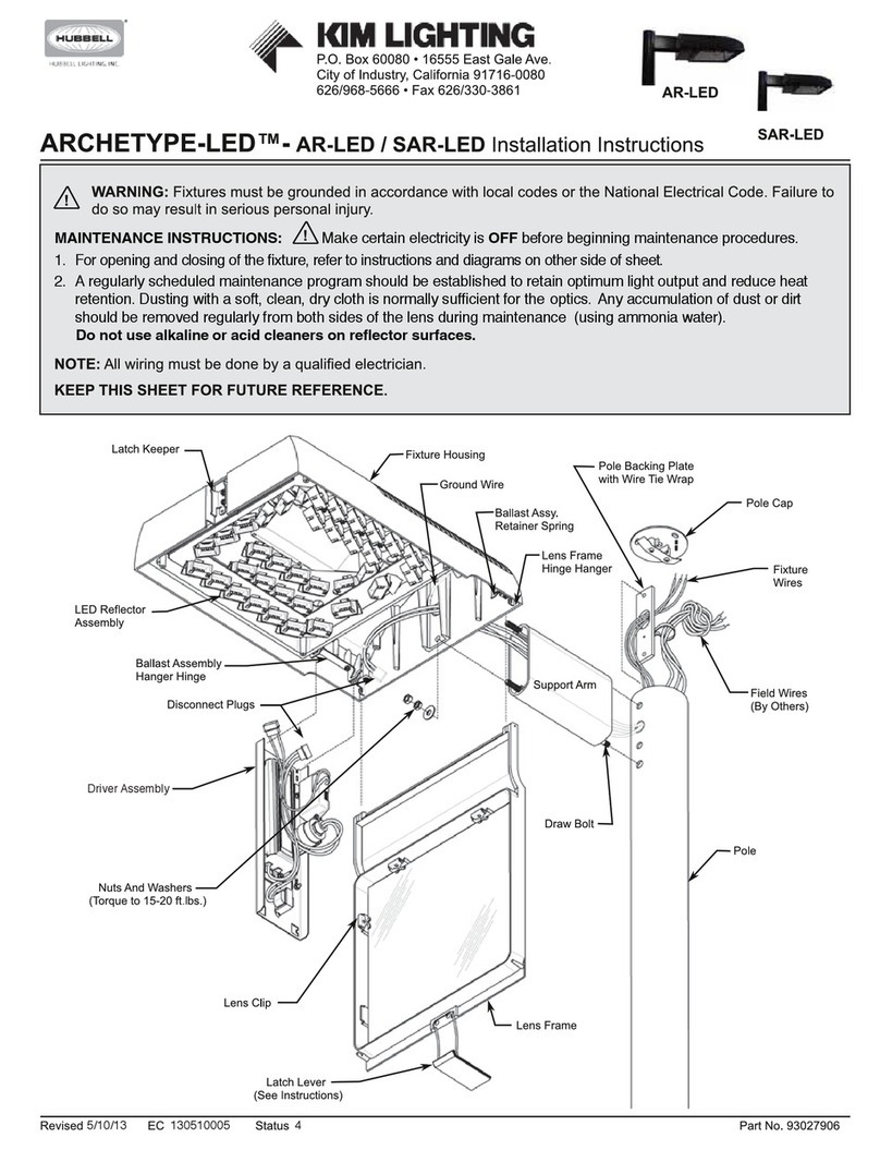
Hubbell KIM LIGHTING ARCHETYPE-LED-AR-LED User manual

Hubbell
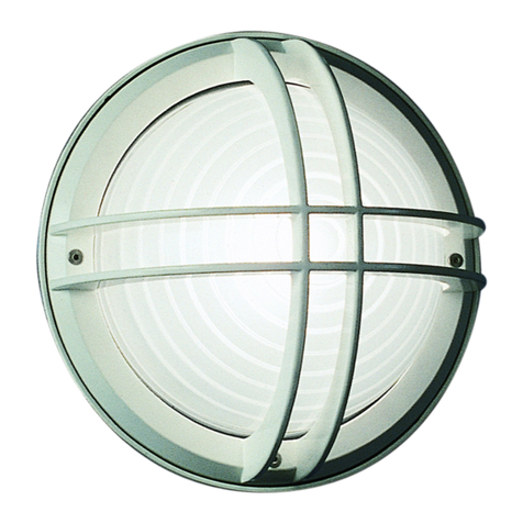
Hubbell Kim Pavilion PA7R User manual
Hubbell
Hubbell Kim Lighting Wall Forms WF30H Series User manual
Popular Outdoor Light manuals by other brands

HEPER
HEPER DOGO Side LW6048.585-US Installation & maintenance instructions

Maretti
Maretti VIBE S 14.6080.04.A quick start guide

BEGA
BEGA 84 253 Installation and technical information

HEPER
HEPER LW8034.003-US Installation & maintenance instructions

HEPER
HEPER MINIMO Installation & maintenance instructions

LIGMAN
LIGMAN BAMBOO 3 installation manual

Maretti
Maretti TUBE CUBE WALL 14.4998.04 quick start guide

Maxim Lighting
Maxim Lighting Carriage House VX 40428WGOB installation instructions

urban ambiance
urban ambiance UQL1273 installation instructions

TotalPond
TotalPond 52238 instruction manual

Donner & Blitzen
Donner & Blitzen 0-02661479-2 owner's manual

LIGMAN
LIGMAN DE-20023 installation manual
