manuals.online logo
Brands
  1. Home
  2. •
  3. Brands
  4. •
  5. Hubbell
  6. •
  7. Outdoor Light
  8. •
  9. Hubbell PERIMALITER III Service manual

Hubbell PERIMALITER III Service manual

PERIMALITER III
AND PERIMASHIELD III
INSTALLATION INSTRUCTIONS
S
EE WARNING ON CARTON
WARNINGS:
This product contains chemicals known to the state of California to cause cancer, birth
defects and/or other reproductive harm. Thoroughly wash hands after installing,
handling, cleaning, or otherwise touching this product.
Read and follow the lamp manufacturer’s warning and use information before installing
or relamping this light fixture.
Disconnect power before installing or servicing.
In
stall, operate and maintain to meet all applicable codes.
Protect all wiring connections with approved insulators (by others).
Selected fixture voltage must match supply line voltage.
GENERAL INFORMATION, JUNCTION BOX MOUNT:
Allow 6” (152.4 mm) minimum supply wire outside of junction box.
Use two 5/16” (7.925 mm) dia. min. hardware (by others) to mount fixture.
GENERAL INFORMATION, CONDUIT MOUNT:
All 12” (304.8 mm) minimum supply wire outside of conduit.
Housing conduit threads are ½-
14 NPS.
Use two 5/16”
(7.925 mm) dia. Min. hardware (by others) to mount fixture.
Use a waterproof pipe joint compound (by others) for all entries into housing.
Plug all unused entries into housing.
GENERAL INFORMATION: INSTALLATION INSTRUCTIONS
–
PHOTOCONTROL
1.
Remove raceway cover (5) and reflector (3).
2.
Loosen Ballast cover retaining screws (11) and remove Ballast cover (12).
3.
Remove ½
-14 NPS conduit plug (10) located at top of fixture.
4.
Install (PBT) photocell gasket and insert photocell from inside thru housing and
extending outward as far as possible. Secure with black plastic nut.
5.
Select ballast voltage lead which matches supply voltage and connect to red load lead
from photocell.
6.
Connect supply voltage lead to black lead from photocell.
7.
Connect Common from photocell, Common lead from ballast and Supply Common lead
together.
8.
Connect Green ground lead from fixture to Supply Ground lead.
9.
Protect all unused leads having exposed wire with approved insulators.
10.
Replace raceway cover being careful to avoid pinching wires.
11.
Replace reflector.
12.
Close refractor door and secure with two screws.
JUNCTI
ON BOX MOUNT: (See Figures 1,
2
, and 3
)
1.
Loosen lens retaining screws (1) and remove lens.
2.
Loosen reflector screws (2) and remove reflector (3).
3.
Drill or knockout two 3/8” (9.525 mm) holes at boss locations (6) on casting.
4.
Locate and drill mounting holes using template provided.
5.
Mount fixture to wall.
6.
Apply RTV around wall casting top and (2) sides.
7.
Temporarily remove rubber hole plug (7). Push wires from inside of Fixture throug
h
hole plug into junction
box
.
8.
Make wiring connections. Push wires and connections into junction box.
9.
Make sure that ends of unused voltage leads are capped and pushed inside raceway
cover
(5).
10.
Replace rubber hole plug as it was before. Do not pinch wiring.
11.
Replace reflector with large keyway hole toward bottom of fixture.
12.
Remove clear adhesive cover from reflector and discard. Tighten retaining screws.
13.
Install lamp.
14.
Replace lens and tighten retaining screws.
C
ONDUIT MOUNT: (See Figures 1,
2
, and 3
)
1.
Fo
llow Steps 1-6 listed above.
2.
Loosen raceway cover retaining screw (4) and remove raceway cover (5).
3.
Thread conduit to fixture.
4.
Make wiring connections. Place all connections in raceway area.
NOTE: For thru wiring, supply wires to be placed under reflector
for PGM 250W thru
wire, use the (3) 140oC Jumper wires and wire nuts provided. Route Jumper wire
under reflector. Make supply wire connections under raceway cover (5).
5.
Make sure that ends of unused voltage leads are capped and pushed inside raceway.
6.
Rep
lace raceway cover and tighten retaining screw.
7.
Follow Steps 10-13 listed above.
Hu
bbell Lig
ht
ing, Inc.
Do
c.
No
. 93020703
A subsidia
ry
of
Hu
bbell Incorpor
at
ed
701
Mil
lennium
Dr
ive • Greenville, SC 29607 Phone
(
86
4)
67
8-
1000
Outdoor Lighting
®
W
IRIN
G
D
IA
GR
AM
FIXTURE
GR
OUND
CO
MM
ON
VOLTAGE
GR
E
EN
/
GR
OUND
NEU
TR
AL
L
IN
E
(H
O
T)
1
APPLY
RTV SEALANT ARO
UND
CASTI
N
G TOP AN
D
(2
) SI
DES
10
F
IG
UR
E 1
F
IG
UR
A 1
F
IG
UR
E 2
F
IG
UR
A 2
F
IG
UR
E 3
F
IG
UR
A 3
LARGE
H
OLE
AG
U
JE
R
O G
RA
N
DE
GR
OS TRO
U
6
7
2
3
4
5
TH
R
U WIRI
NG (BE
HI
N
D
RE
FLE
CTO
R)
INSTALA
CIÓ
N
DE
CABLEA
DO
CO
NTÍ
N
UO
(
DET
RÁS
DEL
RE
FLE
CTO
R)
INSTALLATION À F
ILAGE
CO
NTI
NU
(
DE
R
RIÈ
RE LE RÉFLE
CTE
UR)
12
11
11
LO
AD
L
INE
COM
P
.C.
COM (
W
HT)
L
INE
(BL
K)
L
INE
V
COM
BA
LL
AST
PRIM
AR
Y
ADJU
STA
B
LE OPTICS:
(
See Fig
u
res 4
)
Lo
os
en
so
ck
et ret
aini
ng
scr
ews.
Repos
it
i
on
i
ng socket.
1.
2.
3.
Ti
ghten
i
ng socket re
ta
ini
ng screws
.
Th
e
PER
IM
ASHI
EL
D
featur
es
adj
ust
abl
e c
utoff.
T
h
e a
dj
ustm
e
nt ca
n b
e ma
d
e b
y:
F
IG
UR
E 4
F
IG
UR
A 4
MA
X
MIN
MÁX
MIN
MA
X
IM
U
M
C
UTO
FF
CO
RTE DE HAZ
MÁ
X
IM
O
CO
UPE
-
FAISCEAU
MA
X
IM
UM
MI
NI
MU
M
C
UTO
FF
CO
RTE DE HAZ
MÍ
NI
MO
CO
UPE
-
FAISCEAU
MI
NI
MUM
Industrial Lighting
Hu
bbell Lig
ht
ing, Inc.
Do
c.
No
. 93020703
A subsidia
ry
of
Hu
bbell Incorpor
at
ed
701
Mil
lennium
Dr
ive • Greenville, SC 29607 Phone
(
86
4)
67
8-
1000
Outdoor Lighting
®
SCH
MA D
E FIL
AGE
LUMI
NAI
RE
FIL D
E TE
RRE
CON
DUC
TOR
NEU
TRE
TENS
ION
VERT
/FIL
DE T
ERR
E
NEU
TRE
CON
DUC
TEU
R D'A
LIME
NTAT
ION
(SOU
S TE
NSIO
N)
ESQU
EM
A DE C
ABLE
ADO
CON
DU
CTOR
DE
ALIME
NT
ACIÓN
(BA
JO TE
NSIÓN)
NE
UT
RO
VE
R
DE/
HILO DE TIERRA
TE
NSIÓN
CON
DU
CTOR
NE
UT
RO
HILO DE TIERRA
LUMINARIA
INSTRUCCIONES DE INSTALACION
DE LOS APARATOS
PERIMALITER III
Y PERIMASHIELD III
VEA LAS PRECAUCIONES DE LA CAJA
PRECAUCIONES:
Corte la alimentación
eléctrica
antes de
llevar
a cabo la
instalación
o el
mantenimiento
Proceda a la
instalación
, la utiliz
ación y el mantenimiento de acuerdo con
todos los
códigos
oportunos.
Recubra lodas las conexiones con aislantes aprobados (no suministrados).
La
tensión
de
alimentación
deberá
ser la misma que la de la luminaria.
I
NFORMACION GENERAL
-
INSTALACION DE LA CAJA
DE
EMPALMES:
Los conductores de alimentación
deberán
sobrepasar de al menos 152.4 mm
(6 pu) la caja de
empalmes
.
Para instalar la luminaria, utilice dos piezas de ferretería (no suministradas)
de 7.925 mm (5/16 pu)
mínimo
de diámetro.
Para la utilización
de la
célula
fotoeléctrica
se necesitara un dispositivo PVL
-
PK.
INFORMACION GENERAL
-
INSTALACION DEL CONDUCTO:
Los conductores de alimentación
deberán
sobrepasar al menos 304.8 mm
(12 pu) del conducto.
Para instalar la luminaria utilice dos piezas de ferre
tería (no suministradas)
de 7.925 mm (5/16 pu) como
mínimo
de diámetro.
El conducto
del cajetin ha sido aterrajado ½-14, según el Estirado Nacional
Cilíndrico
.
Utilice un producto de impermeabilización para tubos (no suministrado) en
todas las entradas del
cajetin.
Tape todas las entradas no utilizadas del cajetin.
Para la utilización de la célula fotoeléctrica
se
necesitara
el dispositivo PVL-
PK.
INSTALACION DE LA CAJA DE EMPALMES
(Consulte las figuras 1,
2
, y 3
):
1.
Desatomille los tornillos de sujeción (1) de la lente y quite la lente.
2.
Desatomille los tomillos (2) del reflector y quite el reflector (3).
3.
Perfore o desfonde dos agujeros de 9.525 mm (3/8 pu) en los salientes (6) de
la pieza vaciada.
4.
Practique los agujeros de montaje en los sitios adecuados
sir
viéndose
de la
plantilla suministrada.
5.
Instale la luminaria en la pared.
6.
Aplique RTV entre la pared y
la parte superior así como en ambos lados de
la luminaria.
7.
Temporalmente quite el enchufe de goma (7) del agujero. Empuje
los
alambres de la caja de conex
iones por el enchufe de agujero.
8.
Efectué las conexiones. Empuje los hilos y las conexiones en al interior de la
caja de empalmes.
9.
Compruebe que los extremos de los cables de tensión no utilizados editan
cubiertos y metidos en el interior de la línea eléctrica (5).
10.
Instale de nuevo el enchufe de goma. Tener precaución de no presionar el
alambrado.
11.
Vuelva a colocar en su sitio el reflector con ayuda del agujero gordo en
loma
de pera situado cerca de la parte inferior de la luminaria.
12.
Quite el revestimiento a
dhesivo transparente del reflector y tiruelo
.
Apriete
los tornillos
sed
sujeción.
13.
Instale la
lámpara
.
14.
Vuelva a colocar la lente en su sitio y apriete los tornillos de sujeción.
INSTALACION DEL CO
NDUCTO (consulte las figuras 1,
2
, y 3):
1.
Siga las etapas 1
a 5 descritas anteriormente.
2.
Desatornille
el tomillo
de sujeción (4) de la tapa de la línea
eléctrica
y quite la
tapa (5).
3.
Alomille el conducto a la luminaria.
4.
Efectúe
las conexiones. Coloque todas las conexiones dentro de la línea
eléctrica
.
NOTA: Para l
a conexión de cableado continuo
,
coloque los conductores de
alimentación bajo el reflector.
5.
Asegúrese
de que los extremos de los cables de
tensión no utilizados
están
recubiertos y
empújelos
dentro de la
línea
eléctrica
.
6.
Vuetva
a colocar la tapa de la línea
eléctrica
en su sitio y apriete el tornillo de
sujeción.
7.
Siga las
etapas
10 a 13 descritas anteriormente.
INSTRUCTIONS D’INSTALLATION
DES APPAREILS
PERIMELITER III
ET PERIMASHIELD III
VOIR LES MISES EN GARDE SUR LA BOITE
MISES EN GARDE
:
Couper l’alimentation électrique avant d’effectuer l’installation ou l’entretien.
Installer, utiliser et effectuer l’entretien conformément aux codes locaux
pertinents.
Protéger toutes les connexions avec isolateurs approuvé
s (non fournis).
La tension d’alimentation doit correspondre à
la tension spécifiée pour le
luminaire.
INFORMATION GENERALE
-INSTALLATION A LA BOITE DE
JONCTION
:
Les conducteurs d’alimentation doivent dépass
er d’au moins 152.4 mm (6 po)
de
la boite de jonction.
Utiliser deux
vis
(non
fourni
es) de dia. 7.925 mm (5/16 po) minimum pour
installer le luminaire.
Le PVL
-PK est requis pour l’utilisation de la cell
ule
photoélectrique.
INFORMATION GENERALE
-
INSTALLATION DU CONDUIT:
Les conducteurs d’alimentation doivent dépasser d’au moins 304.
8 mm (12
po)
du
conduit.
Utiliser deux
vis
(non fou
rnis
) de dia. 7.925 mm (5/16 po
)
minimum pour
installer le luminaire.
Le conduit du boitier est
fileté
½-
14
NPS
.
Utiliser un produit d’é
tanchéité pour tuyaux (non fourn
is
) pour toutes les
entrées du boitie
r.
Boucher toutes les entrées inutilisées du boitier.
Le PVL
-PK est requis pour l’utilisation de la cell
ule
photoélectrique.
INSTALLATION A LA BOITE DE JONCTION (consulter les figures 1,
2, et 3)
:
1.
Desserrer la vis de retenue (1) de la lentille et enlever la lentille.
2.
Desserrer la vis (2) du réflecteur et enlever le réflecteur (3).
3.
Percer ou
défoncer deux trous de
9.525 mm (3/8 po) aux positions
(6)
du
boitier
.
4.
Percer des trous de montage au bon endroit en utilisant le gaba
rit
fourmi.
5.
Installer le luminaire sur le mur.
6.
Appliquer un joint d’étanchéité autour du boitier, dessus et chaque cotés.
7.
Enlever temporairement le bouchon en caoutchouc du trou (7). Pousser le
s
fils de la boite de jonction à travers le trou.
8.
Effectuer les raccordements. Pousser les fils et les raccordements a
l’intérieur de la boite de jonction.
9.
S’assurer que les fils de tension inutilisés sont capsulés et pousser derrière le
couvercle de canalisation (5).
10.
Remettre le bouchon de caoutchouc. Attention de ne pas pincer les fils.
11.
Remettr
e en place le réflecteur
et orienter le
gros trou
vers le
bas du
luminaire.
12.
Enlever le revêtement adhésif transparent du réflecteur
et
jeter. Serrer les vis
de retenue.
13.
Installer la lampe.
14.
Remettre en place la lentille et serrer les vis de retenue.
INSTA
LLATION DU CONDUIT (consulter les figures 1, 2, et 3)
:
1.
Suivre les étapes
1 a 6
énoncées plus haut.
2.
Desserrer les vis de retenue (4) du couvercle de la canalisation et enlever le
couvercle (5).
3.
Visser le conduit au luminaire.
4.
Effectuer les raccordements.
Placer tous les raccordements dans la
canalisation.
NOTE
: Po
ur le raccordement à filage continu, placer les conducteurs
d’alimentation sous le réflecteur (pour PGM 250W a filage continue). Utiliser
les 3 fils (140C) et capsules de raccordement fournis. P
ousser les fils en
dessous du réflecteur. Faire le raccordement des fils d’alimentation derrière
le couvercle de canalisation.
5.
S’assurer que les bouts des fils de tension inutilisés
sont recouverts et
pousser
derrière
le couvercle de
canalisation
(5)
.
6.
Rem
ettre en place le couvercle de la canalisation et serrer la vis de retenue.
7.
Suivre les étapes 10 a 13 indiquées plus haut.
EL
EM
ENTOS ÓPTICOS AJUSTABLES (consulte la figura 4
):
Con e
l
PER
IM
SHI
EL
D
po
dr
à e
strec
h
ar e
l h
az
l
ur
nin
os
o h
ac
ièndol
o o
sc
il
ar e
ntre 7
0
° y
90
°.
El
aj
uste s
e re
ali
za
d
e l
a s
iguie
nte form
a:
d
es
ator
nill
e l
os tor
nill
os
d
e s
uj
ec
ió
n d
e
l p
orta
l
ám
p
ar
as.
1.
ca
mb
i
e l
a p
os
ició
n d
e
l p
orta
l
ám
p
ar
as.
2.
a
pr
i
ete
l
os tor
nill
os
d
e s
uj
ec
ió
n d
e
l p
orta
l
ám
p
ar
as.
3.
MD
ÉL
ÉM
ENTS OPTIQUES RÉGLABLES (consulter la figure 4
):
L
e
PER
IM
ASHI
EL
D
perm
et de r
é
tr
é
c
ir l
e fa
i
sc
ea
u l
um
ine
ux
e
n l
e fa
i
sa
nt var
i
er e
ntre 7
0
°
et 90
°
.
Le r
è
glag
e s'ettectu
e c
omm
e s
u
it:
MD
d
esse
r
re
r
les
v
is de rete
nu
e
d
e l
a
do
uille
.
1.
chan
g
er la p
osition
d
e l
a
do
uille
.
2.
se
r
re
r
les
v
is de rete
nu
e
d
e l
a
do
uille
.
3.
Industrial Lighting
MOUNTING HOLES
AGUJEROS DE MONTAJE
TROU DE MONTAGE
5" (127.0 mm) 5" (127.0 mm)
CENTERLINE OF FIXTURE
LÍNEA CENTRAL DE LA LUMINARIA
LIGNE CENTRALE DU LUMINAIRE
CENTERLINE OF FIXTURE
LÍNEA CENTRAL DE LA LUMINARIA
LIGNE CENTRALE DU LUMINAIRE
ACCESS HOLE
AGUJERO DE ACCESO
TROU D'ACCÈS
Template for PVL / PGM / PRS / PGS-A Series
PLANTILLA DE INSTALACIÓN DE LA SERIE
PVL/PRS
GABARIT D'INSTALLATION DE LA SÉRIE PVL/PRS
Outdoor Lighting
®
Hu
bbell Lig
ht
ing, Inc.
A subsidia
ry
of
Hu
bbell Incorpor
at
ed
701
Mil
lennium
Dr
ive • Greenville, SC 29607
Phone
(
86
4)
67
8-
1000
Do
c.
No
. 93020703
Industrial Lighting

This manual suits for next models

1

Other Hubbell Outdoor Light manuals

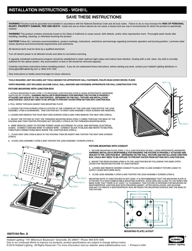
Hubbell WGH81L User manual

Hubbell

Hubbell WGH81L User manual

Hubbell Dual-Lite PGN Manual

Hubbell

Hubbell Dual-Lite PGN Manual

Hubbell RFL2 User manual

Hubbell

Hubbell RFL2 User manual

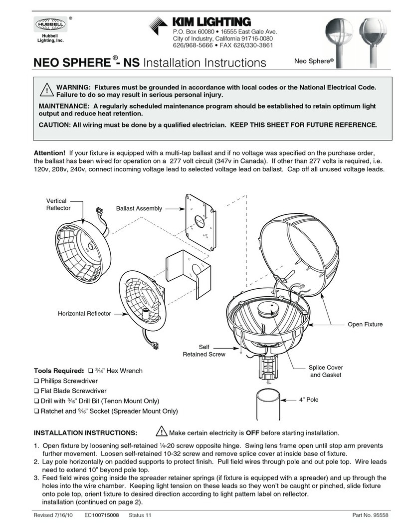
Hubbell Kim Lighting Neo Sphere NS User manual

Hubbell

Hubbell Kim Lighting Neo Sphere NS User manual

Hubbell DDL-9L1 User manual

Hubbell

Hubbell DDL-9L1 User manual

Hubbell DDL Series User manual

Hubbell

Hubbell DDL Series User manual

Hubbell LUMASQUARE User manual

Hubbell

Hubbell LUMASQUARE User manual

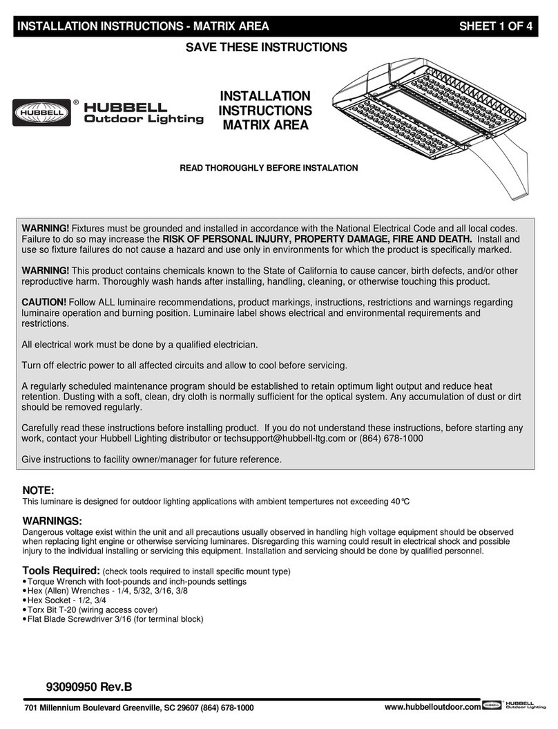
Hubbell MATRIX AREA User manual

Hubbell

Hubbell MATRIX AREA User manual

Hubbell KIM Path Pilot KLV101 User manual

Hubbell

Hubbell KIM Path Pilot KLV101 User manual

Hubbell Kim Pavilion PA7R User manual

Hubbell

Hubbell Kim Pavilion PA7R User manual

Hubbell RATIO AREA User manual

Hubbell

Hubbell RATIO AREA User manual

Hubbell KIM LIGHTING VSBC User manual

Hubbell

Hubbell KIM LIGHTING VSBC User manual

Hubbell AIRO User manual

Hubbell

Hubbell AIRO User manual

Hubbell Killark KFLX Series Instruction Manual

Hubbell

Hubbell Killark KFLX Series Instruction Manual

Hubbell KIM LIGHTINING C24 User manual

Hubbell

Hubbell KIM LIGHTINING C24 User manual

Hubbell Kim Lighting Wall Forms WF30H Series User manual

Hubbell

Hubbell Kim Lighting Wall Forms WF30H Series User manual

Hubbell Kim Lighting KLV Series User manual

Hubbell

Hubbell Kim Lighting KLV Series User manual

Hubbell FXL LED FLOOD User manual

Hubbell

Hubbell FXL LED FLOOD User manual

Hubbell KIM LIGHTING ARCHETYPE-LED-AR-LED User manual

Hubbell

Hubbell KIM LIGHTING ARCHETYPE-LED-AR-LED User manual

Hubbell Kim Lighting EL161 User manual

Hubbell

Hubbell Kim Lighting EL161 User manual

Hubbell KIM Lighting SCARAB Accent Series User manual

Hubbell

Hubbell KIM Lighting SCARAB Accent Series User manual

Hubbell SLING Service manual

Hubbell

Hubbell SLING Service manual

Hubbell VBGL-2 User manual

Hubbell

Hubbell VBGL-2 User manual

Hubbell LNC4 User manual

Hubbell

Hubbell LNC4 User manual

Popular Outdoor Light manuals by other brands

Gainsborough H738 Assembly instructions/Instructions for use

Gainsborough

Gainsborough H738 Assembly instructions/Instructions for use

Bricoman GAPP010NNNADG107 Instructions for use

Bricoman

Bricoman GAPP010NNNADG107 Instructions for use

American Gas Lamp CRAFTSMAN manual

American Gas Lamp

American Gas Lamp CRAFTSMAN manual

NOAS MIRANDA user manual

NOAS

NOAS MIRANDA user manual

LIGMAN LIGHT LINEAR PT 2 installation manual

LIGMAN

LIGMAN LIGHT LINEAR PT 2 installation manual

Alpine LED9003T user manual

Alpine

Alpine LED9003T user manual

LIGMAN LIGHTWAVE 3 installation manual

LIGMAN

LIGMAN LIGHTWAVE 3 installation manual

Sulion DARY 200764 manual

Sulion

Sulion DARY 200764 manual

Intertec Data Systems 1288438 Assembly instructions

Intertec Data Systems

Intertec Data Systems 1288438 Assembly instructions

LIGMAN ODESSA 2 installation manual

LIGMAN

LIGMAN ODESSA 2 installation manual

Integral LED PathLux ILGDA003 installation instructions

Integral LED

Integral LED PathLux ILGDA003 installation instructions

Addington Park 30812125 instructions

Addington Park

Addington Park 30812125 instructions

Sygonix Macra operating instructions

Sygonix

Sygonix Macra operating instructions

DEELAT D1151528 user manual

DEELAT

DEELAT D1151528 user manual

NOMA 052-0308-6 instruction manual

NOMA

NOMA 052-0308-6 instruction manual

Adexi WL5 manual

Adexi

Adexi WL5 manual

Dyson Lightcycle CD05 operating manual

Dyson

Dyson Lightcycle CD05 operating manual

Anslut 019700 operating instructions

Anslut

Anslut 019700 operating instructions

manuals.online logo
manuals.online logoBrands
  • About & Mission
  • Contact us
  • Privacy Policy
  • Terms and Conditions

Copyright 2025 Manuals.Online. All Rights Reserved.