2112 Fenton Logistic Park Blvd.
Fenton, MO 63026 USA
P/N KIL00921505 FORM NO. K1505 ECO6-040-20 R04/20 Page 2 of 4
Note: Due to the surge protection provided in the fixture to protect the internal electronics and LEDs, a branch
circuit with the LED fixture may false fail a megohmmeter test (sometimes referred to as a megger test). If a
megohmmeter test is required, the LED fixture should be removed from the branch circuit.
Note: Multiple fluorescent or LED fixtures attached to a single Ground Fault Circuit Interrupter (GFCI) may cause
nuisance tripping of the GFCI. Regulatory agencies allow a small amount of leakage current because of the circuitry
required to mitigate possible issues with electromagnetic compatibility(reference UL8750 and EN61347). The
summation of these leakage currents from multiple fixtures may be enough to trip a GFCI.
Note: When fitted with a polycarbonate lens, the polycarbonate lens should not be subjected to sunlight.
NOTE- For Class I, Division 1 / Class II, Division 1 / Class I, Zone 1 Hazardous Locations, use rigid conduit
or appropriate cable connectors/ glands rated for Class I, Division 1 Groups BCD
NOTE – Pour les endroits dangereux Classe I, Division 1 / Classe II, Division 1 / Classe I, Zone 1 utiliser des Conduits rigides.
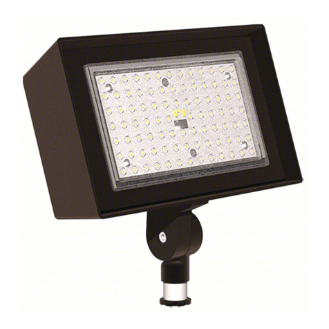
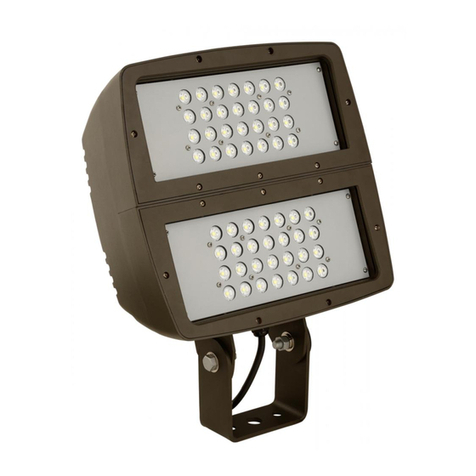
KFLX INSTALLATION INSTRUCTIONS:
1. For convenience, install the yoke bracket to the fixture before mounting the structure.
2. Loosen bolts - aim the floodlight to the desired spot.
3. Tighten both bolts securely.
4. Fasten the yoke bracket to the mounting location using ½” bolts/fasteners.
5. An “Earthquake Safety Chain” can be looped around the bosses that attach the LED heat sink to the driver box.
Pole Mounting Using Optional Knuckle:
1: Remove the center hub from the driver box. Retain the hub locking nut.
2. Attach the fixture side of the knuckle to the driver box with the four bolts provided and the hub locking nut.
3. Disassemble the knuckle and route the wires through the knuckle from the pipe side. Use stranded .425” (10.8mm)
maximum diameter cable. Attach them to the terminal block inside the light fixture. Reassemble the knuckle, leaving
enough wire below the knuckle to reach down the length of the pole.
4. Drop the wire down the pipe. Thread the pipe side of the knuckle to a 1-1/2”-11.5 NPT pipe. A pipe adapter can be
used for smaller pipes.
5. Aim the fixture appropriately and tighten the fixture in place; to both the pipe and the bolt through the knuckle.
Make sure that the circuit is de-energized at main fuse or at circuit breaker prior to installation.
NOTE IMPRORTANTE:
Mettre le circuit hors tension grace au fusible principal ou le disjoncteur.
Open the fixture by loosening the swing bolts. Using the terminal blocks supplied, run supply wire to fixture through
applicable hub. Make watertight joint using sealing fittings at appropriate hole. The included hubs are for ¾”- 14NPT. A
½-14NPT reducer is also included. The holes through the cast metal in the driver compartment are for an M25 cable
gland. To use an M25 cable gland, discard the ¾ NPT hubs.
Reattach the swing bolts. Torque the cover bolts until the cover touches the housing. Approximately 3 N-m (25 in-lbf).
Re-energized the circuit to verify the fixture is operating properly
The terminal block shown is with battery back up. Non back up
fixtures will not have the “L2” terminal. Mains wiring should be
brought in to the corresponding marked terminal. Looping
wiring can be accomplished by using the adjacent connection
port. A small screwdriver can be inserted in the slot near the
connection port to ease the force required to insert the wire.
The external ground is located next to the gland/hub opening
where the mains wires exit the fixture.
