4
WARNING - TO AVOID SERIOUS INJURY:
• Do not carry any items or attach anything to your bicycle that could hinder your vision,
hearing, or control.
• Do not ride with both hands o the handlebar.
• Do not tow or push the product.
• Do not modify the product.
• Replace worn or broken parts immediately with original equipment.
• If anything does not operate properly, discontinue use.
• DO NOT TAMPER WITH THE ELECTRICAL SYSTEM: Doing so may create a short, causing
the fuse to trip or other damage including re.
• Risk of Fire: Do not bypass fuse. Replace only with original size and type.
• The supply terminals are not to be short-circuited.
• Non-rechargeable batteries are not to be recharged.
• Batteries are to be inserted with the correct polarity.
• Rechargeable batteries are only to be charged by adults.
• The battery chargers used with the product are to be regularly examined for damage to
the cord, plug, enclosure and other parts, and in the event of such damage, they must not
be used until the damage has been repaired.
• Changes or modications to this unit not expressly approved by the party responsible for
compliance could void the user’s authority to operate the equipment.
• Do not use the vehicle in unsafe conditions such as snow, rain, loose dirt, mud sand or
ne gravel. This may result in unexpected action such as tip over and skidding. Using the
vehicle in loose dirt, mud, sand, or ne gravel may damage the electronics and gear box
inside the vehicle.
• Do not overload the vehicle. Do not drive in very hot weather, components may overheat.
Do not allow water or other liquids to come in contact with the battery or other electric
components.
• No modications to the motor to allow it to exceed a power output greater than 500W and
a speed greater than 32 km/h
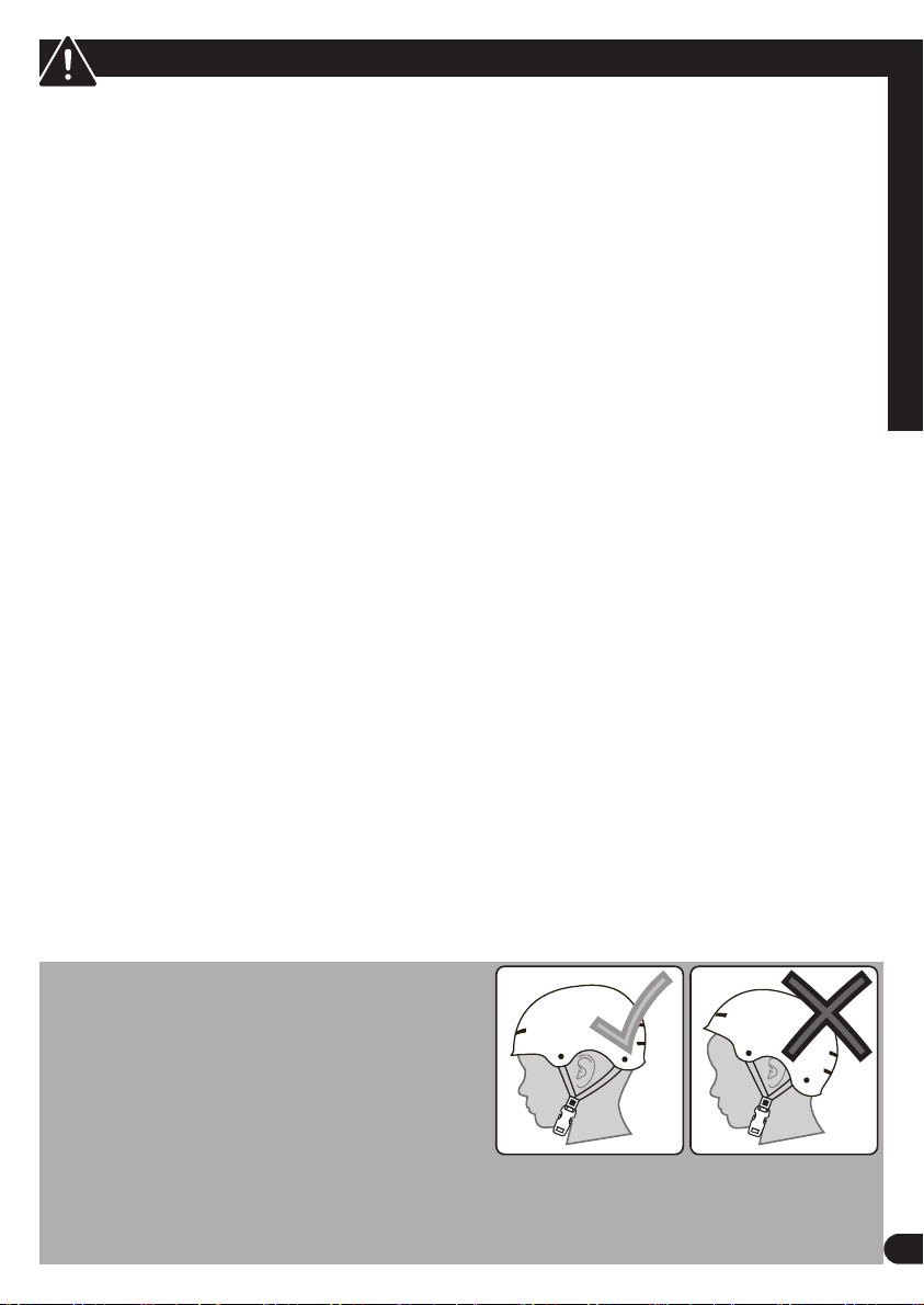
ALWAYS WEAR
YOUR HELMET
WHEN RIDING THIS
PRODUCT!
Always read the user manual that comes with your helmet to make sure it is tted and
attached properly to the wearer’s head according to the tting instructions described in the
user manual.
WARNING - TO AVOID SERIOUS INJURY:
Failure of the rider to obey the following Safety Warnings can result in serious injury or
death. Check local laws governing the use of electrical vehicles.
• ADULT RIDERS ONLY.
• SUPERVISION NECESSARY WHEN USED NEAR CHILDREN.
• DO NOT USE THE VEHICLE IN AN UNSAFE MANNER OR AT AN UNSAFE SPEED. Not
intended for jumps - this can damage the product.
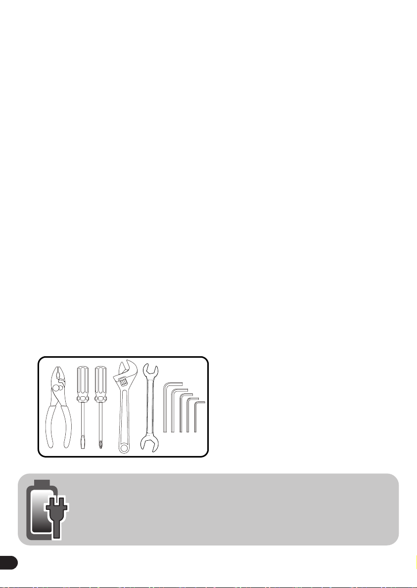
• CHOKING HAZARD: Small parts, adult assembly required.
• Before using this product, fully understand the controls and safety issues. Riders must
demonstrate the capability and skill to handle the vehicle and operate its controls to avoid
falls or collisions.
• Obey all trac regulations, signs, and signals.
• Before each ride, check that the steering system is correctly adjusted and that all connec-
tion components are rmly secured and not broken.
• While using the product, keep hands and ngers away from wheels and other moving
parts to avoid danger of pinching or entrapment.
• Riders should always wear a properly tted helmet that complies with U.S. Consumer
Product Safety Commission CPSC) Standard 16 CFR 1203 or equivalent standard for your
country.
• Always wear shoes. Gloves, knee and elbow pads recommended.
• Ride on the correct side of the road, in a single le, and in a straight line.
• There are additional hazards of using the vehicle in areas other than private grounds.
• If possible, avoid riding at night, dusk, dawn and any other time of poor visibility.
• IF YOU MUST RIDE AT NIGHT OR AT TIME OF POOR VISIBILITY:
• Use a correctly installed headlight and taillight.
• Headlights are required by all states for nighttime riding and taillights are required in
some states.
• Battery-powered lights or ashing safety lights are also recommended.
• MAKE YOURSELF MORE VISIBLE TO MOTORISTS.
• Reectors: For your own safety, do not ride the bicycle if the reectors are incorrectly
installed, damaged, or missing. Make sure the front and rear reectors are vertical. Do
not allow the visibility of the reectors to be blocked by clothing or other articles. Clean
the reectors, as necessary, with soap and a damp cloth.
• Wear light-colored or reective clothing, such as a reective vest and reective bands for
your arms and legs.
• Use reective tape on your helmet.
• USE EXTRA CAUTION IN WET WEATHER:
• Ride slowly on damp surfaces because the tires will slide more easily.
• Allow increased braking distance in wet weather.
• AVOID HAZARDS TO PREVENT LOSS OF CONTROL OR DAMAGE TO YOUR WHEELS:
• Be aware of drain grates, soft road edges, gravel or sand, pot holes or ruts, wet leaves, or
uneven paving.
• Cross railroad tracks at a right angle to prevent the loss of control.
• Do not carry any passengers.