Hughes 9300 Series Installation Guide
Contents
Hughes 9300 Series Mobile Satellite Terminal .................................................................. 1
Installation Guide................................................................................................................ 1
Introduction......................................................................................................................... 4
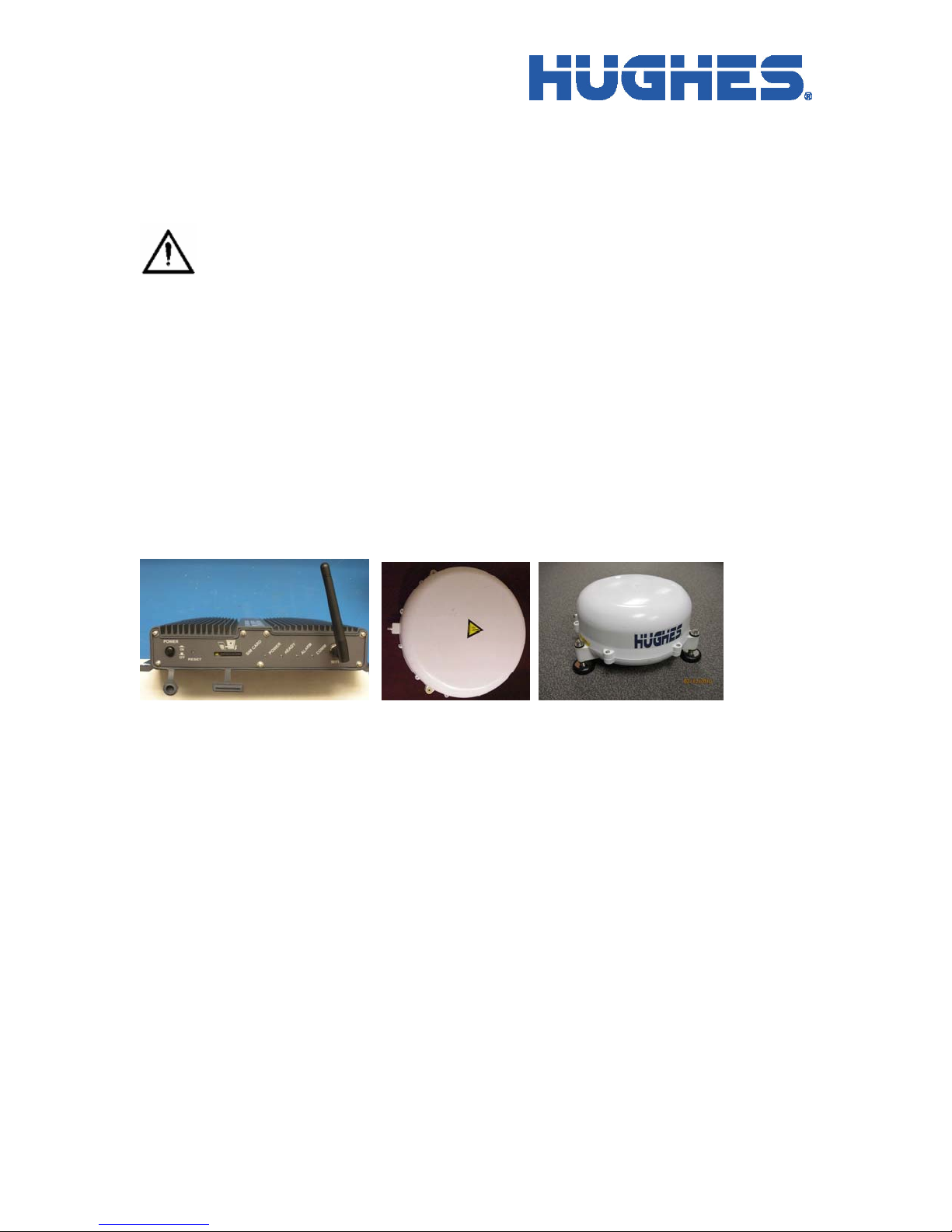
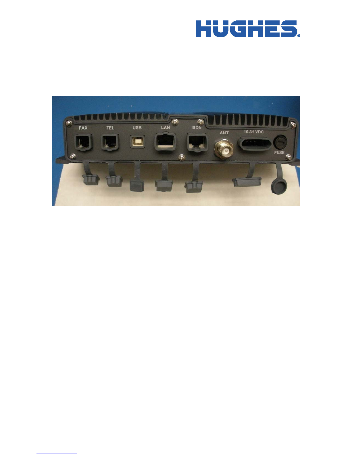
Indoor Unit (IDU)............................................................................................................... 5
Power Port....................................................................................................................... 6
Ethernet Port ................................................................................................................... 6
RJ 45 Ethernet Port with Power over Ethernet (PoE)..................................................... 6
ISDN Port........................................................................................................................ 7
RJ11 Ports ....................................................................................................................... 7
Antenna Port ................................................................................................................... 7
USB Port ......................................................................................................................... 8
WLAN Port..................................................................................................................... 8
SIM Card......................................................................................................................... 8
System Power Requirements .............................................................................................. 9
Fuse................................................................................................................................. 9
Power Cable.................................................................................................................... 9
Standard Cable Connections............................................................................................... 9
Ignition Sense (White Wire) ......................................................................................... 10
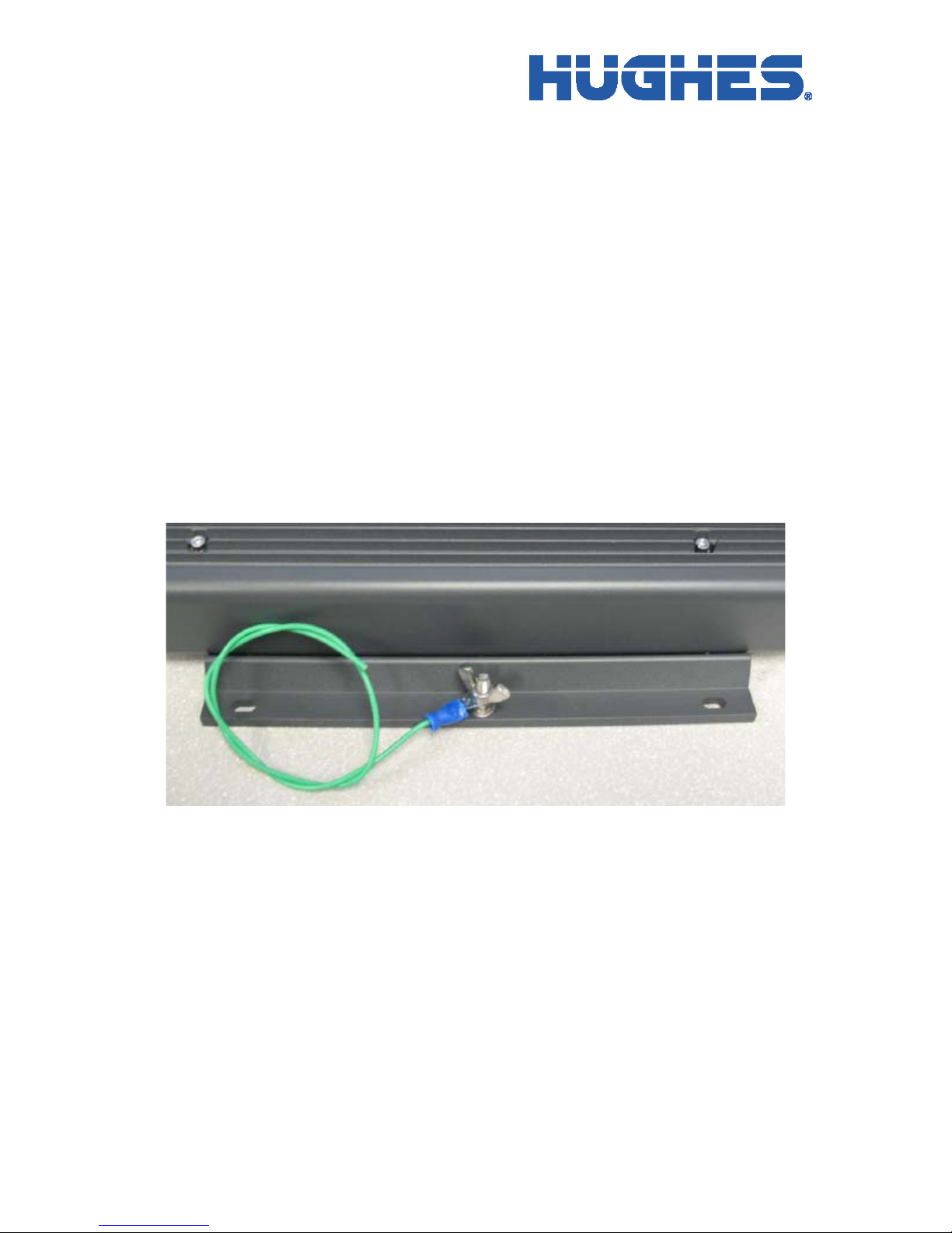
Chassis Grounding........................................................................................................ 10
Basic Installation Procedure ............................................................................................. 11
Vehicular Installation........................................................................................................ 11
Installation – General.................................................................................................... 11
Common IDU Mounting Information........................................................................... 12
The Antenna Outdoor Unit (ODU)................................................................................... 13
Antenna Cable Lengths and Types ............................................................................... 14
Installing the Antenna................................................................................................... 14
Land Mobile Antenna ....................................................................................................... 16
Magnetic Mounting (Optional)..................................................................................... 16
Magnetic Mount Installation......................................................................................... 16
Dismounting the Magnetically Mounted Antenna........................................................ 17
Permanent Mount Installation....................................................................................... 17
2