Hughes Thuraya Orion User manual

Thuraya Orion IP
Satellite Terminal
Maritime Installation Guide
3500867-0001
Revision 5
November 31Dec, 2013

Copyright © 2013 Hughes Network Systems, LLC
All rights reserved. This publication and its contents are proprietary to Hughes Network Systems,
LLC. No part of this publication may be reproduced in any form or by any means without the written
permission of Hughes Network Systems, LLC, 11717 Exploration Lane, Germantown, Maryland
20876.
Hughes Network Systems, LLC has made every effort to ensure the correctness and completeness
of the material in this document. Hughes Network Systems, LLC shall not be liable for errors
contained herein. The information in this document is subject to change without notice. Hughes
Network Systems, LLC makes no warranty of any kind with regard to this material, including, but
not limited to, the implied warranties of merchantability and fitness for a particular purpose.
Trademarks
Hughes and Hughes Network Systems are trademarks of Hughes Network Systems, LLC. All other
trademarks are the property of their respective owners.

Contents
iii
Contents
Understanding safety alert messages ..................................................................................... vii
Messages concerning personal injury......................................................................................................vii
Safety symbols.......................................................................................................................... vii
Chapter 1 Introduction.........................................................................................................9
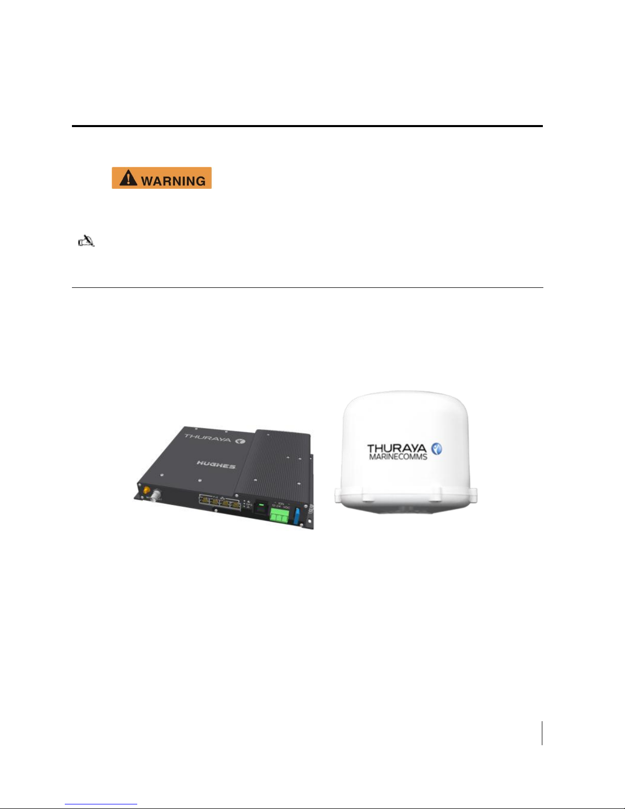
Hughes mobile satellite terminals..............................................................................................................9
Below Deck Unit (BDU) .........................................................................................................................10
Physical dimensions.............................................................................................................................10
Power port............................................................................................................................................11
Table 2. Power port pin out................................................................................................................11
Four RJ-45 Ethernet with Power over Ethernet (PoE) ports................................................................11
WLAN port..........................................................................................................................................12
Antenna port.........................................................................................................................................12
SIM card...............................................................................................................................................12
System power requirements.................................................................................................................13
Table 4. System power requirements.................................................................................................13
Fuse......................................................................................................................................................13
Chapter 2 Below Deck Unit (BDU) Install........................................................................15
Basic BDU installation procedure............................................................................................................15
Installation notes......................................................................................................................................15
BDU mounting information.....................................................................................................................16
Chapter 3 Above Deck Unit (ADU) Install.......................................................................17
Physical dimensions.................................................................................................................................17
Antenna cable lengths and types..............................................................................................................17
Antenna Location.....................................................................................................................................18
Antenna Mounting...................................................................................................................................21
Antenna Vibration....................................................................................................................................23


Figures
v
Figures
Figure 1-1. BDU (left) and ADU (right) Maritime antenna.....................................................................9
Figure 1-2. Below Decks Unit (BDU) ...................................................................................................10
Figure 1-3. Fitting the SIM card Cover..................................................................................................12
Figure 2-1. BDU - mounting dimensions in mm. ..................................................................................16
Figure 2-2 BDU Wiring Diagram.........................................................................................................16
Figure 3-1. ADU - Maritime Antenna ...................................................................................................17
Tables
Table 1. Maritime Kit Parts ...................................................................................................................10
Table 2. Power port pin out....................................................................................................................11
Table 3. RJ-45 Ethernet port pinout.......................................................................................................11
Table 4. System power requirements.....................................................................................................13


Safety
vii
Understanding safety alert messages
Safety alert messages call attention to potential safety hazards and tell you how to
avoid them. These messages are identified by the signal words WARNING or
CAUTION, as illustrated below. To avoid possible property damage, personal injury, or
in some cases possible death, read and comply with all safety alert messages.
Messages concerning
personal injury
The signal words WARNING and CAUTION indicate hazards that could result in
personal injury or in some cases death, as explained below. Each of these signal
words indicates the severity of the potential hazard.
WARNING indicates a potentially hazardous situation,
which if not avoided, could result in death or serious
injury.
CAUTION indicates a potentially hazardous situation,
which if not avoided, could result in minor or moderate
injury.
Safety symbols
The generic safety alert symbol calls attention to a potential personal injury
hazard. It appears next to the WARNING and CAUTION signal words as part of the
signal word label. Other symbols may appear next to WARNING or CAUTION to
indicate a specific type of hazard (for example, fire or electric shock).


Package materials
9
Chapter 1 Introduction
The purpose of this guide is to provide assistance to personnel installing the Thuraya
Orion IP mobile satellite terminal into a Maritime vessel.
This terminal must be installed by Authorized Service
Personnel.
Note: Damages resulting in the failure to conform to the
instructions found herein, as well as standard installation
practices, will be the responsibility of the installer.
Hughes mobile satellite terminals
The mobile satellite terminals are composed of four core component parts: the
transceiver or Below Deck Unit (BDU), the antenna or Above Deck Unit (ADU), the
power connector/cable, and a 25 meter RF cable.
Figure 1-1. BDU (left) and ADU (right) Maritime antenna

10
Package materials
The Thuraya Mobility (Maritime) kit is shipped with the following contents:
Model
Hughes part
number
Description
Thuraya Orion IP (9105)
Maritime kit
3500462-0004
Radio, Thuraya Orion IP (kit)
9506197-0001
WLAN antenna (2.4 GHz, 3 dB)
3500472-0003
Power cable with 3-pin connector
3500860-0001
SIM cover plate
9504275-0008
15 Amp, fast blow, ATO blade fuse (2 pieces)
PDF
Install Manual
PDF
User Manual
3500854-0001
Maritime Antenna Type HN321
TNC-N/25m
RF coax cable TNC-N (25 meter)
Table 1. Maritime Kit Parts
Below Deck Unit (BDU)
The BDU provides all of the TE interfaces, plus the interface for the antenna (ADU)
and manages the communications over the Thuraya network. Communication to the
ADU is provided by a single RF cable from the BDU.
Physical dimensions
BDU: Size: 46mm x 281mm x 233mm
Weight: 2.2kg
Figure 1-2. Below Decks Unit (BDU)

Package materials
11
Power port
The power port is the connection from the power supply (vessel battery or some other
12 or 24Vdc power source) to the BDU. The power cable has a DC positive power line,
a Remote Switch line and a DC negative power line.
Line type
Pin number
V+ DC power line
1
Remote Switch
2
V- DC power line
3
Table 2. Power port pin out
Four RJ-45 Ethernet with Power over Ethernet (PoE) ports
There are four RJ-45 ports with Power over Ethernet (PoE) on the BDU. The ports
supply standard PoE according to the IEEE 802.3af standard and 10/100BaseT
Ethernet. The pinout of the ports supports a direct straight-through connection to a PC
with a standard Ethernet cable. Table 3 shows the pinout of the Ethernet connector.
Pin
1
RX+
2
RX-
3
TX+
4
NC
5
NC
6
TX-
7
NC
8
NC
Table 3. RJ-45 Ethernet port pinout
Note: The +48V and -48V are supplied over the TX, RX pairs.
They are only active when an 802.3af compliant device is
plugged in. The other pairs (4, 5, 7, and 8) are unused.
All four Ethernet interfaces support up to 15 Watts of power to each PoE powered
device. The total power supplied by the PoE is limited to 30W maximum for 12 V
installations. The BDU automatically detects the class of the device plugged in and will
apply power so that the total cannot exceed these limits. If the user attempts to
connect a combination of devices that require more than this, the BDU will not power
any devices that would cause the limit to be exceeded.
Note: Class 4 (802.3at) PD devices are not supported.

12
Package materials
WLAN port
The WLAN port on the BDU is a reverse polarity SMA jack. A flexible antenna with
RP-SMA plug connector is supplied, part number HG2403RD-RSF.
To prevent blocking or attenuation of the WLAN signal, the BDU should be installed
Antenna port
The ADU (antenna) connects to the 50 Ohm female TNC connector antenna port on the
BDU by an RF cable which carries L-band RF; signaling, & DC power (42Vdc) for the
antenna.
NOTE: The antenna cable carries DC power; do not connect or disconnect the antenna
cable while the unit is powered on.
ONLY use the Thuraya Maritime Antenna Type HN321 with this BDU use of other
antennas may damage the BDU and Antenna and shall void the warranty.
SIM card
SIM Card: The BDU requires a Thuraya SIM to be installed. Insert the SIM (supplied
by your service provider) into the SIM card holder with the metal contacts facing down.
A SIM card cover is supplied as an accessory with the BDU and may be utilized if
desired. Use this to prevent accidental removal of the SIM card or if additional security
is required. Note: the following tool (not supplied) is required to fit the SIM Card
Cover: Screwdriver, Torx 8 (for a metric M2.5 screw). See Figure 1-3 for attaching the
SIM card cover.
Figure 1-3. Fitting the SIM card Cover

Package materials
13
System power requirements
There is one power connection on the BDU. This must be connected to a 12 or 24Vdc
supply. Power requirements and consumption are as follows:
Voltage Input Minimum
10V
Voltage Input Maximum
32V
Total Current for ADU and BDU
(Max. @12V)
12A
Required Fuse
15A
Table 4. System power requirements
Fuse
The fuse is a 15 Amp, fast blow, ATO blade fuse. The installed part is from Littelfuse,
part number 0257015. To replace the fuse, pull fuse out of fuse holder (pliers may be
needed to grip fuse) and press new fuse into fuse holder. Spare fuses are provided
with your Thuraya Mobility terminal.


Below Deck Unit (BDU)
15
Chapter 2 Below Deck Unit (BDU) Install
The BDU is generally located in an area accessible by the operator and protected from
water/spray. The ADU is generally located in a position to give clear line of sight to the
satellite and to avoid exposure of microwave radiation to personnel.
Basic BDU installation
procedure
The basic installation procedure is as follows:
1. Ensure that the BDU is located inside the vessel in a position that is protected
from salt water/spray/heat and attached to something structurally solid. Locations
that vibrate will degrade performance. Note: The BDU is not waterproof.
2. Determine the power cable routing from the BDU to the power source.
3. Determine an RF cable routing from the BDU to the ADU. The ADU will need to
be mounted so that it has a 360oclear view of the sky and is not within one meter
of personnel on the boat (side and top surfaces).
4. Perform the installation of the BDU per the instructions below.
Installation notes
1. Use the correct gauge of wire for both Positive and Negative wires to ensure a
minimal voltage drop under load. Suggested wire size: 14 AWG: up to 8m (26ft),
12 AWG: up to 12m (40ft), 10 AWG: up to 20m (65ft).
2. The power must be connected to a fused 12 or 24Vdc power source. The unit is
fused, but a 15A or greater fuse is required in the source to protect against shorts
in the cabling. If connecting to a circuit in a DC panel that is already in use,
ensure that the circuit can supply the unit with up to 15A for a 12V installation or
7.5A for a 24V installation.
3. Use cable ties every 300 450mm (12"-18").
4. BDU - Ground the chassis ground bolt to a nearby vessel RF ground point with a
wire 8 AWG or larger.
5. Whenever routing cable through holes drilled in metal or through bulkheads, use
grommets and RTV sealant to weatherproof all holes drilled on the outside of the
vessel.
6. Always provision the wiring into the BDU with a drip loop.
7. With the exception of the BDU-to-antenna RF cable, do not route the power
cable outside the vessel.
8. BDU MUST NOT be mounted closer than 1.0 m (3.3 ft) to a Magnetic Compass,
Fluxgate Compass or other heading device it is strongly recommended that any

16
Package materials
nearby Compass/heading device is checked for any change in deviation after
installing the terminal.
BDU mounting information
1. The BDU can be mounted in either the horizontal or vertical position.
2. Install the BDU in a protected but ventilated area. Allow at least a 1-inch space
around top and sides to provide adequate cooling.
3. Mount the terminal onto a flat surface using at least four screws or bolts (not
supplied). Use screws or bolts with a diameter between 3.5 to 4mm. Vibration-
resistant screws or lock washers should be used.
Figure 2-1. BDU - mounting dimensions in mm.
Thuraya Orion IP BDU
RSI
+
--
Vessel Ground
Chassis
Gnd Point
V+ DC Volts
Source
(fused)
V- DC Volts
Source
RSI = Remote Switch Input
Figure 2-2 BDU Wiring Diagram
Dimension BETWEEN Mounting Holes: 271mm
Dimension BETWEEN Mounting Holes:
182.5mm

The Antenna - Above Deck Unit (ADU)
17
Chapter 3 Above Deck Unit (ADU) Install
The antenna unit (ADU) is composed of the antenna element, high-power and low-
noise amplifier systems, and a mechanical tracking system housed in the radome.
The ADU is a SpaceCom HN321 3-axis antenna intended for maritime use.
Connection to the ADU is made by an N connector. The single coaxial cable carries
L-band RX and TX, power, and control information.
Physical dimensions
ADU: Size: 319.5mm x 277mm
Weight: 4kg
Figure 3-1. ADU - Maritime Antenna
Antenna cable lengths
and types
The Hughes BDU has an automatic cable calibration feature that determines the loss
of the cable. The RF cable that comes standard in the terminal kit is 25 meters long. If
a different cable is required for the installation, the end-to-end RF loss needs to be
10dB +0dB/-8dB at 1.6GHz and the cable must be 50 Ohm impedance.
Note: The installer is responsible for choosing the proper type of cable for the length
required in order to meet the loss requirement.

18
The Above Deck Unit (ADU)
Revision 1
Antenna Location
It is important for the operation and life of the Antenna and safety of personnel that the
location / mounting / fitting instructions are followed improper installation will void any
warranty.
Mounting Location:
Line-of-Sight: when locating the antenna, it is very important to ensure
there is a clear line-of-sight to the satellite for all the satellite elevation
angles in the region in which the ship will operate. The antenna rotates
360° and down to 25° for pitch and roll to allow for continuous pointing
even in heavy sea conditions. Any obstructions within this arc can cause
some signal degradation. The amount of degradation depends on the size
of the obstruction and the distance from the antenna but in general any
obstructions within 3 meters (10 feet) of the antenna should be avoided.
Obstructions less than 150 mm (6 inches) in diameter can be ignored
beyond this distance.
Radar: DO NOT install the antenna on the same plane as a Radar
Antenna the High Power Radar signal can damage or overload the
antenna front-end circuits the Antenna must be mounted above or below
the Radar beam See following tables of recommended distances
depending on the type of Radar(s) used.
Antenna Location minimum distance from RADAR
(S-Band)
Radar
Power
Output
vertical separation
Min Distance at 6
vertical separation
0-10kW
0.4 m (1.3 ft.)
0.4 m (1.3 ft.)
30kW
1.0 m (3 ft.)
0.5 m (3 ft)
50kW
2.0 m (6.6 ft)
1.0 m (3.3 ft)

The Antenna - Above Deck Unit (ADU)
19
Antenna Location minimum distance from RADAR
(X-Band)
Radar
Power
Output
vertical separation
Min Distance at 6
vertical separation
0-10kW
0.8 m (2.6 ft.)
0.4 m (1.3 ft.)
30kW
2.4 m (7.9 ft.)
1.2 m (3.9 ft)
50kW
2.0 m (6.6 ft)
2.0 m (6.6 ft)
NAVIGATIONA AIDS: see the table below for suggested co-location minimum
distances of other transmitting/receiving antennas;
Antenna Location Minimum Distance from NAV-AIDS
VHF
5.0 m (16.4 ft)
MF/HF (SSB)
5.0 m (16.4 ft)
Other L-Band Transmitters
10.0 m (32.8 ft)
GPS
Install below antenna beam -
10.0 m (32.8 ft) if in same plane
as antenna beam
NOTE: If there is other equipment installed near the Thuraya satellite terminal, it
is recommended to operate all equipment simultaneously and verify there is no co
interference.
Radiation: locate the antenna so that personnel are not exposed to microwave
radiation from the Antenna when transmitting - keep a minimum safe distance of 1
meter (39 inches) to the side and above the antenna.
Antenna Cable: the antenna cable carries DC power. Always power the BDU
down prior to connecting or disconnecting the antenna cable from either the ADU
(antenna) or the BDU.
WLAN - antenna(s) used for this transmitter must be installed to provide a
separation distance of at least 20 cm from all persons and must not be co-located
or operating in conjunction with any other antenna or transmitter

20
The Above Deck Unit (ADU)
Revision 1
Table of contents
Other Hughes Marine GPS System manuals

Hughes
Hughes BGAN 9201 Reference guide

Hughes
Hughes Strigo 4201 User manual

Hughes
Hughes BGAN 9201 User manual

Hughes
Hughes 9211 User manual

Hughes
Hughes 9201 User manual

Hughes
Hughes 9502 User manual

Hughes
Hughes 9502 User manual

Hughes
Hughes 9202 Setup guide

Hughes
Hughes 9450 Series User manual

Hughes
Hughes 9450 Series User manual