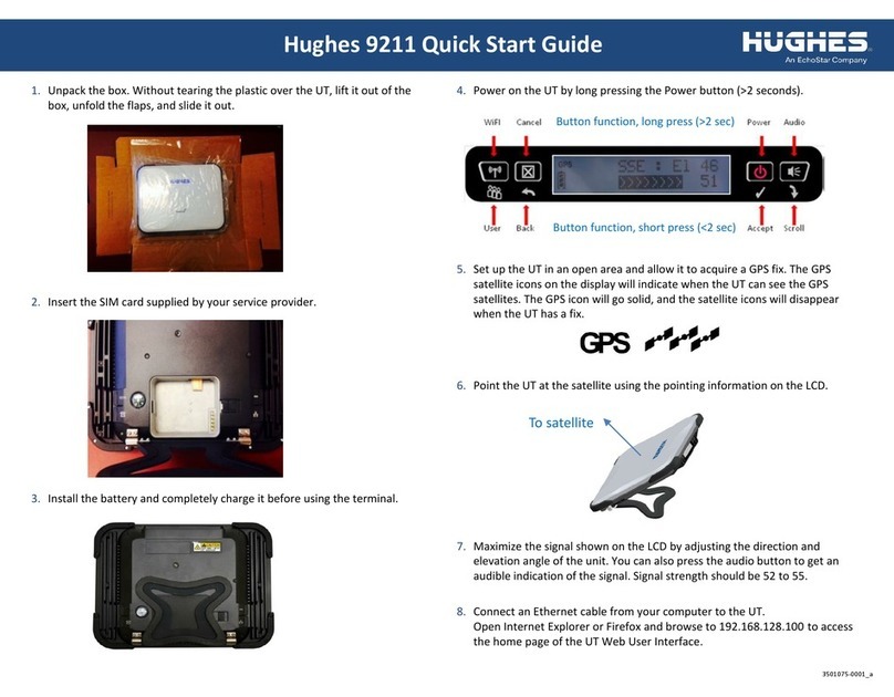
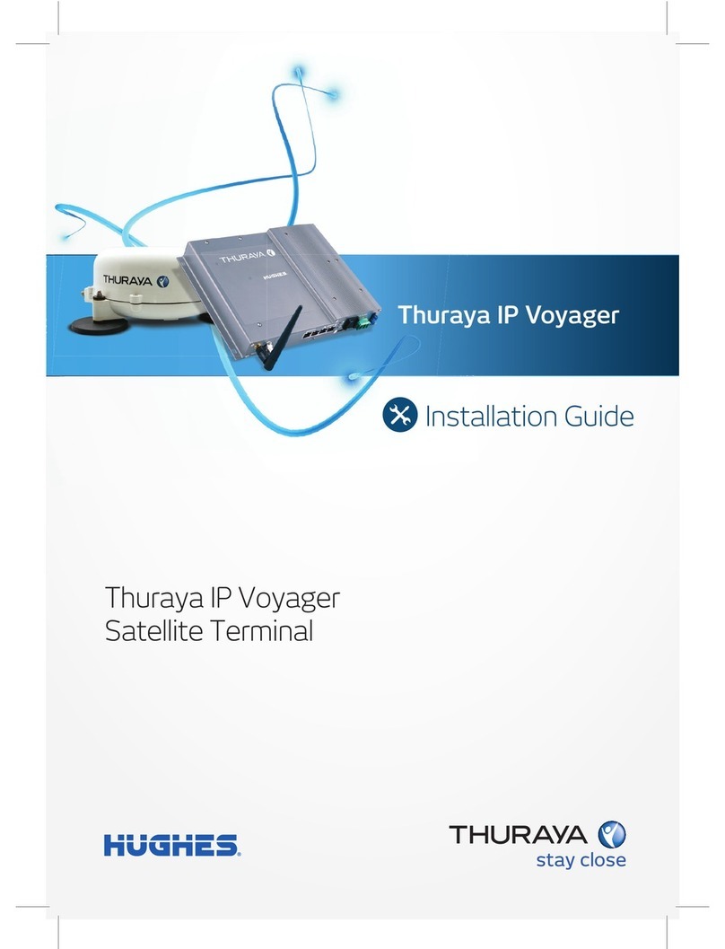
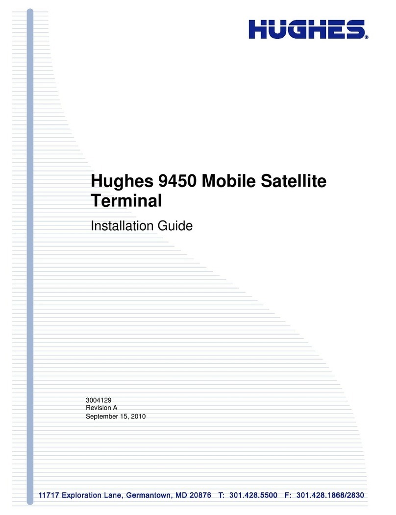
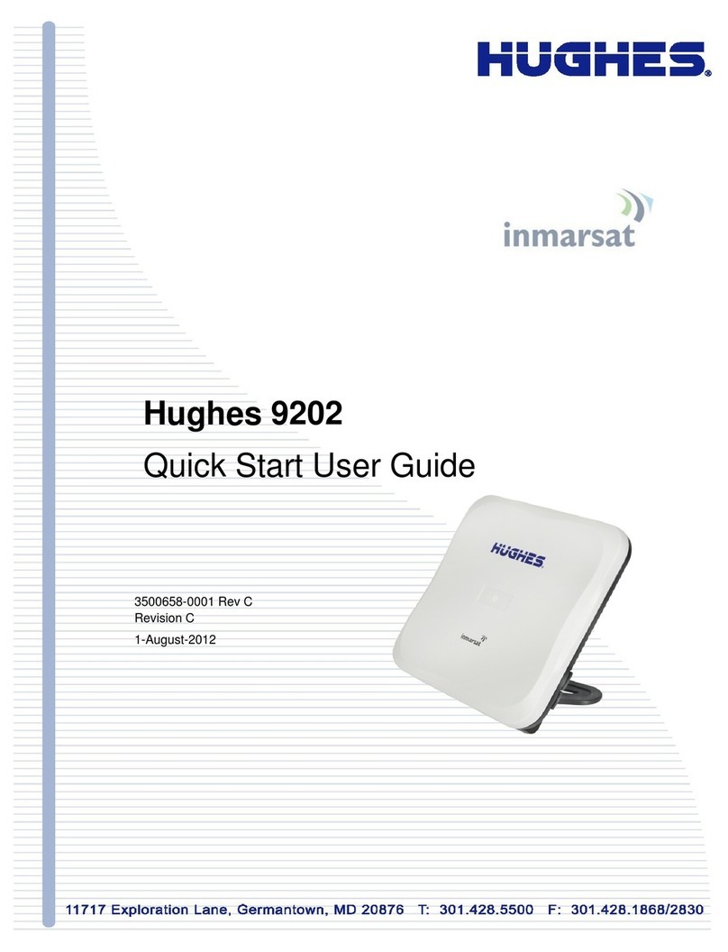
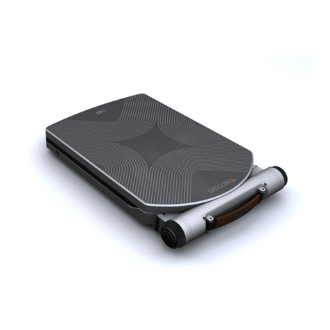
Hughes 9502 User manual

Hughes 9502 Fixed Satellite
Terminal
P/N 3500509-0001
User Guide
Document No. 3004146-0001 Rev H
18-January 2017

Copyright © 2012 - 2017 Hughes Network Systems, LLC
All rights reserved. This publication and its contents are proprietary to Hughes Network Systems,
LLC. No part of this publication may be reproduced in any form or by any means without the written
permission of Hughes Network Systems, LLC, 11717 Exploration Lane, Germantown, Maryland
20876.
Hughes Network Systems, LLC has made every effort to ensure the correctness and completeness
of the material in this document. Hughes Network Systems, LLC shall not be liable for errors
contained herein. The information in this document is subject to change without notice. Hughes
Network Systems, LLCmakes no warranty of any kind with regard to this material, including, but not
limited to, the implied warranties of merchantability and fitness for a particular purpose.
Trademarks
Hughes and Hughes Network Systems are trademarks of Hughes Network Systems, LLC. All other
trademarks are the property of their respective owners.

9502 User Guide
3004146-0001 Rev H
1
Contents
Understanding safety alert messages ........................................................................................5
Messages concerning personal injury / Messages concernant des blessures corporelles...........................5
Messages concerning property damage / Messages concernant des dommages matériels........................6
Safety symbols.............................................................................................................................7
Chapter 1 Product Description..........................................................................................13
Contents of the Hughes 9502 Kit.............................................................................................................13
Optional Mounting Accessories...............................................................................................................14
Main features of the 9502 ........................................................................................................................14
Interfaces..................................................................................................................................................15
Terminal Specifications ...........................................................................................................................17
Chapter 2 Configuration via Web UI................................................................................18
Web UI Layout ........................................................................................................................................18
Home Tab.............................................................................................................................................18
Terminal Information.......................................................................................................................18
SIM Information ..............................................................................................................................18
Troubleshooting...............................................................................................................................18
Status Bar.............................................................................................................................................20
Connections Tab ..................................................................................................................................22
Manage Contexts Page.....................................................................................................................22
Automatic Contexts..........................................................................................................................23
Manage APNs Page..........................................................................................................................25
Settings Tab .........................................................................................................................................26
General Setup...................................................................................................................................26
IP Address/DHCP Settings ..............................................................................................................27
Ethernet Port Page............................................................................................................................28
Port Forwarding Page.......................................................................................................................29
ATC Page.........................................................................................................................................30
Feature Management Page...................................................................................................................31
M2M Page............................................................................................................................................32
Ping Configuration:..........................................................................................................................32
Security Passwords ..............................................................................................................................34
Enhanced Security Settings Page.........................................................................................................35
SMS Pages...........................................................................................................................................37
Chapter 3 Operational Features........................................................................................38
LEDs........................................................................................................................................................38
Function Button .......................................................................................................................................38
Network Mode.........................................................................................................................................38
NAT Mode...........................................................................................................................................39
NAPT Mode.........................................................................................................................................39
Relay Mode..........................................................................................................................................39

2
9502 User Guide
3004146-0001 Rev H
Remote Control........................................................................................................................................40
Remote Upgrade and File Transfer..........................................................................................................41
Security....................................................................................................................................................41
Wake on LAN (Any Packet)....................................................................................................................41
Serial Pin Power Control .........................................................................................................................42
ATC .........................................................................................................................................................42
Watchdog.................................................................................................................................................43
GNSS.......................................................................................................................................................43
Chapter 4 Installation Instructions ...................................................................................44
Inspecting the parts..................................................................................................................................44
Optional installation items:......................................................................................................................44
Determining where to install the ODU....................................................................................................44
ODU installation using the basic fix mount kit; (P/N 3004066-0002) ...............................................46
Mounting the azimuth elevation bracket..................................................................................................47
Mounting the azimuth elevation bracket onto the pole............................................................................48
Attaching RF cable to ODU.....................................................................................................................49
Attaching RF cable to the Hughes 9502 IDU ..........................................................................................50
Connecting power leads to the Hughes 9502 IDU...................................................................................51
Powering up the Hughes 9502.................................................................................................................53
Coverage Map..........................................................................................................................................54
Operation in the MEAS footprint.........................................................................................................54
Pointing the ODU ....................................................................................................................................56
LED Flow Chart.......................................................................................................................................58
Adjusting the azimuth and elevation of the ODU....................................................................................60
Exit Pointing Mode..................................................................................................................................61
Chapter 5 Lightning Protection and Safety......................................................................62
Lightning and Grounding Precautions / La foudre et la terre Précautions...............................................62
Disclaimer / Avertissement......................................................................................................................63
Chapter 6 AT Unsolicited Response Codes ......................................................................64
Chapter 7 Troubleshooting ................................................................................................66
PDP Context Activation Errors............................................................................................................67
Chapter 8 Declaration of Conformity...............................................................................68
FCC Compliance / Conformité FCC........................................................................................................69
IC Compliance / Conformité IC...............................................................................................................69
EU RoHS (Restriction of Hazardous Substances) Directive ...................................................................70
EU WEEE (Waste Electrical and Electronic Equipment) Directives......................................................70

9502 User Guide
3004146-0001 Rev H
3
Figures
FIGURE 1-1 –IDU P/N 3500563-0001 13
FIGURE 1-2 –RF CABLE WITH N TO TNC ADAPTER P/N 3500634-0001 13
FIGURE 1-3 –ODU P/N 3500564-0001 13
FIGURE 1-4 - IDU MOUNTING STRAP 14
FIGURE 1-5 - AZIMUTH/ELEVATION BRACKET 14
FIGURE 1-6 –FRONT SIDE VIEW OF IDU 16
FIGURE 1-7 –BACK SIDE VIEW OF IDU 16
FIGURE 2-1 - HOME PAGE 19
FIGURE 2-2 –ENTER POINTING 21
FIGURE 2-2 –MANAGE CONTEXTS 22
FIGURE 2-3 –AUTOMATIC CONTEXTS 23
FIGURE 2-4 –DHCP AUTOMATIC CONTEXTS 24
FIGURE 2-5 –MANAGE APNS 25
FIGURE 2-6 –GENERAL SETUP 26
FIGURE 2-7 –IP ADDRESS/DHCP SETTINGS 27
FIGURE 2-8 –ETHERNET SETTINGS 28
FIGURE 2-9 –PORT FORWARDING SETTINGS 29
FIGURE 2-10 –ATC PAGE 30
FIGURE 2-11 –FEATURE MANAGEMENT PAGE 31
FIGURE 2-12 –M2M SETUP 32
FIGURE 2-13 –SECURITY PASSWORDS 34
FIGURE 2-14 –ENHANCED SECURITY PAGE LINK 35
FIGURE 2-15 –ENHANCED SECURITY SETTINGS PAGE 35
FIGURE 2-16 –LOGIN PAGE 36
FIGURE 2-17 –SMS SEND/RECEIVE 37
FIGURE 4-1 –HOME PAGE SHOWING POINTING INFORMATION 45
FIGURE 4-2 –BASE BRACKET AND BUBBLE LEVEL 46
FIGURE 4-3 –POLE ASSEMBLY 47
FIGURE 4-4 –AZIMUTH ELEVATION BRACKET 47
FIGURE 4-5 –POLE COLLAR 48
FIGURE 4-6 –WEATHER PROOF CONNECTOR 49
FIGURE 4-7 –CONNECT CABLE TO TNC CONNECTOR ON IDU 50
FIGURE 4-8 - POWER CONNECTOR 51
FIGURE 4-9 - CONNECTING POWER LEADS 52
FIGURE 4-10 - FUNCTION BUTTON 53
FIGURE 4-11 –AREA WHERE THE UT MAY SEE 2 SATELLITES 55
FIGURE 4-12 –SIGNAL STRENGTH ON HOME PAGE 57
FIGURE 4-13 –LED FLOW CHART 58
FIGURE 4-14 - ADJUSTING ELEVATION 60
FIGURE 4-15 - ADJUSTING AZIMUTH 60
FIGURE 5-1 –9502 IDU PROTECTIVE EARTH GROUNDING 63

4
9502 User Guide
3004146-0001 Rev H
Tables
TABLE 1 –TERMINAL SPECIFICATIONS............................................................................................................17
TABLE 2 –9502 WEB UI LAYOUT.........................................................................................................................18
TABLE 3 –STATUS BAR.........................................................................................................................................20
TABLE 4 –GPS STATUS..........................................................................................................................................20
TABLE 5 –REMOTE CONTROL SMS MESSAGE COMMANDS ........................................................................40
TABLE 6 - AT UNSOLICITED RESPONSE CODES...............................................................................................65
TABLE 7 - PDP CONTEXT ACTIVATION ERRORS.............................................................................................67

9502 User Guide
3004146-0001 Rev H
5
Understanding safety alert messages
Safety alert messages call attention to potential safety hazards and
tell you how to avoid them. These messages are identified by the
signal words DANGER, WARNING, CAUTION, or NOTICE, as
illustrated below. To avoid possible property damage, personal
injury or in some cases possible death read and comply with all
safety alert messages.
Messages d'alerte de sécurité attirent l'attention sur les
dangers potentiels et de vous dire comment les éviter. Ces
messages sont identifiés par un signal mots DANGER,
AVERTISSEMENT, ATTENTION, ou avis, comme illustré ci-
dessous. Pour éviter des dommages matériels, des blessures ou
la mort dans certains cas possible de lire et de respecter tous
les messages d'alerte de sécurité.
Messages concerning
personal injury / Messages
concernant des blessures
corporelles
The signal words DANGER, WARNING, and CAUTION indicate
hazards that could result in personal injury or in some cases death,
as explained below. Each of these signal words indicates the
severity of the potential hazard.
Le signal de DANGER mots, AVERTISSEMENT et
ATTENTION indiquer les dangers qui pourraient entraîner
des blessures ou, dans certains cas la mort, comme expliqué ci-
dessous. Chacun de ces mots du signal indique la gravité du
danger potentiel.
DANGER indicates a potentially hazardous situation which, if
not avoided, will result in death or serious injury.
DANGER indique une situation potentiellement dangereuse
qui, si elle n'est pas évitée, entraînera la mort ou des
blessures graves.

6
9502 User Guide
3004146-0001 Rev H
WARNING indicates a potentially hazardous situation which, if
not avoided, could result in serious injury.
AVERTISSEMENT indique une situation potentiellement
dangereuse qui, si elle n'est pas évitée, pourrait entraîner
des blessures graves.
CAUTION indicates a potentially hazardous situation which, if
not avoided, could result in minor or moderate injury.
ATTENTION indique une situation potentiellement
dangereuse qui, si elle n'est pas évitée, pourrait entraîner
des blessures mineures ou modérées.
Messages concerning
property damage /
Messages concernant des
dommages matériels
NOTICE is used for messages concerning possible property
damage, product damage or malfunction, data loss, or other
unwanted results—but not personal injury.
AVIS est utilisée pour les messages concernant les dommages
matériels, des dommages au produit ou de dysfonctionnement,
de perte de données ou d'autres résultats indésirables, mais des
blessures non personnelle.

9502 User Guide
3004146-0001 Rev H
7
Safety symbols
The generic safety alert symbol calls attention to a
potential personal injury hazard. It appears next to the DANGER,
WARNING, and CAUTION signal words as part of the signal
word label. Other symbols may appear next to DANGER,
WARNING, or CAUTION to indicate a specific type of hazard
(for example, fire or electric shock). If other hazard symbols are
used in this document they are identified in this section.
Le symbole générique d'alerte suivant attire
l'attention sur un danger potentiel de risque de blessures. Il
apparaît à côté des mots DANGER, AVERTISSEMENT et
ATTENTION dans le cadre de l'affichage d’alerte . D'autres
symboles peuvent apparaître à côté de DANGER,
AVERTISSEMENT ou ATTENTION pour indiquer un type
spécifique de danger (par exemple, un incendie ou un choc
électrique). Si d’autres symboles de danger sont utilisés dans
ce document, ils sont décrits dans cette section.
Additional symbols / Symboles supplémentaires
Warning Potential Radio Frequency (RF)
hazard. Where you see this alert symbol and
WARNING heading, strictly follow the warning
instructions to avoid injury to eyes or other
personal injury.
Avertissement Danger possible de Fréquence
Radio (RF). A la vue de ce symbole d’alerte
et du terme AVERTISSEMENT, suivez
rigoureusement les instructions
d'avertissement afin d’éviter une blessure
aux yeux ou toute autre blessure .
Warning Where you see this alert symbol and
WARNING heading, strictly follow the warning
instructions to avoid personal injury.
Avertissement A la vue de ce symbole
d’alerte et du terme AVERTISSEMENT,
suivez rigoureusement les instructions
d'avertissement pour éviter toute blessure.

8
9502 User Guide
3004146-0001 Rev H
Danger Electric shock hazard: Where you see
this alert symbol and DANGER heading,
strictly follow the warning instructions to avoid
electric shock injury or death.
Danger Risque de choc électrique: A la vue
de ce symbole d’alerte et du terme DANGER,
suivez rigoureusement les instructions
d'avertissement pour éviter tout choc
électrique ou blessure mortelle.
Warnings for Satellite Terminal /
Avertissements pour le Terminal Satellite
Do not stand in front of the ODU (Antenna)
This device emits radio frequency energy. To
avoid injury, do not place head or other body
parts in front of the satellite ODU when system
is operational. Maintain a distance of 1 m or
more from the front of the Satellite Terminal
ODU.
Ne pas se tenir en face de l'ODU (antenne)
Cet appareil émet une énergie de fréquence
radio. Pour éviter toute blessure, ne placez
pas la tête ou toute autre partie du corps en
face de l'ODU satellite lorsque le système est
opérationnel. Maintenez une distance de 1 m
ou plus par rapport à l’ODU du terminal
satellite.
General Handle your Satellite Terminal with
care. Avoid exposing your Satellite Terminal to
extreme hot or cold temperatures outside the
range -40ºC to +75ºC.
Avoid placing the Terminal close to cigarettes,
open flames or any source of heat.
Changes or modifications to the Terminal not
expressly approved by Hughes Network
Systems will void the Warranty and could void
your authority to operate this equipment.
Only use a soft damp cloth to clean the
Terminal.

9502 User Guide
3004146-0001 Rev H
9
To avoid impaired Terminal performance, please
ensure the unit’s ODU is not damaged or
covered with foreign material like paint or
labeling.
When inserting the SIM, do not bend it or
damage the contacts in any way. When
connecting the interface cables, do not use
excessive force.
Général Manipulez votre terminal satellite
avec soin. Évitez d'exposer votre terminal
satellite à des températures extrêmement
chaudes ou froides en dehors de la plage -40 º
C à 75 º C.
Évitez de placer le terminal à proximité de la
cigarette, de flammes nues ou de toute source
de chaleur.
Les changements ou modifications apportées
au Terminal et non expressément approuvées
par Hughes Network Systems annulent la
garantie et peuvent annuler votre droit à
utiliser cet équipement.
Utilisez uniquement un chiffon doux humide
pour nettoyer le terminal.
Pour éviter toute dégradation des
performances du terminal , veuillez vous
assurer que l’ODU de l'unité n'est pas
endommagée ou recouverte d’un corps
étranger, comme de la peinture ou de
l'étiquetage.
Lorsque vous insérez la carte SIM, ne pas la
plier ni endommager les contacts en aucune
manière. Ne pas forcer lors de la connexion
des câbles d’interface.
In the vicinity of blasting work and in
explosive environments Never use the Satellite
Terminal where blasting work is in progress.
Observe all restrictions and follow any
regulations or rules. Areas with a potentially
explosive environment are often, but not always,
clearly marked.
A proximité de travaux de dynamitage et
d’environnements explosifs N'utilisez jamais
le terminal satellite près de travaux de
dynamitage en cours. Respectez toutes les

10
9502 User Guide
3004146-0001 Rev H
restrictions et suivez toutes les instructions
ou la règlementation. Les zones présentant
une atmosphère potentiellement explosive
sont généralement, mais pas toujours,
clairement signalées.
Qualified Service Do not attempt to
disassemble your Satellite Terminal. The unit
does not contain consumer-serviceable
components. Only qualified service personnel
may install or repair equipment.
Service Qualifié N'essayez pas de démonter
votre terminal satellite. L'unité ne contient
pas de composants réparables par le
consommateur. Seul le personnel qualifié
peut installer ou réparer le matériel.
Accessories Use Hughes approved accessories
only. Use of non-approved accessories may
result in loss of performance, damage to the
Satellite Terminal, fire, electric shock or injury.
Accessoires Utilisez uniquement des
accessoires approuvés par Hughes.
L’utilisation d’accessoires non approuvés
peut entraîner une dégradation de
performance, un endommagement du
terminal satellite, un incendie, une
électrocution ou des blessures.
Connecting Devices Never connect
incompatible devices to the Satellite Terminal.
When connecting the Satellite Terminal to any
other device, read the device’s User Manual for
detailed safety instructions.
Connexion de périphériques Ne jamais
connecter des périphériques incompatibles
au terminal satellite. Lors du raccordement
du terminal satellite à un autre appareil, lire
le manuel utilisateur du périphérique pour
les instructions détaillées de sécurité.
Pacemakers The various brands and models of
cardiac pacemakers available exhibit a wide range
of immunity levels to radio signals. Therefore,
people who wear a cardiac pacemaker and who
want to use a Satellite Terminal should seek the

9502 User Guide
3004146-0001 Rev H
11
advice of their cardiologist. If, as a pacemaker
user, you are still concerned about interaction with
the Satellite Terminal, we suggest you follow these
guidelines:
Maintain a distance of one meter from the
front and sides of the ODU and your
pacemaker;
Refer to your pacemaker product literature
for information on your particular device.
If you have any reason to suspect that interference
is taking place, turn off your Satellite Terminal
immediately.
Stimulateurs Cardiaques Les différentes
marques et modèles de stimulateurs cardiaques
disponibles présentent un large éventail de
niveaux d'immunité aux signaux radio. Par
conséquent, les personnes qui portent un
stimulateur cardiaque et qui veulent utiliser un
terminal satellite doivent demander l'avis de
leur cardiologue. Si, en tant qu'utilisateur de
stimulateur cardiaque, vous êtes toujours
soucieux d’une éventuelle interaction avec le
terminal satellite, nous vous suggérons de suivre
ces directives:
Maintenez un mètre de distance entre
votre stimulateur cardiaque et l'avant ou
les côtés de l'ODU;
Reportez-vous à la documentation de
votre stimulateur cardiaque pour toute
information spécifique à celui-ci.
Si vous avez un doute que des interférences se
produisent, éteignez votre terminal satellite
immédiatement.
Hearing Aids Most new models of hearing aids
are immune to radio frequency interference from
Satellite Terminals that are more than 2 meters
away. Many types of older hearing aids may be
susceptible to interference, making it very difficult

12
9502 User Guide
3004146-0001 Rev H
to use them near a Terminal. Should interference
be experienced, maintain additional separation
between you and the Satellite Terminal.
Appareils Auditifs La plupart des nouveaux
appareils auditifs sont insensibles aux
interférences dues aux fréquences radio des
terminaux satellites situés àplus de 2 m . De
nombreux modèles plus anciens peuvent être
sensibles aux interférences, ce qui les rend très
difficiles à utiliser à proximité d’un terminal.
En cas d’interférences détectées, veuillez
maintenir une distance supplémentaire entre
vous et le terminal.
Electrical Storms installation of the Satellite
Terminal during electrical storms may result in
severe personal injury or death.
Orages Electriques L’installation d’un terminal
satellite pendant un orage électrique peut
entrainer des blessures graves ou mortelles.
Protective Earth Grounding is recommended by
Hughes for both the IDU and the ODU equipment.
Please consult professional local advice for these
requirements.
Une mise à la terre de protection est
recommandée par Hughes à la fois pour l'IDU
et le matériel ODU. Veuillez consulter un
conseil professionnel local pour ces
spécifications.

9502 User Guide
3004146-0001 Rev H
13
Chapter 1 Product Description
Contents of the Hughes
9502 Kit
The Hughes 9502 Kit (P/N 3500509-0001) is a two piece design
that comes with an Indoor Unit (IDU), an Outdoor Unit (ODU) and
a 10 meter RF cable that has an N type connection at both ends and
an N to TNC adapter inside the cable bag for connection to the
IDU.
Figure 1-1 –IDU P/N 3500563-0001
Figure 1-2 –RF Cable with N to TNC adapter P/N 3500634-0001
Figure 1-3 –ODU P/N 3500564-0001

14
9502 User Guide
3004146-0001 Rev H
Optional Mounting
Accessories
The IDU can be mounted using the IDU strap (P/N 3500617-0001)
if desired. Strap will require 4 each mounting bolts either M3.5 or
6/32” (not included).
Figure 1-4 - IDU Mounting Strap
The ODU can be mounted using the Basic Fixed Mount Kit (P/N
3004066-0002) or by using the azimuth elevation bracket (P/N
1022994-0022) and an existing 1.5” diameter pole.
Figure 1-5 - Azimuth/Elevation Bracket
Main features of the 9502
The main features of the Hughes 9502 terminal are listed below:
Use of Internet Protocol (IP) via the BGAN satellite
network
Remote Management
oWeb UI interface
oSMS Control
oAT Command Control
oLog file upload
oTerminal configuration
oRemote firmware upgrade
Power Savings and Sleep Mode

9502 User Guide
3004146-0001 Rev H
15
IP Watchdog
Install Mode
XL-band ready
NAT, NAPT and Relay Modes
Auto Power ON when power is applied
Automatic PDP Context Activation (Static or DHCP)
Dedicated M2M webUI
Security
oEthernet MAC Filtering
oAdministration Password
oSMS Control password
oWhite List for SMS control
oAT Command password lock
oSIM Personalization
Phone-to-SIM
DP SIM Lock
SP SIM Lock
Interfaces
The Hughes 9502 has the following interfaces:
Ethernet connection (RJ45)
USB 1.1 connection (USB Type-B) for PC to configure
terminal (requires installation of Hughes USB driver. See
www.bgan.hughes.com )
TNC type RF connector on IDU and N-type RF connector
on the ODU
Integrated GPS receiver and L-band ODU
RS232 serial interface (DB9 male, DTE) to external
NMEA 0183 based GNSS device (e.g., GLONASS
receiver). This port cannot be used for serial data.

16
9502 User Guide
3004146-0001 Rev H
3 LED status display and a single function button
3.5 mm stereo audio jack for audio tone or voltage level
to assist in ODU pointing
USIM card slot behind SIM door
Figure 1-6 –Front side view of IDU
Figure 1-7 –Back side view of IDU

9502 User Guide
3004146-0001 Rev H
17
Terminal Specifications
Technical Specifications
Satellite TX Frequency
@ 1626.5 –1675MHz
Satellite RX Frequency
@ 1518 –1559 MHz
GPS Frequency
@ 1574.42 –1576.42 MHz
9502 Indoor Unit Weight:
1.12 Kg
9502 Indoor Unit Dimensions:
150 mm x 200 mm x 45 mm
9502 External Antenna Weight:
1.85 Kg (exclude mount and cable)
9502 External Antenna Dimensions:
385 mm x 385 mm x 33 mm
Operating Temperature
-40oC to +75oC
Storage Temperature
-55oC to +75oC
Humidity
95% RH at +40oC
9502 External Antenna Wind loading
Survival wind loading (with optional mount) up to 100 mph
9502 Indoor Unit Water and Dust
IP-40 Compliant
9502 External Antenna Water and Dust
IP-65 Compliant
Nominal Input Voltage
+12VDC / +24VDC
Data Connectivity:
RJ45 connector (Ethernet 10BaseT)
USB –Type B (USB 1.1 for configuration PC)
Other Features:
Single external BGAN Satellite and GPS antenna connection
GPS module inside Indoor Unit
3 status LEDs
Antenna pointing audio tone and voltage level indicator
through audio jack
SIM/USIM Slot (behind SIM door)
Table 1 –Terminal Specifications

18
9502 User Guide
3004146-0001 Rev H
Chapter 2 Configuration via Web UI
The UT is typically configured via the Web User Interface (UI).
Browsers that are currently supported are IE7 and newer, Mozilla,
and Safari only.
Web UI Layout
The Web User Interface (UI) can be accessed from a MAC or PC
browser by entering 192.168.128.100 as the URL (unless you
change the IP address of the UT.)
Table 2 shows the 9502 Web UI layout:
Home
Connections
Settings
M2M
Security
SMS
Home
Manage Contexts
General
M2M Setup
Security
Send/Receive SMS
Automatic
Contexts
IP Address / DHCP
Saved Drafts
Ethernet
Manage APNs
ATC Setup
Sent Messages
Features
Table 2 –9502 Web UI Layout
Home Tab
The home page includes the following fields:
Terminal Information
Model
IMEI
Software Version
SIM Information
IMSI
SIM APN
Terminal phone number
Troubleshooting
System Log
Other manuals for 9502
3
Table of contents
Other Hughes Marine GPS System manuals

Hughes
Hughes 9202M User manual

Hughes
Hughes 9211 User manual

Hughes
Hughes 9502 User manual

Hughes
Hughes IP Voyager User manual

Hughes
Hughes BGAN 9201 User manual

Hughes
Hughes 9450 Series User manual

Hughes
Hughes 9300 Series User manual

Hughes
Hughes 9202 Setup guide

Hughes
Hughes 9250 User manual

Hughes
Hughes BGAN 9201 Reference guide
Popular Marine GPS System manuals by other brands

Raymarine
Raymarine E70085 Dragonfly Operation manual

Globalstar
Globalstar GSP-2800 installation guide

Furuno
Furuno LC-90 Mark-II owner's manual

Thuraya
Thuraya IP+ Quick setup guide

SperryMarine
SperryMarine NAVIKNOT 600 SD Operation, installation and service manual

Kongsberg
Kongsberg Seapath 320 installation manual