manuals.online logo
Brands
  1. Home
  2. •
  3. Brands
  4. •
  5. Hunter
  6. •
  7. Accessories
  8. •
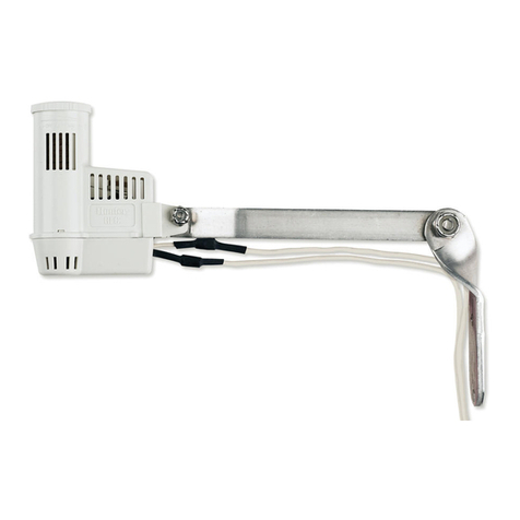
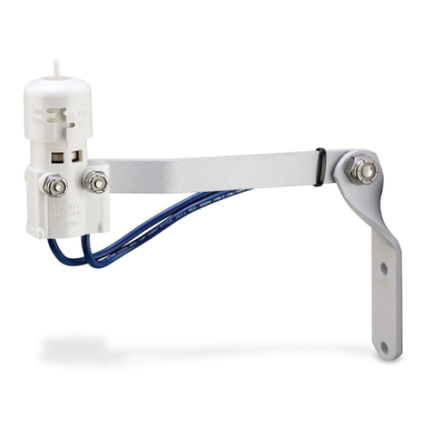
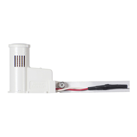
  9. Hunter MINI-CLIK User manual

Hunter MINI-CLIK User manual

a
ID
I 8
lr1
most installations, the Mini-Ciikacts as a switch to break the
circuif
tq the
..
sole11oid
valves of the irrigation system when' it has rained. This
ailovv:s
the
1.
to advance as scheduled. but keeps the
v8.1ves
from opening the water.flow,
Once the Mini-Ciik has dried sufficiently, the sWitch closes again
~o
allow for
normal operation. · · ·
The Mini-Ciik has
two
blue wiresf:Onnected to a
25·
toot extension.
For
the
Model
Mini-Ciik-C:This
rain
sensa:r unit is the
same
as
the standard
model except for the lack of an alurhinum mounting bracket and th.:
e.~dition·of
a-
1
12"
threaded cap, which allows tot the
easy
use-of electrical conduit
to·t~Jany
,_
enclose the wires. Unless local code states-Otherwise, p-lumbing grade
_PVC
prpe ·1
can be vsed as well as electrical grade
conduit
· ·
FOr
ilie
-MOdel
Mini-Ciik-HV:
This
rain sensor'unjt
·rs
desiQned
to
'be
us~d
with automatic irrigati.on systems oftwo
princip1~-de$igns:
1)
sing_l8-_$tati9n
electrical timSr (e.g., lntermatic) thatswitches power to a
pump,_.ei_th8cd[~ectly··
or through a relay;
or
2)
single-statio.:~,
electrical timer that
switch8-_$'-ptffvvar
to
-a"
solen'oid valve.
't
' - ·
··
MOUNTING
Standard
Model:
Using the screws provided,
mount
the Mini·Ciik on any surface where it will be ·
exposed to unobstructed rainfall, but not in the path of sprinkler spray.
The
switch-housing portion must be upright (as pictured), but the swivel-bracket
can·
be moved for mounting on
any
angled surface. Loosen the locknut
and
screW
before swiveling bracket,
and
then re-tighten.
For
the
Conduit
Model
Mini-Ciik-C:
The conduit acts as the
mounting support for the
uriit.Therefore, place
and
mount the conduit
to allow for the desired
sensor location
as
described in the main
instructions tor
the
standard model. Be
su,re
to support the conduit :
sufficiently along its
various lengths·.
For
the
High-VOltage:
Moder·Mini-Ciik-HV_;-.
The
mout~ting
of tliis-'Urllt
is Prim3.rily·mad.e:Qy· ..
sCfeWing the fittiq·g
~nd
·
..
into the threaded
hOles
of·
covers
to·
rectangular.
junction
bpxes
.(for_:
olltddor
use)
or
th.e
· cOvers ofr:Ouhd.junctioh
boxes cOmmOnly uSed for
·
outdOOr
spotlights. Locate
· .the jUnction box
so
that
with the Mini-Ciik
attached,
unobstructed
rainfall will hit the
'.•,
outermost sensirlg end of . _
..
,_
the unit. If a
lo_hger
reach is needed, the.:·carton':'
,flexibl_e
coflduit
pi8c~
can
be
substituted
With
a slightly
longer
piece
(up_
to
81J·J8r:~gth
with no.Sup.p6rt
or
up
to
11" with support). ' · ·
Helpful
hints
for
mounting:
. _'; _
·:-.
..
.
__
·.-
A.
When looking for a
sui_table
location
such'~f.i·Ori!~e;
side
.~lf
a bUildir'lp
Qf-PO,st:
the closer the Mini-Ciik is to the cqntro/ler;.
t!Je;
s_horter
the wire
rur..
will.be,
This
wHI
also minimize the chance for wir8
br~"8ks.
· . '
B.
The ideal location
for
mounti.rig_is not alWays the tTiosr practic8-l!cica(ion: In
the case where a compromise·rifust-exist. (such as-low· (o.catibn'on' a-Side
wall-
rather than the preferred
tJiQh
locatio~)!
·note
thcd
the'Min\~Ciik._.~ll[·s(iiJ:#PTk
as it will always receive
some
rairifa[(.~-it.just
will'not
be
as
are~ratet·in
its·
gauging as
It
could be. , · ·
~
-r;
·
•·
· •
'·
Mini-Ciik Rain Sensors
'1
Installation Instructions
~
C. As described in the "Operation" sl:!cti•Jn of this manual, "reset rate" refers to
the 8.mourrt of lirNe it takes the·Mini-Ciik to dry out sufficiently for the sprinkler
systein to be al!ow,ed
to
come back 0.1. The mounting location will affect this
rate
and
should
be
taktm into consideration should extreme conditions exist. ·
Fq,r
exaniple, mounting the Mini-Ciik on a very sunny, southern end of a
.
buildin~.,.ruay
cause the Mini-Ciik to dry out sooner than desired. Similarly,
mountii'ig
.on
the northern end of a building with constant shade may keep the
• I Mini-Clik from
drying
soor:t
enough.
_qnce the'Mini-Ciik is mounted, run the wire.to the controller, and fasten
it
every
'·few
feet with wire clips
or
stapled for best results.
If
an
extension to the wire
provided is needed, use the following table to determine the minimum wire
godge needed:
pi
the
eXt~nsion
needed is:
use: 25-50
ft.
20AWG
50-100ft. 100ft.
or
more
1BAWG 16AWG
WIRING
TO
YOUR IRRIGATION
SYSTEM
Important: The
Standard
Model
Mini-Cflik is sold and designed for hook
WP
to
/~4
Volt irrigation controllers only. For wirhig to
11
OV
or
22ov-irrigation controllers,
please consult your distributor
or
this
faCtory.
All wiring must conform to-National
. Electrical Code
Or
applicable local codeS. ' '
For
the
Model
Mini-Ciik-C:
WARNING! This unit is designed to be installed
in
conjunction with 24VAC circuits only.
Do
not
use with
'11
0 or.220VAC circuits.
For
the
Model
Mini-Ciik-HV:
WARNING! This unit must be installed by a
qualified electrician in accOrdance with National Electrical Code and applicable
-local codes. The electrical rating
of
this device is 125-250VAC at
'10.1
amps.
Do
not
let current pasS through this
d~vice
that exceeds this rating. Do not install
-,directly
in
tine with
any
pump.
Wiring
to
the
Hunter
SRC
,-~--,-------------,
The
Mini-Ciik connects
·directly
to,
the
SRC.This·
8.11ows
you to easily override
by usinQ.the RUN
(BYP~ISS
SENSOR) position
dial.
2:
·CQhnect one wire to the
RS terminal and other
to
the
cterminal (See
Figu·re 1
).
.
3.
Connect the valve common
. to the RS terminal.
Wiring
to
the
Hunter
ICC
The Mini-Ciik conriects
directly to the ICC. This
allows you to easily override
the sensor by using the
Sensor
switch on the front
panel.
1. Remove the jumper from
the
two
"SEN" terminals.
2. ROute the wires from the
rain·
sensor up through the
sS:me
conduit-operiing
used for valve witing.
\3. Connect one wire to the
terminaiiB.beled "SEN"
and the other wire to the
o;~er
"SEN" terminal (See
Figu;e 2).
Mini-Ciik
Figure
1
Mini-Ciik
Hunter
ICC
Figure
2_;,-
----'------------
--
-----.~·~····---
Hunter Industries Incorporated •1The Irrigation
lnnovatbrs
_
-r
..
-,,.~--,
. ... ,
1940 Diamond Street. San
MarcoS,
Catifornia·9~069.
U.S.A..
TEL:
(1)
7.60-744-~240
e
FA?;/(1)
7u6~7.44-74'6i
.•
Internet: wwwJ-tunterlndustrir
P/N
700802
LIT-315 6/00
>'
• • -
->
;
__
••
:-:;:.::;_:;;;:i~~_,_,:j.,'-'·~·',.
,'
v
~i.;.
•
Other Controllers
The
two
most common
situations are shown below.
For non-standard wiring
situations, please consult
your distributor or request
our "Non-standard"
wiring information packet.
A.
24 Volt Solenoid Valves
Only (No booster pump)
(See Figure
3)
With the two wires from
the Mini-Ciik at the
controller, locate the
"common ground" wire of
the solenoid valves_ If it is
connected to the common
terminal
cin
the controller,
disconnect it. Attach one
wire of the Mini-Ciik to the
"common" terminal
{usually marked "C") on
the controller. Attach the
other
Wire
of the Mini-Ciik
to the common wire
leading to the valves.
Note: The common wire
·
to
the
Valves
does
not
have
to
be interrupted
at
the controller. The
Mini-Ciik maybe wired
anywhere along the
commOn wire line.
B.
24 Volt Solenoid Valves
with Booster Pump {See
Figure 4)
Locate the common wire
to the solenoid valves
and
the common wire leading
to the coil of the relay that
starts the pump. If these
two wires are connected
to the "common"-terminal
· on the controller,
disconnect both of them.
Twist together these two
wires along with one wire
from the Mini-Ciik, and
secure with a wire nut.
Attach the other wire of
the Mini-Ciik to the
"common"terminal
on
the
' controller. Note: The pump
circuit output
must
be
24
Volts in thi$ situation. Do
not
proce~d
if
110V
c.
Special Instructions for
Mini-Ciik-HV (See Figures
5 and 6)
The
two
taped and
stripped wires are the
ones to be used when
following these accompa-
nying diagrams. The third
wire should be terminated
with a wire nut (not sup-
plied). All wire connec-
tions with the Mini-Ciik
should be made with wire
nuts and located
in
a
junction box.
Where the timer is
controlling a pump, the
relay may be inside the
Mflli-Ciik
Contr611er
i
~
L_,_,
LL,...--,=-:-----'--'-'-'+1!1:
Valves
'
Common
Wire
to
AU
Valves
'.f
,Mini-Ciik Rain Sensors
Installation Instructions
tiriier, external or non-existent. If there is
no
relay
in
the circuit, one must be
added:The "wiring for an internal
or
external relay is the same: the Mini-C!ik
breaks
the·
circuit to the coil of the relay only. Either wire of the coil may be
broken.
Operation Check
to
Verify Correct Wiring
Turn
on
one zone of the irrigation system that is visible while you are
in
reach
of the Mini-Ciik. Manually depress the spindle at
t~e
top of the Mini-Ciik until you
hear the swit-
·1
"c:!ick" off. The sprinkler zonr} sho"uld.stop instantaneously. If it
r
does
_jt.::it,
check
wiring for correctness. It is hot necessary to "wet" test the Mini-
Cii!<.,
although it will test the operation fine,
if
desired.
,,
DJUSiliMENTS .AND
OPERATION
I
Figure 3-
.!
~=========::;
l
The
Mini-Ciik can keep the irrigation system from
starting or cof1tinuing after
rainf~ll
quantities of
1/a'',
1
/4",
1f2",
3/4':
9J1
":To adjust it to the desired shut-
off
quantityi\~~-':the
cap
on
the switch housing
so that the
rr~~r~
located
in
the proper slots (see
Figure 7).
Di'd'tiot_
forcibly twist the cap·as this might
break
the
pins.
Controller
2 3
Mini-Ciik
'----4>----1,.
Solenoid
Va!yes
Une-Q.u~_(to
Pump)
Figure 4
Controller
110V
Commoh
WiretoA!I
Valves
110V
L-------•
Solenoid
Valves
Figure"t~,
Mini-Ciik-HV
' '
!
I
't
L________:____J
The time that it·takes the Mini-C!ik to reset for
norma! sprinkler operation after the rain has
stopped is determined by weather conditions (wind,
-lvent
Ring,Vent
sunlight, humidity, etc.) These conditions will
determine how fast the hygroscopic discs dry out,
and
since the turf is also experiencing the same
conditions, their respective drying rates will rou"ghly parallel each other. So when
t~e
turf needs more water, the Mini-Ciik
is
already reset to allow the sprinkler
system to go at the next scheduled cycle.
There
is an adjustment capability on the Mini-Ciik that will slow down the reset
rate.
By
turning the "vent ring" (see Figun} 7) to completely or partially
cover
the
ventilation holes, the hygroscopic discs will dry more slowly. This adjustment can
compensate- for an "overly sunny" installa{ion location, or peculiar soil conditions.
Experie~ce
will best determine the idea! vent setting.
: .'
..
The
Huilter
ICC and SRC controllers are :equipped with a built-in bypass that
allows you to override an active sensor. For controllers riot equipped with this
feature, should you desire to bypass the
~be
ration of the Mini-Ciik for any reason
{i.e., turn
on
your system even though
thE
Mini-CI!k has shut"off"
due
to
rainfall),
there are two simple ways to
do
this.
ThE
first is to add
our
Bypass Switch Box.
This mounts on or next
to
the controller, and by simply moving the switch, the
Mini~Ciik
is bypassed.The second method is to
go
to the Mini-Ciik and raise the
"cap" a couple of settings higher
or
completely remove
it
This takes the pressure
6.ff
the switch button, which allows the valve circuit to close again.
Note: Using the "manual"switch on non-Huntercontrollers typically will
not
bypass the sensor.
M.AINTEN.ANCE
·There
is no required maintenance for the unit.
The
Mini-Ciik does
not
have to be
removed or covered for "winterizing" purposes.
Troubleshooting
\;;·/,~=-
Follow these simple checks first before assuming the unit is bad and replacing
_it.
i System will
not
come on at all:
.
A.
First,
check
to see that the Mini-Ciik discs are
dry
and the switch "clicks" on
and
off freely by pressing the top of.the spindle.
B.
Next, look for breaks
in
the wire leading
to
the
Mini-Ciik and check all wire
junctions.
C. Finally, if the Mini-Ciik is drY
and
the wire leading to it is good, check the Mini-
Ctik
SWitch
by nicking the insulation of the
two
"outer" wires near the unit to
exf:-cse copper. Turn
one
sprinkler zone on, and apply a "jumper wire" across
the
tw~..
Pxrosed wires. If
the
sprinkler
now
comes on, the switch is bad. Wrap
all nicked
wirb:::
with electrical tape.
System will
not
shut off even after heavy rainfall:
A.
Check wiring for correctness (see "OPeration Check to Verify Correct Wiring").
B.
Check sensitivity.setting on Mini-Ciik
.-
move cap to
more
sensitive setting.
The
Mini~Ciik
is
-an
accurate rain gauge and can
be
verified by setting up a
· "tube" tyPe rain gauge in the
same
vicinity and making periodic readings.
Is the!.rainfall actually hitting the Mini-Ciik? Check for obstructions
to
rainfall
such
as
overhiinbs, trees
or
walls.
Manufactured
under
U.S.
Patent
No.
3,808,385.
Figure
€ .
~
.'All
Mini·Ciik
~odels
are
listed
by
U!!derwriters
Laboratories,
Inc.
(UL).
Samples
of
lhese
devices
have
c----'----:C::~~:C:~t:J.'.
·(\beert
evaluated
by
ULand
meet-'l[le_"applit;:able
UL
standards
for
safety.
,,
..
.l
-~--
~··
• •
••
,_.

Other manuals for MINI-CLIK

1

Other Hunter Accessories manuals

Hunter FLOW-CLIK Operating instructions

Hunter

Hunter FLOW-CLIK Operating instructions

Hunter Hunter Accessory Table 20523 User manual

Hunter

Hunter Hunter Accessory Table 20523 User manual

Hunter Wireless Rain-Clik Original instructions

Hunter

Hunter Wireless Rain-Clik Original instructions

Hunter Rain-Clik WRC-TR User manual

Hunter

Hunter Rain-Clik WRC-TR User manual

Hunter LIT-293 User manual

Hunter

Hunter LIT-293 User manual

Hunter Solar Sync User manual

Hunter

Hunter Solar Sync User manual

Hunter Soil-Clik User manual

Hunter

Hunter Soil-Clik User manual

Hunter Wireless Rain-Clik User manual

Hunter

Hunter Wireless Rain-Clik User manual

Hunter 43758 User manual

Hunter

Hunter 43758 User manual

Hunter Wireless Rain-Clik User manual

Hunter

Hunter Wireless Rain-Clik User manual

Hunter BP-01 User manual

Hunter

Hunter BP-01 User manual

Hunter MINI-CLIK Parts list manual

Hunter

Hunter MINI-CLIK Parts list manual

Hunter Wireless Rain-Clik User manual

Hunter

Hunter Wireless Rain-Clik User manual

Hunter Wireless Rain-Clik User manual

Hunter

Hunter Wireless Rain-Clik User manual

Hunter WFS Programming manual

Hunter

Hunter WFS Programming manual

Hunter DSP700 Series User manual

Hunter

Hunter DSP700 Series User manual

Hunter WRC User manual

Hunter

Hunter WRC User manual

Hunter RAIN-CLIK WR-CLIK Operating instructions

Hunter

Hunter RAIN-CLIK WR-CLIK Operating instructions

Hunter ET SYSTEM SMARTPORT User manual

Hunter

Hunter ET SYSTEM SMARTPORT User manual

Hunter Wireless Rain-Clik User manual

Hunter

Hunter Wireless Rain-Clik User manual

Hunter WIRED RAIN-CLIK User manual

Hunter

Hunter WIRED RAIN-CLIK User manual

Hunter Light Kit Instruction manual

Hunter

Hunter Light Kit Instruction manual

Hunter FLOW-SYNC HFS Programming manual

Hunter

Hunter FLOW-SYNC HFS Programming manual

Hunter WIRED RAIN-CLIK RAIN-CLIK Parts list manual

Hunter

Hunter WIRED RAIN-CLIK RAIN-CLIK Parts list manual

Popular Accessories manuals by other brands

Waterpik WF-20 Series user manual

Waterpik

Waterpik WF-20 Series user manual

triOS TpH operating instructions

triOS

triOS TpH operating instructions

Novalynx 200-WS-02 Series user manual

Novalynx

Novalynx 200-WS-02 Series user manual

Simply Automated UPB URD manual

Simply Automated

Simply Automated UPB URD manual

Takex TX-114TR instruction manual

Takex

Takex TX-114TR instruction manual

Tri-Tronics SMARTEYE SmartDot Installation instructions manual

Tri-Tronics

Tri-Tronics SMARTEYE SmartDot Installation instructions manual

netvox R72615A user manual

netvox

netvox R72615A user manual

Honeywell RPW317 Instruction leaflet

Honeywell

Honeywell RPW317 Instruction leaflet

Lifetime 1529 owner's manual

Lifetime

Lifetime 1529 owner's manual

Goldair GFS SERIES operating instructions

Goldair

Goldair GFS SERIES operating instructions

Pebble Smart Installation and training

Pebble

Pebble Smart Installation and training

Schwaiger ZHS19 manual

Schwaiger

Schwaiger ZHS19 manual

RODE Microphones AI-1 user guide

RODE Microphones

RODE Microphones AI-1 user guide

RIEKER Flex H6MM user guide

RIEKER

RIEKER Flex H6MM user guide

Hix VS-2407 owner's manual

Hix

Hix VS-2407 owner's manual

Tait T860 Series II Service manual

Tait

Tait T860 Series II Service manual

Mantra MIS100V2 instruction manual

Mantra

Mantra MIS100V2 instruction manual

Grizzly H0775 instruction sheet

Grizzly

Grizzly H0775 instruction sheet

manuals.online logo
manuals.online logoBrands
  • About & Mission
  • Contact us
  • Privacy Policy
  • Terms and Conditions

Copyright 2025 Manuals.Online. All Rights Reserved.