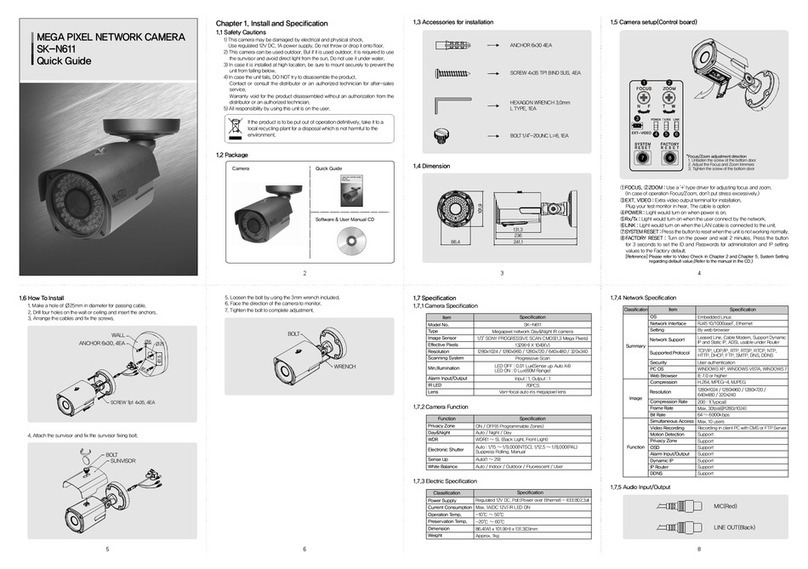
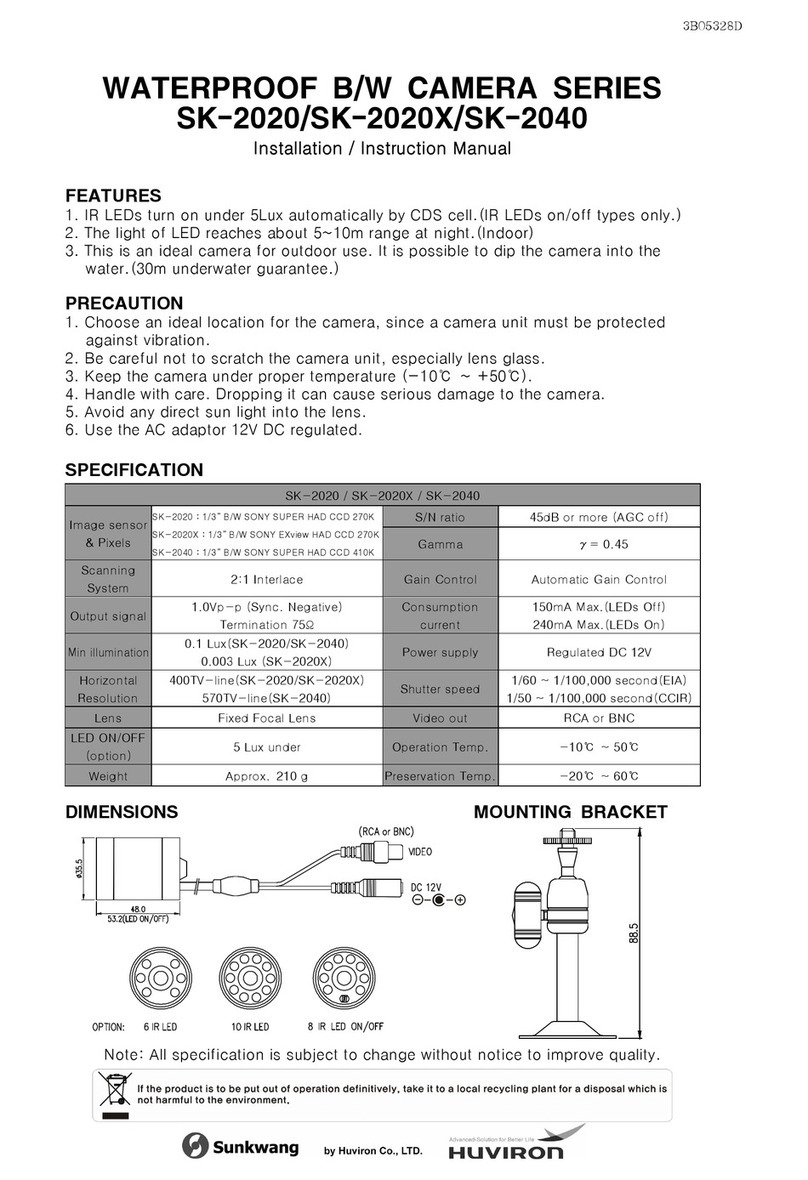
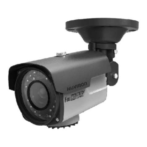
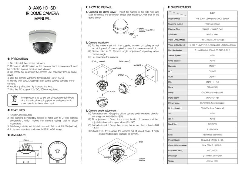
Huviron SK-P464D/M556AI User manual

English
3B26142A
SK-P464D/M556AI
D-WDR / 700TVL Pipe Camera
Application : Wall & Ceiling Mount
USER GUIDE

3_ 700TVL Pipe Camera 700TVL Pipe Camera _ 4
►Table of Contents Safety information◄
Precautions
Features
What’s included & Dimension
Structure
Installation
OSD Menu setup
Trouble shooting
CAUTION
RISK OF ELECTRIC SHOCK.
DO NOT OPEN
CAUTION : TO REDUCE THE RISK OF ELECTRIC SHOCK,
DO NOT REMOVE COVER (OR BACK) NO USER
SERVICEABLE PARTS INSIDE. REFER SERVICING
TO QUALIFIED SERVICE PERSONNEL.
This symbol indicates that dangerous voltage consisting a risk of
electric shock is present within this unit.
This exclamation point symbol is intended to alert the user to the
presence of important operating and maintenance (servicing)
instructions in the literature accompanying the appliance.
Regulatory Notice
This device complies with Part 15 of the FCC Rules. Operation is subject to the
following
two conditions :
(1) This device may not cause harmful interference, and
(2) This device must accept any interference received, including interference that
may cause undesired operation.
This equipment has been tested and found to comply with the limits for a
Class A digital device, pursuant to Part 15 of the FCC Rules. These limits are
designed to provide reasonable protection against harmful interference in a
residential installation.
This equipment generates, uses, and can radiate radio frequency energy
and, if not installed and used in accordance with the instructions, may cause
harmful interference to radio communications.Operation of this equipment in
a residential area is likely to cause interference, in which case the user will be
required to correct the interference at his own expense.
If the product is to be put out of operation denitively,
take it to a local recycling plant for a disposal which
is not harmful to the environment.

5_ 700TVL Pipe Camera 700TVL Pipe Camera _ 6
►Precautions Features◄
You can install the camera outdoor.
Choose an ideal location for the camera, since a camera
unit must be protected against moisture and vibration.
Be careful not to scratch the camera unit, especially lens
or dome cover.
Use the camera within the temperature(-45℃~ 50℃).
Handle with care. Dropping it can cause serious damage.
Avoid any direct sun light toward the lens.
Use the AC adaptor 12V DC, 1A regulated.
Dual voltage product can be used 24V AC adaptor.(option)
Using 1/3" SONY Super HAD CCDⅡ(960H)
Super Supreme Resolution(700TV-Line)
Advanced D-WDR, 3D-DNR
Day & Night function
Full OSD with Multi-language
Multi function : Sense up(256X), Motion Detection, Privacy
Mask, Freeze, Flip(H/V/R), E-Zoom
40M range visible in total darkness with 40pcs of IR LEDs.
(Indoor)
3-Axis Bracket for 3D(Pan/Tilt/Roll) rotation
Extra video connector for easy installation
Coaxial communication(Pelco-C) support
RS-485 interface(Pelco-D) : option

7_ 700TVL Pipe Camera 700TVL Pipe Camera _ 8
►What’s included & Dimension Features◄
What's included
Dimension
Structure specication
MECHANICAL
Dimension 93(W) x 94.2(H) x 101.7(D)mm
Weight Approx. 900g
ENVIRONMENT
Construction Aluminum
Ingress Protection IP 68
Operating Temp -45°C ~ 50°C
Humidity 0% to 90%
FUNCTION
Protocol PELCO-D, PELCO-C (Coax Communication)
Baud Rate 2400bps
Communication RS-485 (Option)
ELECTRICAL (Power Consumption)
Power Supply Regulated 12V DC ±10%
12V DC / 24V AC Dual voltage
Current Consumption Max. 500mA (at 12V DC): LED ON
Max. 130mA (at 12V DC) LED OFF
Heater N/A
Fan N/A
CERTIFICATION
CE, FCC, ROHS Yes
CAMERA
USER GUIDE
ACCESSORY
ANCHOR 6x30, 4EA
SCREW 4x35 TP1 PAN SUS, 4EA
WRENCH 3mm L TYPE, 1EA
SUNVISOR BOLT, 1EA
Extra video output cable
for installation,
1EA(option)
WRENCH 5mm L TYPE, 1EA

9_ 700TVL Pipe Camera 700TVL Pipe Camera _ 10
►Installation Installation◄
HOW TO INSTALL
1. Make a hole of Ø25mm in diameter for passing cable.
2. Drill four holes on the wall or ceiling and insert the anchors.
3. Arrange the cables and x the screws.
ANCHOR 6x30, 4 EA
SCREW Tp1 4x35, 4 E A
BOLT
SUNVISOR
WRENCH 3mm
BOLT
4. Attach the sunvisor and x the sunvisor xing bolt.
* Warning : This cap must screw tightly.
5. Loosen the bolt by using the 3mm wrench included.
6. Face the direction of the camera to monitor.
7. Tighten the bolt to complete adjustment.

11 _ 700TVL Pipe Camera 700TVL Pipe Camera _ 12
►Assembly Connection◄
Assembly DC 12V
AC 24V / DC 12V
RS485
RS485
VIDEO
VIDEO
POWER
POWER
ORANGE(485A)-#28
WHITE(485B)-#28
ORANGE(485A)-#28
WHITE(485B)-#28
ANCHOR 6x30, 4 EA
SCREW Tp1 4x35, 4 E A
BOLT
SUNVISOR

13 _ 700TVL Pipe Camera 700TVL Pipe Camera _ 14
►OSD Menu Set up OSD Menu Set up◄
Main Set up OSD Menu Control and Set up
Function Setting
LENS •MANUAL •DC •VIDEO
EXPOSURE •SHUTTER •AGC •SENSE-UP
BACKLIGHT •OFF •DWDR •BLC •HSBLC
WHITE BAL •ATW •AWB •AWC •MANUAL
DAY&NIGHT •COLOR •AUTO •B/W
SMART
3DNR •VALUE •SMART NR •SMART LEVEL •SENSITIVITY
F-DNR •MANUAL •AUTO •OFF
FUNCTION
•MOTION •PRIVACY •D-EFFECT •IMAGE ADJ
•COMM ADJ •SYNC •LANGUAGE
EXIT •SAVE •RESET •CANCEL
①ENTER : Used to access the menu and conrm selection.
②UP,③DOWN : Used to move the cursor to up or down.
④LEFT,⑤RIGHT : Used to move the cursor to left or right and
change the value.
⑥FOCUS,⑦ZOOM : Use a '+' type driver for adjusting zoom
and focus. (In case of operation Focus/
Zoom, don't put stress excessively.)
⑧EXT. VIDEO : Extra video output terminal for installation.
Plug your test monitor in here. The cable is
option.
⑨DEBUG PORT : It is used for upgrading the product function
and after-sales services.
*OSD menu & Focus/Zoom adjustment direction
1. Unfasten the screw of the bottom door
2. Adjust the jog lever & Focus /Zoom trimmers
3. Tighten the screw of the bottom door
F
EXT.VIDEO
Z7
6
8
9
2
5
1
3
4
MAIN MENU
1. LENS
2. EXPOSURE
3. BACKLIGHT
4. WHITE BAL
5. DAY&NIGHT
6. SMART 3DNR
7. F-DNR
8. FUNCTION
9. EXIT
DC
OFF
ATW
COLOR
ON
OFF
SAVE
The on-screen menu is operated with the control lever on the PCB.
To call the on-screen menu, press the control lever straight downward.
The main menu is inserted:
TSelect the menu item by tilting the control lever in direction ↑or ↓.
Change an adjustment by tilting the control lever in direction ←or →.
If “ ” is indicated beside menu item or an adjusting option, It is
possible to call a submenu for further adjustments by pressing the
control lever shortly.
To return from a submenu to the superior menu level, select the menu
item RETURN and conrm by pressing down the control lever. Via the
submenu item RETURN, the menu is completely exited. Exit the main
menu via the menu item EXIT.

15 _ 700TVL Pipe Camera 700TVL Pipe Camera _ 16
LENS (MANUAL, DC, VIDEO) LENS (MANUAL, DC, VIDEO)
Function of adjusting shutter speed and AGC.
MANUAL : Select when use of Manual Iris lens or Fixed-Focal lens.
BRIGHTNESS : Brightness of the picture. (1~100)
RETURN > RET : Shift to previous menu.
(Used in all menu, refer all)
RETURN > SAVE&END : Adjust, save and out of menu.
(Used in all menu, refer all)
DC : Select when use of DC Auto-Iris lens / except the special cases,
DC is standard mode.
BRIGHTNESS : Brightness of the picture. (1~100)
IRIS SPEED : Adjust speed of lens’ iris. (1~5)
VIDEO : Select automatic lens’ iris. (VIDEO TYPE)
►Menu Set up Menu Set up◄
MAIN MENU
1. LENS
2. EXPOSURE
3. BACKLIGHT
4. WHITE BAL
5. DAY&NIGHT
6. SMART 3DNR
7. F-DNR
8. FUNCTION
9. EXIT
DC
OFF
ATW
COLOR
ON
OFF
SAVE
EXPOSURE
1. SHUTTER
2. AGC
3. SENSUP
4. RETURN
AUTO
MIDDLE
AUTO
RET
1-1. SHUTTER
AUTO : Automatic adaptation with change of amount of light (1/60 ~ 1/100000(S))
a. AUTO SHUT. MIN : 1/60(1/50) Fixed
b. AUTO SHUT. MAX : FLK,1/250,1/500,1/1000,1/2000,1/5000,1/10000,
1/20000,1/50000,1/10000
1-2. FLK : Set to FLICKERLESS mode
1-3. MANUAL : Adjust shutter manually. .(1/60(1/50)~ 1/100,000, 2X ~ X256)
1-4. 1/60(1/50) : Set to 1/60(1/50)
2. AGC (OFF, LOW, MIDDLE, HIGH) : If the illumination is poor, the video signal is
amplied accordingly by the automatic gain control (AGC). The value AGC in the
submenu EXPOSURE denes the control range. A high amplication increases
the picture brightness; however, a higher picture noise is created as well.
OFF: Deactivates the AGC function
LOW, MIDDLE, HIGH : Adjust AGC level
3. SENSE UP (AUTO, OFF) : If only a very poor illumination is available, the light
sensitivity of the camera can be increased. The shutter time is extended so that
the exposure time covers several pictures. In the line SENSE UP it is possible
to select if the sensitivity should be increased (ON) or not (OFF). If On has been
selected, adjust the factor for the exposure time (×2, ….×256)
17 _ 700TVL Pipe Camera 700TVL Pipe Camera _ 18
BACKLIGHT WHITE BAL
Function of adjusting shutter speed and AGC.
ATW : Select this when the color temperature is between 2,500°K and 9,500°K
AWB : Select when the color temperature is between 1,800K°~10,500K°
AWC->SET : To nd the optimal luminance level for the current environment, point
the camera towards a sheet of white paper and press the set button. If
the environment changed, readjust it.
MANUAL : Adjust the proportion for RED and BLUE
Strong/large sources of light coming from behind the main subject
(such as a person indoors that is in front of a window) cause the light
meter to underexpose for the main subject
►Menu Set up Menu Set up◄
MAIN MENU
1. LENS
2. EXPOSURE
3. BACKLIGHT
4. WHITE BAL
5. DAY&NIGHT
6. SMART 3DNR
7. F-DNR
8. FUNCTION
9. EXIT
MANUAL
OFF
ATW
COLOR
ON
OFF
SAVE
DWDR
1. LOW LEVEL
2. HIGH LEVEL
3. RETURN
1
RET
1
MAIN MENU
1. LENS
2. EXPOSURE
3. BACKLIGHT
4. WHITE BAL
5. DAY&NIGHT
6. SMART 3DNR
7. F-DNR
8. FUNCTION
9. EXIT
MANUAL
OFF
ATW
COLOR
ON
OFF
SAVE
DWDR
1. LOW LEVEL
2. HIGH LEVEL
3. RETURN
1
RET
1
1. OFF : Deactivates the BACKLIGHT function
2. DWDR : Rather than expensive double scan CCD, used regular CCD to perform the
WDR.
2-1. LOW LEVEL (0~15): In WDR mode, AGC in low
2-2. HIGH LEVEL (0~15) : In WDR mode, AGC in high.
2-3. RETURN
3. BLC : Back Light Compensation / User controllable mode, shown the subject clear in
anywhere.
3-1. VALUE (LOW, MIDDLE, HIGH) : Adjust the brightness.
3-2. AREA : Set up the area of using BLC
a. SINGLE : Set up the rst BLC area. (area & size adjustable)
b. DOUBLE : Set up the second BLC area. (area & size adjustable)
3-3. DEFAULT : Reset as default
4. HSBLC : High Light Compensation / Masking the highlight in the image to distinguish
the subject
4-1. GAIN (0~100) : The higher GAIN level is, the masking is covered only highlights. The
lower the GAIN level is, the masking is covered on low illuminations.
So, the lower GAIN level is, the more masking areas covered.
4-2. MODE (ALL DAY, NIGHT ONLY) : Select one
4-3. MASK-LEVEL (0~100) : Adjust the brightness on the selected area.
4-4. DEFAULT : Reset as default
4-5. M.SKIP AREA : Adjust the selected area not to get masked by HSBLC. (area, size,
on, off)

19 _ 700TVL Pipe Camera 700TVL Pipe Camera _ 20
DAY & NIGHT - Switching of day operation/ night operation SMART 3DNR (ON/OFF)
►Menu Set up Menu Set up◄
SMART 3DNR
1. VALUE
2. SMART NR
3. SMART LEVEL
4. SENSITIVITY
5. RETURN
80
ON
200
80
RET
MAIN MENU
1. LENS
2. EXPOSURE
3. BACKLIGHT
4. WHITE BAL
5. DAY&NIGHT
6. SMART 3DNR
7. F-DNR
8. FUNCTION
9. EXIT
MANUAL
OFF
ATW
COLOR
ON
OFF
SAVE
COLOR : color mode always on
AUTO : Automatic switching between day operation (color mode) and night
operation (black and-white mode) depending on the ambient brightness
DELAY (0~15) : Adjust the condition time in order to switch day and night.
D->N(AGC), N->D(AGC) : By AGC, adjust the switching point between day
and night. (0~255)
D->N(CDS), N->D(CDS) : By CDS, adjust the switching point between day
and night. (0~255)
B/W : black-and-white mode always on
BURST (ON/OFF) : Turn on or off BURST signal.
IR SMART (ON/ OFF) : When IR LED is turned on in B/W, the objects can be
clearly identied due to the function that decreases
screen saturation of objects within a short distance.
a. VALUE (0~100) : Adjust IR SMART level
b. AREA : Adjust the position and size for IR SMART
c. IR DWDR : Adjust the brightness by applying Digital Wide Dynamic Range
when IR SMART is on.
IR LED (ON/OFF) : Turn on or off IR LED at night mode.
When motion is detected, reduces the background noise, dragging and stretching of
image in a low luminance environment.
VALUE (1~200) : Adjust level of this function
SMART NR (ON/OFF) : Set the function to “ON” or “OFF”
SMART LEVEL (1~200) : Adjust the level of this function
SENSITIVITY (0~100) : Adjust the sense of this function

21 _ 700TVL Pipe Camera 700TVL Pipe Camera _ 22
►Menu Set up Menu Set up◄
F-DNR SMART 3DNR (ON/OFF)
Multiple functions can be selected.This function improves the screen view clear when it is foggy, dusty, and low light
environment.
FUNCTION
1. MOTION
2. PRIVACY
3. D-EFFECT
4. IMAGE ADJ
5. COMM ADJ
6. SYNC
7. LANGUAGE
8. RETURN
OFF
OFF
INT
ENGLISH
RET
MAIN MENU
1. LENS
2. EXPOSURE
3. BACKLIGHT
4. WHITE BAL
5. DAY&NIGHT
6. SMART 3DNR
7. F-DNR
8. FUNCTION
9. EXIT
MANUAL
OFF
ATW
COLOR
ON
OFF
SAVE
MANUAL : Adjust F-DNR manually.
LEVEL (0~31) : Adjust F-DNR level.
COLOR GAIN (0~10) : Adjust COLOR GAIN level
EDGE GAIN (0~10) : Adjust EDGE GAIN level
GAMMA (0.05~1.00) : Adjust GAMMA
AUTO : Automatic adaption with change of fogginess.
DETECT LEVEL (0~5) : Adjust the level of detect.
1. MOTION (ON/OFF) : (Mostly for use of environment where is rare movement)
If a movement noticed in camera, the alarm system delivers to monitor thru text
and/or outlines an object (as user selected).
1-1. AREA : Select for 4 areas
1-2. AREA DISPLAY : Select the position and size
1-3. VALUE : Select the level of sensitivity of subject (0~100)
1-4. MOTION VIEW : Display outlines an object or not (ON/OFF)
2. PRIVACY : To conceal picture zones which are not to be monitored, 8
independently adjustable polygons are available which may be combined as
well. To enable the masking, shortly press the control lever with the adjustment
ON. Selected. The following submenu is inserted:
2-1. AREA (1~8) : 8 areas can be selected.
2-2. AREA DISPLAY : Adjust size, location and use of matter on selected area.
2-3. COLOR : Select the colors on selected areas.
2-4. TRANSPAR (0~3) : Select the transparency on selected areas.

23 _ 700TVL Pipe Camera 700TVL Pipe Camera _ 24
►Menu Set up Menu Set up◄
FUNCTION SMART 3DNR (ON/OFF)
3. D-EFFECT : Additional digital function activated.
3-1. D-ZOOM (ON/OFF) : X1~X32 DIGITAL ZOOM can be adjustable.
a. RANGE (X1~X32) : Adjust range of digital zoom
b. PAN : Adjust left and right location on the magnied image
c. TILT : Adjust up and down location on the magnied image
3-2. SMART D-ZOOM (ON/OFF) : When motion detect, zoom in the area.
a. RANGE (X2~X5) : Adjust range of SMART D-ZOOM.
b. POSITION : Adjust the position
c. SENSITIVILITY (0~100) : Select the level of sensitivity of subject
d. TIME (0~15) : Adjust the condition time in order to catch the motion.
3-3. DIS (ON/OFF) : Improve the image stability.
3-4. FREEZE (ON/OFF) : On: To freeze steal image.
Off: Images regularly showing
3-5. MIRROR : Functions of mirror-inverted display of the picture:
(MIRROR: Mirror-inverted display at horizontal axis, V-Flip: Mirror-
inverted display at vertical axis, Rotate: Mirror-inverted display at 180°
axis, Off: No mirror-inverted display)
3-6. NEG. IMAGE (ON/OFF) : Shown the image with complementary colors
4. IMAGE ADJ : Adjust image in the screen.
4-1. SHARPNESS (0~31) : Sharpness of the picture.
4-2. MONITOR : Adjust the settings value of video appropriate to your monitor.
a. CRT : Select when used CRT monitor. Adjust details in sub menu.
b. LCD : Select when used LCD monitor. Adjust details in sub menu.
4-3. LENS SHADING : Compensates brightness of four lens’ corners.
a. LEVEL (0~60) : Adjust level
b. H-CENTER (0~255) : Adjust right and left
c. V-CENTER (0~255) : Adjust up and down.
4-4. DEFECT : Correct the defective pixel automatically when sense up
function is enable.
a.
SENSE UP (X4~X128) : When defect is on, adjust the ratio of Sense up.
b. DIFF (0~3) : When defect is on, adjust the size of Defect pixel.
c. THRESHOLD (OFF/LOW/MID/HIGH) : When defect is on, Adjust AGC
level.
d. START : Active the defect function
5. COMM ADJ : A function of related RS-485 correspondence
5-1. CAM TITLE (ON/OFF) : The ID can be displayed on screen.
5-2. PROTOCOL : RS-485 Protocol set as default, PELCO-D.
5-3. RS485 : Adjust Camera ID, ID Display, baud rate. (2,400~57,600bps)
6. SYNC (INT) : Internal Sync. type, Use DC12V.
7. LANGUAGE: Select the language.
(English, Korean, Japanese, Chinese1, Chinese2, P, Français, Español,
Italiano,Português, Dutch, German, Polish, Turkish, Hebrew, Arab)
8. EXIT
SAVE : Save & Exit
RESET : Set as a default.
CANCEL : No Save & Exit

25 _ 700TVL Pipe Camera 700TVL Pipe Camera _ 26
►Menu Set up Troubleshooting◄
SK-P464D / M556AI
SK-P464D M556AI
VIDEO
Image Sensor 1/3” COLOR SONY SUPER HAD CCD Ⅱ
Effective Pixel 976(H) X 494(V) PIXEL(NTSC), 976(H) X 582(V) PIXEL(PAL)
Scanning System 2:1 Interlace
Sync. Type Internal
Resolution Color: 700TV-Line, B/W: 800TV-Line
S/N More than 52dB or More (AGC OFF)
Video Output 1.0 Vp-p(Sync. Negative) Termination 75Ω
Min. Illumination 0.01 Lux(F/1.6), 0.0001Lux(Sense up), 0Lux(70M Range with
70pcs LED, Indoor)
LEND TYPE
Lens Vari focal auto iris lens
OPERATIONAL
On screen display Yes (16 Languages)
White Balance ATW(2,500°K~ 9,500°K)/MANUAL/AWB
Shutter Speed 1/60(1/50) ~ 1/100,000SEC sec
Sense up Auto (Selectable limit 2×~256×)/OFF
Backlight BLC / HSBLC /DWDR / OFF
AGC Low/Middle/High/Off
DNR Smart 3DNR
Motion Detection ON / OFF (4 Zone Selectable)
Privacy Masking ON / OFF (8 Zone Selectable)
Mirror OFF/MIRROR/FLIP/ROTATE
DAY & NIGHT ICR (AUTO, COLOR, B/W, EXT)
F- DNR OFF/MANUAL/AUTO(1~5)
SMART D-ZOOM ON(X2~X5)/OFF
Digital Zoom ON(X1~X32) / OFF
DIS OFF/ON
FREEZE OFF/ON
IRD-WDR OFF/ON (1~15)
DEFECT Sense up (X4~X128), DIFF(0~3), THRESHOLD(1~4)
Check if the camera and monitor’s powers are on. (Also, the voltage and polarity.)
Check if the video-out terminal of the camera and the video-in terminal of the
monitor are correctly connected.
Check if the iris of the lens is open.
Adjust Contrast and Bright level in the menu.
Check the setting of Image adjust in the menu.
Check if there is any dusts or scratches on the camera window
Adjust the camera lens either far or near to make focus.
Check the camera window if any finger prints or dusts found.
Please clean off the dusts and any unexpected stuff on the window.
Check if the MOTION DET setting is properly in the menu.
Check the setting of motion detection area.
’
Check if the video cable is connected correctly.
Check if the video cable is used properly in certain distance.
Check if the video cable is connected correctly.
Check if the video cable is used properly in certain distance.
Check if the setting of WHITE BALANCE is correct in the menu.

27 _ 700TVL Pipe Camera 700TVL Pipe Camera _ 28
►Memo Memo◄
Table of contents
Other Huviron Security Camera manuals

Huviron
Huviron SK-P461D/HD21 User manual

Huviron
Huviron SK-V109 User manual

Huviron
Huviron SK-D302IR(D)/HD21 User manual

Huviron
Huviron SK-V251IR(D) User manual

Huviron
Huviron SK-P461D/HD21 User manual

Huviron
Huviron SK-B300(D)/HD21 User manual

Huviron
Huviron SK-2020 User manual

Huviron
Huviron DC80IR User manual

Huviron
Huviron SK-N611 User manual

Huviron
Huviron SK-B300(D)/M445 User manual