HWAM Vivaldi Manual

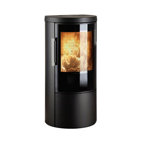
THE VIVALDI GAS STOVE
These instructions should be left with the customer for future reference
USER, INSTALLATIONAND SERVICING
INSTRUCTIONS
WARNING - THE COMBUSTION CHAMBER OF THIS STOVE SHOULD
ONLY BE OPENED AND SERVICED BY A QUALIFIED ENGINEER (i.e.
CORGI REGISTERED ENGINEER)
Hwam Heat Design
Nydamsvej 53
HØrning, DK-8362
Denmark
VIVMAN.PMD ISS 2

DearHwamCustomer
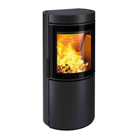
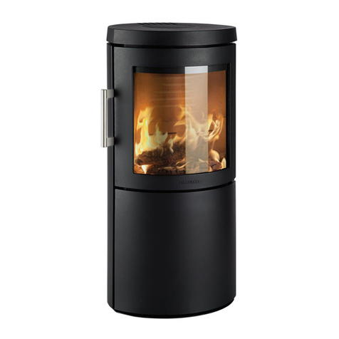
Vivaldi is a small, efficient stove that will spread a cheerful atmosphere and heat during all “four
seasons”.Thismakesit the idealchoiceforbothweekend cottages andsmallerlivingrooms.Behind
itscompact,well-proportionedexteriorliesathoroughlythought-outcombustiontechnology,which
ensuresapleasantindoor climateandextremelyefficient,environment-friendlycombustion.
Design:ArchitectAnders C. Fasterholdt.
CONTENTS
Important Safety Notice ..................................................................................................................... 3
General Fitting Information ...................................................................................................................................... 4
Battery type (Remote Versions only) ..................................................................................................................... 4
Using The Appliance............................................................................................................................. 5
Standard Manual Tap............................................................................................................................. 5
Advanced Manual Tap (Mertik Tap)............................................................................................... 6
Remote Control (Simple version) ................................................................................................... 7
Remote Control with climate control .......................................................................................... 8
Remote Control Electronic Ignition System ............................................................................ 9
Installation of the Stove................................................................................................................... 1 0
Flue Requirements .................................................................................................................................................... 10
Stove Location ............................................................................................................................................................ 10
Ventilation .................................................................................................................................................................... 11
Gas Connection .......................................................................................................................................................... 11
Pressure Testing .......................................................................................................................................................... 12
Connecting the Remote Control (where appropriate)................................................... 1 2
Simple Version Up and Lower control only ....................................................................................................... 12
Climate Control System ........................................................................................................................................... 12
Electronic Ignition System ...................................................................................................................................... 13
Arranging The Ceramic Fire-bed ................................................................................................ 1 4
Coal Pattern Arrangement...................................................................................................................................... 14
Log Pattern Arrangement ....................................................................................................................................... 15
COMMISSIONING THE STOVE ................................................................................................................................ 17
Servicing Instructions ....................................................................................................................... 1 7
Troubleshooting ........................................................................................................................................................ 17
Short Spares List ......................................................................................................................................................... 18
Technical Details .................................................................................................................................. 1 9
Dimension of Stove .................................................................................................................................................. 19

3
HWAM Vivaldi
IMPORTANT SAFETY NOTICE
This appliance has a ceramic Fire-bed arrangement;
this contains Refractory Ceramic Fibres, which are
man-made vitreous silicate fibres. Excessive expo-
sure to these materials can cause irritation to eyes,
skin and respiratory organs. Hence we recommend
that when handling these materials the release of
dust should be kept to a minimum. During installa-
tion and servicing we recommend that a HEPA fil-
tered vacuum be used to remove any dust and soot
in and around the fire. If any of the ceramic fire-bed
components need to be replaced we recommend
that the removed parts be sealed in a heavy-duty
polythene bag, and be labelled as RCF waste. RCF is
not“Hazardous waste”and can be disposed of at a
licensed tipping site for the disposal of industrial
waste.
The appliance incorporates an Oxygen Depletion
Sensor (ODS) Monitoring system.This is located on
the front of the burner, and must not be adjusted
by the installer. This ODS system must not be put
out of operation, and if any parts require changing,
only original manufacturer parts shall be used.
This appliance is designed to be used either Natu-
ral or LPG gas however, each individual appliance
is only capable of running off the type of gas speci-
fied at the time of purchase. It is important to note
that once a type of gas has been specified the stove
cannot run off any other type.The type of gas that
your stove is capable of burning is stated on the
data information panel.
This appliance has been designed, tested and ap-
proved to meet standards in place for product use,
performance and safety. Installation of your Stove
must comply with current building regulations. It is
therefore recommend that a CORGI engineer be
employed for this task. Taking particular notice of
“thermal inversion”The engineer will provide you
with information about the safety limits of the in-
stallation and should fix a notice plate in a place
where it can be readily seen.
This appliance is designed as an efficient heating
device and consequently all body parts become
very hot in use. Except for the control knob and con-
trol access door,which are designed to stay cool,all
other parts are working surfaces and should not be
touched.
The glass and frame on this appliance acts as a fire-
guard conforming to BS: 1945 – 1971 and satisfies
the Heating Appliance (Fireguards) regulations
1991. No part of the window or frame should be
permanently removed. It does not give full pro-
tection for young children or the infirm, extra pro-
tection should be considered for these conditions
conforming to BS 6539 or BS 6778.
Bearing in mind that the heat given off by this ap-
pliance may affect articles placed close to it, cur-
tains should not be placed within 30cm.
The appliance is not designed as a dryer. It is not
therefore recommended that the appliance be used
in such a manner. Do not place any articles within
30cm of this appliance as this may result in damage
to the articles.
The installation must be carried out in accordance
with the following regulations:
The Building Regulations issued by the Department
of the Environment, the Building Standards (Scot-
land) (Consolidation) Regulations issued by the
Scottish Development Department.
GENERALINFORMATION

4HWAM Vivaldi
BS 1251, BS 5440 part 1, BS 5871 part 2, BS 6461 part
1, BS 6891 and BS 8303
In the Republic of Ireland the installation must also
conform to the relevant standards, particularly in
regard to flue sizing and ventilation. Refer to docu-
ments IS813, ICP3, IS327 and any other rules in force.
This appliance must be installed in accordance with
the rules in force and used only in a sufficiently ven-
tilated space, and is intended for use on a gas in-
stallation with a governed meter.
Before installation, check that this appliance is com-
patible with local distribution conditions, nature of
gas and pressure.The technical specification of this
appliance is given on the rear page of this manual.
This appliance should not be used if the
Glass is broken, and should never be
used with the Door open.
Inlet pipe connection 8mm compression
Chimney requirements Class I or Class II
Flue monitor Oxygen Depletion Sensor
NOxlevel Class 1 (Nat. Gas), Class 5 (LPG)
User control:Variable rotary control inc.integrated
Piezo ignition, Permanent pilot facility, Flame fail-
ure device and Oxygen Depletion Cut-out.
Battery type (Remote Versions only)
Receiver: 4x AA, R6 size (mounted at back of stove)
Transmitter: PP3 (Alkaline only).
General Fitting Information
GENERALINFORMATION

5
HWAM Vivaldi
USERINFORMATION
IT IS VERY IMPORTANT TO READ THESE
INSTRUCTIONS THOROUGHLY BEFORE
LIGHTING.
This appliance will produce an odour and/or smoke
for the first few hours of use when new.Please ven-
tilate the room when first lighting from new.
There is a flue spillage monitoring system fitted to
this appliance, which cuts off the gas supply upon
the detection of spilled flue gasses. If this system
activates and the appliance cuts out, allow 3 min-
utes before retrying the ignition, noting that the
control tap must first be returned to the off posi-
tion. If the pilot will not light, allow a further 3 min-
utes or sufficient time for switch to reset. If cutting
off persists, then a professionally qualified (i.e.
CORGI registered) engineer should be informed.
The controls are located behind the access panel,
which is the swing out panel underneath the main
door. The standard control is a basic rotary tap,
which has a single control knob. As an optional ex-
tra a remote control version is available which has
two rotary control knobs. The remote control ver-
sion must be specified at time of ordering
All versions of this appliance operate with a tradi-
tional pilot light.The pilot light is located in the cen-
tre of the burner, and is visible through the front
window. If the Flame Supervision Device Actuat-
ing Flame (the Pilot Light) is extinguished either by
intention or not, no attempt should be made to re-
light until 3 minutes have elapsed.
IMPORTANT: Immediately after lighting,the ap-
pliance must be left on HIGH for ten minutes in
order to warm up the chimney.
USING THE APPLIANCE STANDARD MANUAL TAP
Igniting the pilot light.
Depress control knob fully.
Whilst depressed, turn knob 90° anticlockwise to
“PILOT” setting. Re-
peat until pilot light
is visibly lit.This may
take a few attempts.
KEEP KNOB DE-
PRESSED AT THIS
POINT FOR 15 – 20
SECONDS.
Upon releasing the knob, the permanent pilot will
remain lit, if not repeat process.
Running the appliance at high
output.
Ignite permanent
pilot as shown
above.
With the control
knob at“PILOT”set-
ting, turn in an anti
clockwise direction
to“HIGH”setting.
The appliance is now burning at its highest operat-
ing output.
Running the appliance at low
setting.
Ignite permanent
pilot as shown in
“Igniniting the pilot
light” and run ap-
pliance at “HIGH”
setting for a mini-
mum of 10 min-
HIGH
LOW
PILOT
PIEZO
IGN OFF
HIGH
LOW
PILOT PIEZO
IGN
OFF
HIGH
LOW
PILOT
PIEZO
IGN OFF

6HWAM Vivaldi
utes.
With control knob at“HIGH”setting,turn in a clock-
wise direction to“LOW”setting,a slight click can be
felt when low is engaged
The appliance is now burning at its lowest operat-
ing output.
Output can be set at a variable rate between“LOW”
and “HIGH”; this can be increased by turning the
control knob progressively in an anti-clockwise di-
rection (from“LOW”or clockwise from“HIGH”), un-
til the desired level is achieved.
Extinguishing the appliance back to
permanent
pilot setting
From any heat set-
ting, turn the knob
in a clockwise direc-
tion through the
“LOW” setting (a
click will be felt as
the knob passes through“LOW”) to the“PILOT”po-
sition
Extinguishing
the appliance
fully
From any heat set-
ting,turn to“PILOT”.
Depress knob fully
andturnclockwiseto
“OFF”position.
HIGH
LOW
PILOT
PIEZO
IGN OFF
HIGH
LOW
PILOT
PIEZO
IGN OFF
ADVANCED MANUAL TAP (MERTIK
TAP)
Igniting the Pilot Light
Turn the Right-hand knob slightly anti-clockwise
towards the ignition position until reaching stop,
depress and hold for five seconds (only pilot gas
flows).
Whilst still depressed, turn further in an anti-clock-
wise direction to activate the piezo. If the pilot does
not light, re-
peated immedi-
ately.
Continue to
keep the knob
depressed for a
further 10 sec-
onds, after the pilot has been lit.
Upon releasing the knob, the permanent pilot will
remain lit, if not return to off position and repeat.
Running the appliance at high
output
Ignite permanent pilot as shown in “Igniting the
pilot light”.
Turn the Right-
hand control
knob anti-
clockwise to
the setting,
which shows
the larger flame.
Turn the Left-hand control knob anti-clockwise to
the highest setting (large flame).
The appliance is now burning at its highest operat-
ing output.
Running the appliance at low
USERINFORMATION

7
HWAM Vivaldi
setting
Ignite perma-
nent pilot and
run appliance
at“High”setting
for a minimum
of 10 minutes as shown above.
With the Left-hand control knob at the highest set-
ting, rotate in a clock-wise direction to the lowest
setting (filled circle).
The appliance is now operating at its lowest oper-
ating output.
Extinguishing
the
appliance
back to
permanent
pilot
setting
From any heat setting, turn the Right-hand knob in
a clockwise direction to the “Pilot” position (the
smaller flame).
Extinguishing
the
appliance
fully
From any heat
setting,turn to“Pilot”as in“Extinguishing the appli-
ance back to permanent pilot setting”.
Depress the same knob slightly and turn clockwise
to “Off” position (filled circle).
USERINFORMATION
REMOTE CONTROL (SIMPLE
VERSION)
Ignite the pilot as described for the “Advanced
Manual Tap” above. Turn Right-hand control anti-
clockwise until
it is on the large
flame setting.
You are now
able to use the
remote control.
To increase the
flame, the top button should be depressed. Press-
ing the lower button on
the handset will reduce
the flame. It is also pos-
sible to turn the main
burner all the way
down so that it is effec-
tively off, leaving only
the pilot ignited.
When using the remote
control system, the appliance also maintains full
manual control. Hence the stove can be operated
using either the Manual Controls of the Remote
Handset.

8HWAM Vivaldi
REMOTE CONTROL WITH CLIMATE
CONTROL
Setting the Display
After connecting the battery or by si-
multaneously pressing AUTO and
TIMER, the display flashes.You are in
set mode.
From set mode,press AUTO to switch
from °F (and 12 hour clock) to °C (and
24 hour clock) or vice versa.
The display will automatically return
to manual mode after some time, but
you may immediately return to
manual by depressing the TIMER but-
ton.
Setting the current Time
After connecting the battery or by simultaneously
pressing AUTO and TIMER, the display flashes.You
are in set mode.
From set mode, press (K) to set the hour and (M) to
set the minute.
Wait or press TIMER to return to“manual“ mode.
Programming the Desired Set
Temperature
Press AUTO until the display flashes.
Press (K) or (M) to set the desired temperature.
Wait or press AUTO to switch to automatic mode.
A sensor in the transmitter measures the room tem-
perature. The controller compares the room tem-
perature with the set temperature and sends a sig-
nal to the receiver to turn the gas valve motor,which
adjusts the flame height accordingly.
Programming the Timer
Press TIMER until P1 flashes (period 1, heating
cycle on).
Set the time for the beginning of the
first heating period by pressing (K)
for hour and (M) for minute.
Press TIMER again, P1%%
%%
%
appears.
Set the time for the end of the first
heating period.
Press TIMER again to set the second
heating period P2(heat on) and
P2%%
%%
%
(heat off).
Store both heating periods by press-
ing TIMER again.
If only one heating period is desired,
program the same time for P2and
P2%%
%%
%
.
Manual Mode for Manual Flame
Height Adjustment
(MAN in display)
Press (K) to turn on the fire (main burner) or to in-
crease flame height
Press (Kto decrease flame or to turn down to pilot.
To incrementally increase or decrease the flame
height lightly tap either the (K) or (M) button.
The“send“ symbol appears in the upper left corner
of the display when either button is depressed.
The LED of the receiver flashes when knob B of the
valve reaches its end stops.
Automatic Mode for Temperature
Control
(AUTO in display)
Briefly press AUTO.The set temperature will appear
briefly before the display reverts to the room tem-
perature.
USERINFORMATION

9
HWAM Vivaldi
Timer Mode (TIMER in display)
During heating periods P1and P2, the tempera-
ture is controlled in the same manner as in auto-
matic mode.
When the timer program turns to%%
%%
%
(heating cycle
off),the motor will turn the valve to pilot and there
is no temperature control. This minimizes battery
consumption.
You may press AUTO to verify the set-temperature
and then press TIMER to return to timer mode.
You may press either the (K) or (K) button from any
mode for manual override.
To prolong battery life, we recommend switching
the transmitter to manual mode and turning the
fire to pilot with the (K) button before turning the
appliance off. If the transmitter is left in automatic
or timer mode, the batteries will continue to be used
when the appliance is off.
USERINFORMATION
REMOTE CONTROL ELECTRONIC
IGNITION SYSTEM
Igniting the Appliance.
Simultaneously press
the“ OFF”and“K”but-
tons of the receiver for
ignition.
An acoustic signal indi-
cates that the start se-
quence has begun.
The electronic system
then checks that the
main gas is flowing and
ignites the main burner; this may take up to 20 sec-
onds.
(NOTE: During start-up, override knob cannot be
in Manual position.)
Adjusting the Heat Setting
You are now able to use the remote control.To in-
crease the flame, the top button (K) should be de-
pressed. Pressing the lower button (M) on the hand-
set will reduce the flame.
It is also possible to turn the main burner all the
way down so that it is effectively off, leaving only
the pilot ignited.
Extinguishing the Appliance Fully
From any heat setting,press the“ OFF”button for
a few seconds. This will cause the burner to fully
extinguish.
The system has a safety interlock which will not al-
low the Ignition until the Interlock rests (this may
take a few minutes).

10 HWAM Vivaldi
INSTALLER INFORMATION
INSTALLATION OF THE STOVE
This appliance must be installed by a qualified
CORGI gas engineer, and must be installed in ac-
cordance with the Regulations and Standards listed
in the front of this Manual.
Failure to comply with the instructions in this
manual, or the regulations and standards will re-
sult in the Guarantee being void and could have
hazardous consequences.
Flue Requirements
The flue, which the appliance is to be attached, must
conform to BS 5440 pt.1, and may be either a class 1
or class 2 chimney.Before the appliance is installed,
the flue system or chimney must be inspected and
passed as suitable.
This stove is suitable for installation onto either flex-
ible or fabricated steel flue system and is also suit-
able for pre-cast flues, pre-cast chimney block, pre-
cast flue block and ridge tile vent.
The minimum effective height of the flue must be
three metres measured from the hearth to the ter-
mination of the flue. If the flue has any non-vertical
sections, the height should be increased in line with
BS 5440 pt.1. Prior to installation, the installer should
ensure that the flue is free from obstruction, ideally
should be swept and subsequently smoke tested.
Ensure that any dampers are fixed in a permanently
open position.
The appliance has been designed with a built in
draught diverter, and as such no further draught
diverter need be fitted to the flue system.
Flue Options
This stove is equipped with an interchangeable flue
system,so that it can be fitted either as Rear or Top
Flue,however,the stove is delivered ready to use as
a Top Flue appliance.
If the stove is to be fitted and used as a rear flue
appliance, then the following procedure must be
followed.
1. Break out and remove the curved external cover
plate in the rear of the appliance.
2. Remove the blanking plate from the rear of the
stove and the flue connector from the top of the
stove.
3. Reinstall the flue connector in the rear of the stove
and the blanking plate in the top of the stove.
Stove Location
The stove must stand on a fireproof hearth, which
must be of a non-combustible material which must
extend 50mm in front of the stove.
The hearth must not be capable of inadvertent cov-
ering by a rug or carpet. This may be achieved by
either the hearth being 50mm above the level of
the floor, or a fender or kerb around the hearth to a
height of 50mm.
The appliance must not be fitted against a rear wall
constructed from a combustible material; a gap of
300mm should be given all round the stove before
combustible materials may be used in the wall con-
struction.
If the appliance has to be located in an opening,
the minimum clearance from non-combustible
materials is shown in the figure below.

11
HWAM Vivaldi
The stove must be located at least 280mm from any
combustible materials.
A combustible shelf may be fitted over the appli-
ance, if in the case of a 150mm or less deep shelf;
there is at least 280mm clearance above the top of
the stove.The shelf depth may increase at the same
rate as the increase in clearance; i.e. a shelf depth of
200mm would require a clearance of 330mm.
Ventilation
This gas stove is rated at less than 7kW; it therefore
does not normally require additional ventilation in
the room to conform to BS 5871 pt.2. However it is
important that adequate air for complete combus-
tion is available, and also if other gas appliances or
extractor fans are fitted in the same room or adja-
cent area, then it will be necessary to refer to BS
6714 and BS 5440 :pt.2. to ascertain the additional
ventilation requirements.
Gas Connection
It is important to ensure that all pipe work installed
is fitted in accordance with BS6891 and is capable
of supplying sufficient gas flow and pressure to
meet the minimum pressures Technical section of
this manual. A minimum pipe size of 15mm should
be used for the gas supply to within 1 metre of the
appliance. 8mm pipe may only be used for the final
connection to the stove, or within 1 meter of the
appliance. An 8mm nut and olive is supplied with
the stove for the final pipe joint.
A gas supply tap must be installed in the supply
pipe work in a location that is easily accessible, such
that the appliance may be isolated if necessary.
Do not make any connections to the appliance until
all supply pipes have been purged to expel any dust
or debris. Failure to do this may result in a blocked
injector or tap and will invalidate the guarantee
Although a gas soundness test is made on all appli-
ances before they leave the factory, the appliance
INSTALLER INFORMATION

12 HWAM Vivaldi
should be tested for soundness before operating
the stove. This is to ensure that the burner has not
been damaged in transit.
Pressure Testing
The gas pressure to the burner must be measured;
this should be measured with all gas appliances
after the gas meter operating on full, including this
stove.
CONNECTING THE REMOTE
CONTROL (WHERE APPROPRIATE)
Simple Version Up and Lower con-
trol only
This requires no external electrical power to oper-
ate. The receiver unit has a unit that has only one
lead. This lead has two plugs (of different sizes),
these will plug into the two spade plugs on the front
of the Gas Control unit.
Install the batteries into the receiver and the hand-
set, these will be 4 x 1,5V AA alkaline and 9V PP3
alkaline respectively.
This Receiver/Handset works using sound waves,
and as such no direct line of sight is required be-
tween the two items. Provided that the distance
between the receiver and handset is less than 10m,
the system will work.
The receiver unit can be hidden away under or be-
hind the stove, ensure that the receiver is located in
an area that has a temperature below 60ºC, and that
the customer knows where the receiver is for fu-
ture battery replacement.
Check the system.
Climate Control System
This requires no external electrical power to oper-
ate. The receiver unit has a unit that has only one
lead. This lead has four plugs (two larger plugs of
INSTALLER INFORMATION
Plugs
Battery Cover
Lead
Receiver
Spade Connections Motor Spade Connections
Micro Switch
Spade Connections
Motor Plugs
Micro Switch Plugs
Receiver Lead

13
HWAM Vivaldi
different sizes and two plugs the same size). The
two larger plugs fit onto the two spade plugs on
the top of the Gas Control unit, the orientation of
these plugs is important.The two smaller plugs fit
on to the small spade connectors on the side of the
control unit.
Install the batteries into the receiver and the hand-
set; these will be 4 x 1,5V AA alkaline and 9V PP3
alkaline respectively.
This Receiver/Handset works using sound waves,
and as such no direct line of sight is required be-
tween the two items. Provided that the distance
between the receiver and handset is less than 10m,
the system will work.
The receiver unit should be mounted at the back of
the stove, ensure that the receiver is located in an
area that has a temperature below 60ºC, and that
the customer knows where the receiver is for fu-
ture battery replacement.
Check the system.
Electronic Ignition System
This requires no external electrical power to oper-
ate. The receiver unit has a unit that has only one
lead.This lead has one single plug.This plug fits into
the connector block on the front of the Gas Control
unit, the orientation of this plug is important. Install
the batteries into the receiver and the handset;
these will be 4 x 1,5V AA alkaline and 9V PP3 alka-
line respectively.
This Receiver/Handset works radio frequency, and
as such no direct line of sight is required between
the two items. Provided that the distance between
the receiver and handset is less than 10m, the sys-
tem will work.
The RF remote is preset to a unique code that, if
necessary, can be easily changed in the remote
handset. A four-position DIP switch enables any of
16 pre-selected codes. Pressing the switch on the
receiver activates the new code.
The receiver unit can be hidden away under or be-
hind the stove, ensure that the receiver is located in
an area that has a temperature below 60ºC, and that
the customer knows where the receiver is for fu-
ture battery replacement.
Check the system.
INSTALLER INFORMATION
Handset
Lead
Connection
Receiver
Control Unit Lead
Connection

14 HWAM Vivaldi
INSTALLER INFORMATION
ARRANGING THE CERAMIC FIRE-BED
Coal Pattern Arrangement
Only the ceramics supplied with this appliance are
to be used.The coals must be laid only as shown on
the following pages. Replacement coals, ceramic
and mat are available from your dealer, but should
only be installed by a qualified installation engi-
neer.
The stove should arrive with the following parts as
required for the coal layout:
1 No. Ceramic Mat
1 No. Matrix
6 No. Large Coals
5 No. Small Coals
Please note that the Matrix changes dependant on
Gas type.
Natural Matrix - 95mm deep
LPG Matrix - 65mm deep
Please check that the correct parts and quantities
have been delivered before commencing installa-
tion.
PROCEEDURE FOR ARRANGEMENT
Ensure that the Pilot Assembly remains unob-
structed when arranging the coals. Note that there
is a viewing slot in the matrix such that the Pilot
Flame will be visible when lit, this must also be kept
clear.
Please note that once the stove is lit, the coals be-
come very hot, care must be taken when adjusting
coals after the appliance has been lit and Hwam
Heat and Design accept no responsibility for any
injury sustained whilst handling hot ceramics.
Stage 1
Lay the Ceramic Mat on top of the Burner as shown,
making sure that all holes including the 12 small
cross lighting holes are not blocked, and that the
pilot assembly is not obstructed.
Stage 2
Place the Ceramic Matrix on top of the mat and
burner.

15
HWAM Vivaldi
INSTALLER INFORMATION
Log Pattern Arrangement
Only the ceramics supplied with this appliance are
to be used.The logs must be laid only as shown on
the following pages. Replacement logs, embers and
mat are available from your dealer,but should only
be installed by a qualified installation engineer.
The stove should arrive with the following parts as
required for the coal layout:
1 No. Ceramic Mat
1 No. Bag of Embers
4 No. Ceramic Logs
Please check that the correct parts and quantities
have been delivered before commencing installa-
tion.
PROCEEDURE FOR ARRANGEMENT
Ensure that the Pilot Assembly remains unob-
structed when arranging the coals. Note that there
is a viewing slot in the matrix such that the Pilot
Flame will be visible when lit, this must also be kept
clear.
Please note that once the stove is lit, the coals be-
come very hot, care must be taken when adjusting
coals after the appliance has been lit and Hwam
Heat and Design accept no responsibility for any
injury sustained whilst handling hot ceramics.
Stage 1
Lay the Ceramic
Mat on top of
the Burner as
shown, making sure that all holes including the 12
small cross lighting holes are not blocked, and that
Stage 3
Place the 6 Large Ceramic Coals on the back of the
Matrix.
Stage 4
Place the 5 Small Ceramic Coals around the front of
the matrix.

16 HWAM Vivaldi
INSTALLER INFORMATION
the pilot assembly is not obstructed.
Stage 2
Scatter the contents on the bag of Embers evenly
over the top of the Burner Mat, paying careful at-
tention not to block the Pilot light.
Stage 3
Place the Large “Charred” Log across the back of
the burner.The“Charred”face should be facing for-
ward, with the“Knot”to the top and the rear of the
log against the rear of the stove.
The remainder of the Log arrangement is different
for Natural or LPG gas.The logs must be set out in
accordance with the directions for the appropriate
gas type.
LPG
The Medium sized“Y”shape log will be placed first;
this will be located to the Left of the Burner, with
fork of the “Y” pointing upwards. The base of the
log should rest against the Log Bar at the front of
the stove. Make sure that the Log does not obstruct
the pilot.
Next the Larger of the two remaining logs will be
placed around the remainder of the front of the Fire-
box, following the Log Bar. This will be orientated
such that the Base of the log is against the base of
the first log and the pilot light.
The final log will be placed lying across the front
log leading to the inside of the rear log.The log will
be placed such that the“Charred”end is inside the
fire, with the fatter end on the front log.
The picture above shows the arrangement, as it
should look for the LPG.
Natural Gas
The Medium sized“Y”shape log will be placed first;
this will be located to the Left of the Burner, with
fork of the “Y” pointing downwards. The extent of
the log should be in the corner of the stove touch-
ing the log bar and the side of the stove. The log
should then be laid such that its base is in the cor-
ner of the side and rear of the stove.
The smallest log should be placed next.This will be
placed at the very right hand side and orientated
such the“Charred”end of the log is to the front,with
the fatter end sitting on top of the rear log.

17
HWAM Vivaldi
The final log should be placed in the main part of
the Firebox. The log will be placed such that the
base of the log is at the top and at the rear of the
stove.The picture demonstrates how the arrange-
ment should look for Natural gas.
INSTALLER INFORMATION
COMMISSIONING THE STOVE
A spillage test MUST be made before the installed
stove is left with the customer.
Carry out the test by first closing all doors and win-
dows in the room containing the stove.
Ensure that the fire is burning at full rate for a mini-
mum of 5 minutes to warm the flue.
Using a smoke match, run along the edge of the
draught diverter.The smoke should be drawn into
the draught diverter.The test should be made over
the full width of the draught diverter, and the test
may be done from either left or right.
If most of the smoke is not drawn into the draught
diverter leave for a further 10 minutes and repeat.
If there is a fan in the room (or adjacent rooms) the
spillage test be repeated with the fan running on
full power and all connecting doors between the
fire and fan left open.
If there are problems, the chimney/flue may require
attention. Isolate the stove and seek expert advice.
The stove will produce an odour and/or smoke for
the first few hours of use. Please ventilate the room.
SERVICING INSTRUCTIONS
The following outlines only the minimum work that
should be performed on an annual basis.This serv-
ice work, like any other work on the appliance, must
only be done by a qualified and competent engi-
neer who is CORGI registered.
Open the door and remove all ceramics.
Remove mat from top of burner.
Remove any debris from the top of the burner us-
ing a vacuum cleaner and brush.
Inspect the burner unit.
Perform an ignition check.
Perform a flame failure check
There should be no need to service the burner. If
however this is required, then the engineer should
check the setting pressure at inlet to burner; the
correct pressure is shown at the rear of the manual.
Brush off and replace ceramic arrangement as ear-
lier in this manual, replacing any broken or dam-
aged pieces.
Check all seal on door (including glass) and replace
the Door.
Check the installation for gas leaks.
Check flue for clearance of products of combustion.
If any parts need to be replaced use only genuine
Hwam parts, non-standard parts will invalidate the
guarantee and may be dangerous.
Troubleshooting
The gas pilot will not ignite or stay lit?
Ensure the gas is turned on at the appliance and
the meter/cylinder.
Depress the control knob for at least twenty sec-
onds once the pilot is alight to ensure the opera-
tion of the safety thermocouple valve.
Ensure that the pilot injector is not obstructed or

18 HWAM Vivaldi
blocked and it is free from any dust or dirt.
Ensure that the thermocouple has not been dam-
aged in transit.This is a very delicate Electro-mag-
netic device.
On propane,the cylinder could be empty.
The pilot is not burning or performing correctly?
Ensure the pilot flame is the correct size for the type
of gas. The flame should be focused on the ther-
mocouple probe.
The pilot flame will have been set correctly in the
factory.
The Main Burner does not seem to be burning cor-
rectly?
Ensure adequate gas pressure to the appliance.Test
pressure by releasing the pressure test screw and
applying a manometer. Ensure adequate volume
of gas is being used. Once the fire is burning on
maximum, turn off all other gas appliances in the
house and calculate the fuel being burned from the
gas meter.
Make sure that the burner is burning correctly. The
flame should be even across the top of the burner
before any coals are placed on top.
SERVICING INFORMATION
Short Spares List
Only original Hwam parts may be used when re-
placing parts on this appliance.
Matrix inc. coals (Natural) YG76142
Matrix inc. coals (LPG) YG76342
Ceramic Log set CG48142
Burner ceramic Mat YG76131
Glass window 22-0741
Rope Kit 22-0744
Pilot Assembly (Natural) CG06178
Pilot Assembly (LPG) CG20078
Injector (Natural) YG75077
Injector (LPG) YG56177
Seagas Control Tap YG56379
Mertik Control Tap CG20179

19
HWAM Vivaldi
TECHNICALINFORMATION
Propane
Gas Category I2H I2E I2E+ I2L I3P
Gas G20 G20 G20/G25 G25 G31
Supply Pressure (mbar) 20 20 20/25 25 37
Countries AT,DK,ES, DE,LU BE,FR NL ES,FR,GB,
of FI,GB,GR,IE, GR,IE,IT,
Destination IT,PT,SE PT
Product Identification No. 0063BP5334 0063BP5334 0063BP5334 0063BP5334 0063BP5334
Nominal Input (Gross kW) 6.7 6.7 6.7/6.2 6.2 6.6
EfficiencyClass 22222
NoxClass 11115
Gas Rate (max. m³/hr) 0.638 0.638 0.638/0.682 0.682 0.242
Burner Pressure (Hot mbar) 17.2 17.2 17.2/21.7 21.7 35.4
Gas Rate (min. m³/hr) 0.25 0.25 0.250/0.268 0.268 0.11
Burner Pressure (Hot mbar) 3 3 3.0/3.7 3.7 8.8
Burner Injector (Bray) 400 400 400 400 180
Pilot Burner (SIT OP) 9043 9043 9043 9043 9228
Natural
TECHNICAL DETAILS
Dimension of Stove
Table of contents
Other HWAM Stove manuals
Popular Stove manuals by other brands

Diamond
Diamond E9/6PQFA12 operating instructions

F2 Fires
F2 Fires Vue Landscape Installation and operating manual

Plow & Hearth
Plow & Hearth 12435 user manual

Whitfield
Whitfield Profile 20 FS-2 Installation and operation manual

Duluth Forge
Duluth Forge FDSR25 Operation and installation manual

CPL
CPL PORTA OVEN PRO 40 user manual