Hytera TC-780 VHF User manual

PREFACE
Thank you for purchasing Hytera TC-780 Professional Portable Radio.
This easy-to-use radio will deliver you secure, instant and reliable com-
munications at peak efciency. Please read this manual carefully before
use. The information presented herein will help you to derive maximum
performance from your radio.
MODELS COVERED IN THIS MANUAL
TC-780 VHF Two-way Radio
TC-780 UHF Two-way Radio
Note: This manual is intended for 5-Tone models only.

1
Safety Information ---------------------------------------------- 3
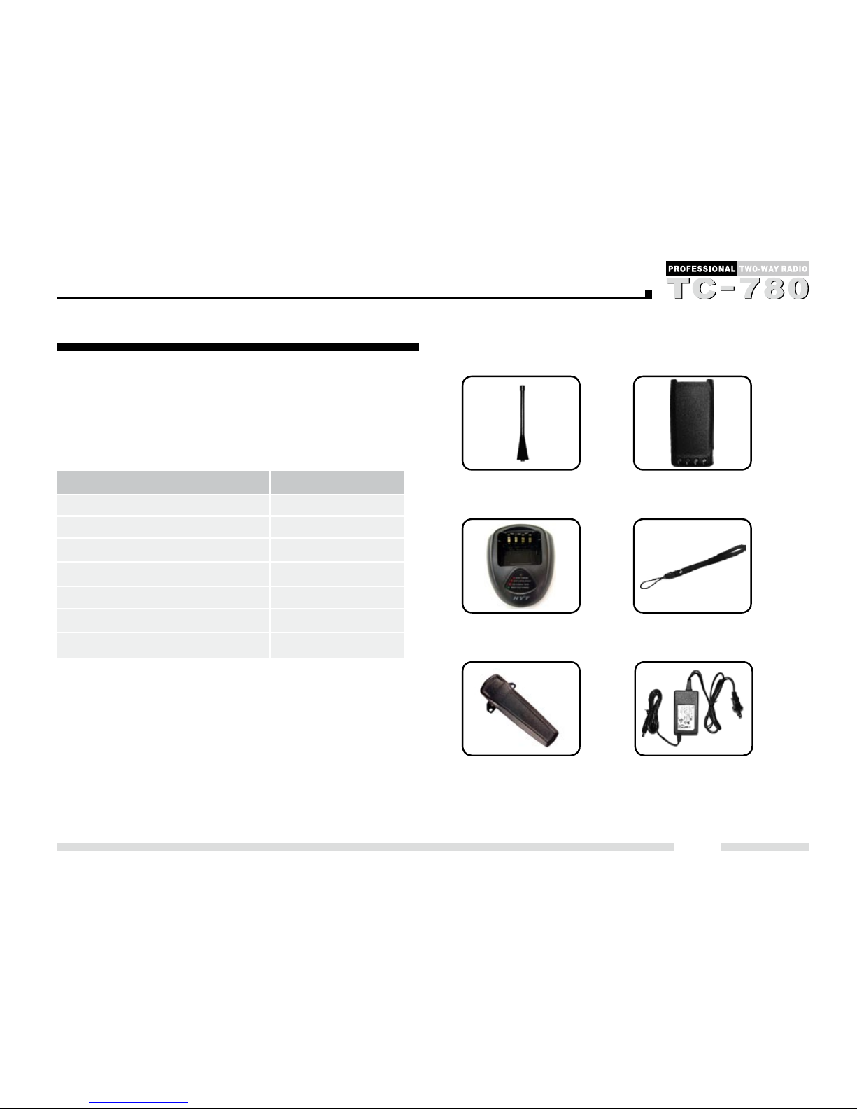
Product Inspection --------------------------------------------- 4
Radio Overview -------------------------------------------------- 5
Battery Information --------------------------------------------- 8
Antenna Information ------------------------------------------- 11
Assembly and Disassembly --------------------------------- 12
Attaching/Removing the Battery------------------------ 12
Attaching/Removing the Antenna ---------------------- 13
Attaching/Removing the Belt Clip---------------------- 13
Removing the Accessory Cover------------------------ 14
Attaching the Earpiece/Microphone ------------------- 14
LCD Icons---------------------------------------------------------- 15
Menu----------------------------------------------------------------- 17
Basic Operations ------------------------------------------------ 20
Adjusting the Volume-------------------------------------- 20
Selecting a Zone ------------------------------------------- 20
Selecting a Channel --------------------------------------- 20
Transmitting a Voice Call--------------------------------- 20
Receiving a Voice Call ------------------------------------ 20
5-Tone Call--------------------------------------------------- 20
5-Tone Function -------------------------------------------- 24
HDC2400™-------------------------------------------------- 25
Auto Contact ------------------------------------------------ 26
Scan ----------------------------------------------------------- 27
Phone --------------------------------------------------------- 28
Emergency--------------------------------------------------- 29
Lone Worker------------------------------------------------- 30
Man Down --------------------------------------------------- 31
Time-Out-Timer--------------------------------------------- 31
Optional Functions----------------------------------------- 32
Programmable Auxiliary Functions ----------------------- 36
Advanced Operations ----------------------------------------- 37
Off-------------------------------------------------------------- 37
Channel Down ---------------------------------------------- 37
Channel Up -------------------------------------------------- 37
Zone Down -------------------------------------------------- 37
Zone Up ------------------------------------------------------ 37
Monitor-------------------------------------------------------- 37
Monitor Momentary ---------------------------------------- 37
Squelch Off -------------------------------------------------- 37
Squelch Off Momentary ---------------------------------- 37
Cancel Call -------------------------------------------------- 38
Display Channel Alias------------------------------------- 38
Display Channel Frequency ----------------------------- 38
Switch Display ---------------------------------------------- 38
UST------------------------------------------------------------ 38
Power Adjust ------------------------------------------------ 38
Scan ----------------------------------------------------------- 38
Nuisance Channel Temporary Delete----------------- 38
Exit Emergency--------------------------------------------- 38
Enable Emergency ---------------------------------------- 38
VOX (Voice-Operated Transmit) ----------------------- 39
Keypad Lock ------------------------------------------------ 39
Talk Around -------------------------------------------------- 39
Contents

2
Select Squelch Level-------------------------------------- 39
Home Channel---------------------------------------------- 39
Backlight------------------------------------------------------ 39
Scrambler ---------------------------------------------------- 39
Voice Compandor ------------------------------------------ 39
Call Forward------------------------------------------------- 39
Whisper------------------------------------------------------- 40
Lone Worker------------------------------------------------- 40
Man Down --------------------------------------------------- 40
Auto Contact ------------------------------------------------ 40
Radio Call ---------------------------------------------------- 40
Contact List -------------------------------------------------- 40
Status List---------------------------------------------------- 40
Channel Menu Shortcut ---------------------------------- 40
Missed Call -------------------------------------------------- 40
Received Call ----------------------------------------------- 40
Keypad Mode ----------------------------------------------- 40
Call 1- Call 5------------------------------------------------- 41
Patrol Receive ---------------------------------------------- 41
Encrypt-------------------------------------------------------- 41
Secret Key Switch ----------------------------------------- 41
Troubleshooting ------------------------------------------------- 42
Care and Cleaning ---------------------------------------------- 43
Optional Accessories ------------------------------------------ 44
Contents

3
The following safety precautions shall always be observed
during operation, service and repair of this equipment.
◇ This equipment shall be serviced by qualied technicians
only.
◇Do not modify the radio for any reason.
◇Use only Hytera supplied or approved batteries and
chargers.
◇Do not use any portable radio that has a damaged
antenna. If a damaged antenna comes into contact with
your skin, a minor burn can result.
◇Turn off your radio prior to entering any area with explosive
and ammable materials.
◇Do not charge your battery in a location with explosive
and ammable materials.
◇To avoid electromagnetic interference and/or compatibility
conicts, turn off your radio in any area where posted
notices instruct you to do so.
◇Turn off your radio before boarding an aircraft. Any use
of a radio must be in accordance with airline regulations
or crew instructions.
◇Turn off your radio before entering a blasting area.
◇For vehicles with an air bag, do not place a radio in the
area over an air bag or in the air bag deployment area.
◇Do not expose the radio to direct sunlight over a long
time, nor place it close to heating source.
◇When transmitting with a portable radio, hold the
radio in a vertical position with the microphone 3 to 4
centimeters away from your lips. Keep antenna at least
2.5 centimeters away from your body when transmitting.
Safety Information

4
Product Inspection
Please unpack the package box carefully and check that
all items shipped were received; report any missing or
damaged items to your dealer.
Accessories
Antenna Li-Ion Battery
MCU Rapid-rate
Charger
Leather Strap
Belt Clip Switching Power (for use with
different power cords in different
countries and areas)
Note: Frequency band is marked on the label of antenna,
if not, please refer to the label on the radio unit for detailed
frequency band information.
Item Qty. (PCS)
Antenna 1
Belt Clip 1
Leather Strap 1
Li-Ion Battery 1
MCU Rapid-rate Charger 1
Switching Power 1
Owner’s Manual 1

5
Radio Overview
1. PTT (Push-to-Talk) Key
2. SK1 (Side Key 1)
3. SK2 (Side Key 2)
4. Antenna
5. Microphone
6. Speaker
7. LCD Display
8. Function Keypad
9. Numeric Keypad
10. TK (Top Key)
11. Channel Selector Knob
12. Radio On-Off /Volume Control
Knob
13. LED Indicator
14. Accessory Jack
15. Battery Latch
16. Belt Clip
17. Battery
18. Screw, Belt Clip
19. Charging Piece

6
PTT (Push-to-Talk) Key
Press and hold down the PTT key to transmit; and release
it to receive.
SK1 (Side Key 1)
Programmable function key.
SK2 (Side Key 2)
Programmable function key.
Radio On-Off/Volume Control Knob
Rotate the knob clockwise to turn the radio on, and rotate
the knob fully counter-clockwise until a click is heard to
turn the radio off.
Turn the knob clockwise to increase the volume, or count-
er-clockwise to decrease the volume.
Function Keypad
●Exit key
Use the Exit key to return to the previous menu.
●Up key
●Down key
●Menu/Select key
Used to enter the Menu mode. When you are in the Menu
mode, this key is also used to make menu selections.
Exit Up Menu / Select
Call Back Down Redial
Numeric Keypad
Used to enter information for programming the radio's
lists.
Radio Overview

7
Radio Overview
TK (Top Key)
Programmable function key.
Channel Selector Knob
Rotate the knob to select a desired channel.
Accessory Jack
The jack is used to connect audio accessories, or other
accessories such as programming cable.
LED Indicator
Status LED
Transmitting Glow red.
Receiving Glow green.
Transmitting Call Alert Glow orange.
Call Alert (5-Tone) Flash orange (less frequently)
Missed Call Alert
(5-Tone)
Flash orange (more frequently)
Call Alert
(HDC2400™)
Flash orange (more frequently)
Selective Call Alert
(HDC2400™)
Group call, zone call, broadcast: flash
orange once; Individual call: ash orange
twice
Scanning Flash green
Low battery alert Flash red

8
Initial Use
New batteries are shipped uncharged from the factory.
Charge a new battery for 5 hours before initial use. The
maximum battery capacity and performance is achieved
after three full charge/discharge cycles. If you notice the
battery power runs low, please recharge the battery.
Applicable Battery Packs
To reduce the risk of injury, charge only the battery speci-
fied by the manufacturer. Other batteries may burst,
causing bodily injury and damage.
Caution:
1. To avoid risk of personal injury, do not dispose of bat-
teries in re!
2. Dispose of batteries according to local regulations (e.g.
recycling). Do not dispose as household waste.
3. Never attempt to disassemble the battery.
Battery Tips
1. When charging your battery, keep it at a temperature
among 5℃~ 40℃. Temperature out of the limit may
cause battery leakage or damage.
2. When charging a battery attached to a radio, turn the
radio off to ensure a full charge.
3. Do not cut off the power supply or remove the battery
when charging a battery.
4. Never charge a battery that is wet. Please dry it with a
soft cloth prior to charge.
5. The battery will eventually wear out. When the operat-
ing time (talk-time and standby time) is noticeably
shorter than normal, it is time to buy a new battery.
To Prolong Battery Life
1. Battery performance will be greatly decreased at a
temperature below 0℃. A spare battery is necessary
in cold weather. The cold battery unable to work in this
situation may work under room temperature, so keep it
for later use.
2. The dust on the battery contact may cause the battery
cannot work or charge. Please use clean dry cloth to
wipe it before attaching the battery to the radio.
Battery Information

9
Battery Storage
1. Fully charge a battery before you store it for a long time,
to avoid battery damage due to over-discharge.
2. Recharge a battery after several months’ storage (Ni-
MH & Ni-Cd batteries: 3 months; Li-Ion & Li-polymer
batteries: 6 months), to avoid reducing battery capacity
due to over-discharge.
3. When storing your battery, keep it in a cool and dry place
under room temperature, to reduce self-discharge.
Charging the Battery
Use only the charger specied by the manufacturer. The
charger’s LED indicates the charging progress.
Please follow these steps:
1. Plug the power cord into the adapter.
2. Plug the AC connector of the adapter into the AC outlet
socket.
3. Plug the DC connector of the adapter into the DC
socket on the back of the charger.
4. Place the radio with the battery attached, or the battery
alone, in the charger.
5. Make sure the battery is in good contact with the
charging terminals. The charging process initiates when
the red LED lights.
Battery Information
Status Charger LED
Standby (no-load) Red LED ashes slowly (0.2s
on/3s off )
Battery is charging Red LED solidly glows
Battery is fully charged Green LED solidly glows
Error Red LED ashes rapidly (0.2s
on/0.2s off)

10
6. The greed LED lights about 3 hours later indicating the
battery is fully charged. Then remove the radio with the
battery attached or the battery alone from the charger.
Troubleshooting (MCU intelligent rapid-rate
charger only):
When troubleshooting, always observe the color of the
LED:
No LED Indication?
1. Make sure that the power cord is plugged into an
appropriate AC outlet.
Red LED ashes rapidly (0.2s on/0.2s off)?
1. Remove the battery from the charger, and:
a) Make sure that it is a Hytera authorized battery.
Other batteries may not charge.
b) Remove power from the battery charger, and clean
the gold metal, charging contacts of the battery and
charger, using a clean dry cloth.
2. The battery temperature may be above 45℃.
3. Defective battery. Please replace it with a new one.
4. Power up the charger and place the battery back into
the charger pocket. If the LED indicator continues to
ash red, replace the battery.
Note:
● When the battery charger detects the proper battery
conditions, rapid charging begins automatically (steady
red LED).
● If the battery temperature is above 45℃, the charger
will report the fault by flashing red LED rapidly (0.2s
on/0.2s off), and will not charge until the battery tem-
perature is below 45℃, with red LED solidly glowing (Ni-
MH battery only).
Battery Information

11
1. Stubby antenna is ideal for communication within lim-
ited range. Thin and long antenna optimizes communi-
cation coverage, and its exible and soft characteristic
makes it ideal for wearing your radio on the belt.
2. Communication range may vary with terrain and your
operating conditions. Rainy days or forest locations
may narrow your communication range, please make
preparation in advance to avoid potential inconvenience.
Antenna Information

12
Attaching/Removing the Battery
Attaching the Battery
1. When attaching the battery, make sure the battery is in
parallel and good contact with the aluminum chassis.
The battery bottom is about 1 to 2 centimeters below
the bottom of the radio’s body.
2. Align the battery with the guide rails on the aluminum
chassis and slide it upwards until a “click” is heard.
3. Then the battery latch at the bottom locks the battery.
See gure 1.
Fig.1 Fig.2
Removing the Battery
1. Turn off the radio before removing the battery.
2. Slide the battery latch, at the bottom of the radio’s body,
in the direction indicated by the arrow.
3. Slide down the battery for about 1 to 2 centimeters,
and then remove the battery from the radio’s body. See
gure 2.
Assembly and Disassembly

13
Fig.4 Fig.6
Attaching/Removing the Antenna
Attaching the Antenna
1. Insert the threaded end of the antenna into the radio’s
antenna connector.
2. Turn the antenna clockwise to fasten it. See gure 3.
Removing the Antenna
Turn the antenna counter-clockwise until you can remove
it. ( See gure 4 )
Attaching/Removing the Belt Clip
Attaching the Belt Clip
1. Remove the screws (belt clip) on the radio’s body.
2. Align the screw holes on the metal holder of belt clip
with those on the radio’s body.
3. Tighten the screws. See gure 5.
Removing the Belt Clip
1. Remove the screws (belt clip).
2. Remove the belt clip. See gure 6.
Assembly and Disassembly
Fig.3 Fig.5

14
Removing the Accessory Cover
1. Unscrew the screw on the accessory cover counter-
clockwise with a at head screwdriver.
2. Remove the accessory cover. See gure 7.
Attaching the Earpiece/Microphone
1. Insert the tab at the bottom of the earphone/microphone
into the slot on the radio.
Fig.7
2. Align the screw at the top of the earphone/microphone
with the threaded hole on the radio.
3. Rotate the screw clockwise to fasten. See Figure 8.
Fig.8
Assembly and Disassembly
Note: The figures above are only for references. Please
make the object as the standard.

15
LCD Display
The LCD displays 17 status icons in all and 8 characters
at most (each icon is displayed at a fixed place). As
shown in the table below, the display priority decreases
from “highest” in the top row to “lowest” in the bottom row.
When a higher priority status appears, the icon for the
lower priority status will not be displayed until the higher
priority status disappears.
LCD Icons
Icon Indication
Signal Strength Indicator
Auto Reset Time Indicator
Scan Indicator
Priority Channel Indicator.
“ ” for Priority Channel 1;
“ ” for Priority Channel 2.
“ ” is displayed under the following conditions:
1. The Monitor mode is entered via the Monitor
key and the channel is initialized to Monitor
Squelch;
2. The Monitor mode is entered via transmitting
and receiving (Namely Auto Reset mode);
3. The Monitor mode is entered via Force Monitor;
4. Carrier Squelch mode in Rx Squelch mode.
5. Request authorized monitor.
“ ” is displayed when the speaker unmutes.
Transmit Power Indicator
“ ” for high power; “ ” for medium power;
“ ” for low power.
Keypad Lock Indicator
Emergency Indicator
Icons & Indecations
At the
leftmost
side of LCD
Highest
Priority
At the
rightmost
side of LCD
Lowest
Priority

16
Talk Around Indicator
Accessory Jack Indicator
Scrambler Indicator
Compandor Indicator
Home Channel Indicator
VOX Indicator
Battery Strength Indicator
DTMF Keypad Indicator
Displayed when the Encrypted mode is enabled on
the current channel and private communication
is being made.
LCD Icons

17
Menu Structure:
Menu
Top Menu Second-level Third-level Fourth-level Remarks
Menu Menu Menu
Calls Missed Display Address / Status Valid when 5-Tone
Calls Received Display Address / Status signalling is set.
Address list Select or input Address
Status list Select or Input Status
Select Call Individual Select Or Input ID
Group Select Or Input ID Valid when
Zone Select Or Input ID HDC2400™
All Select Or Input ID signalling is set.
Radio Call Alert Call Individual Select Or Input ID
Group Select Or Input ID
Zone Select Or Input ID
All Select Or Input ID
Radio Check Select Or Input ID
Safe Check Select Or Input ID
Status Inquiry Select Or Input ID
Kill Select Or Input ID

18
Top Menu Second-level Third-level Fourth-level Remarks
Menu Menu Menu
Stun Select Or Input ID
Revive Select Or Input ID
Status Display Status
Auto Contact Function Switch On/Off
Radio Type Set Master/Slave
Channel Input Channel
Scan On/Off
Keypad mode Disable/Channel No Address/Status/DT
Utilities /Address/Status/DTMF MF option when
HDC2400™
signalling is set.
Call Forward On/Off Valid when 5-Tone
signalling is set.
Talk Around On/Off
Whisper On/Off
Lone Worker On/Off
Compandor On/Off
Backlight On/Off
TX Power High/Medium / Low
Menu

19
Top Menu Second-level Third-level Fourth-level Remarks
Menu Menu Menu
Scrambler On/Off
Squelch Level SQL Level 0-9
VOX Level VOX Level Off/1-5
Radio Model Name
information Frequency Range
Signal Type
Firmware Version
Serial NO
Last Program Date
Menu
This manual suits for next models
1
Table of contents
Other Hytera Two-way Radio manuals

Hytera
Hytera BD612i User manual

Hytera
Hytera TETRA User manual

Hytera
Hytera X1p Service manual

Hytera
Hytera DMR User manual

Hytera
Hytera PD79X Ex User manual

Hytera
Hytera AP58X User manual

Hytera
Hytera PD702 User manual

Hytera
Hytera AP51X User manual

Hytera
Hytera PT580 User manual

Hytera
Hytera HYT TC-500 User manual

Hytera
Hytera TM-600 User manual

Hytera
Hytera PD405 User manual

Hytera
Hytera TC-700 User manual

Hytera
Hytera TC-320 User manual

Hytera
Hytera X1e User manual

Hytera
Hytera PT790 User manual

Hytera
Hytera PD782 User manual

Hytera
Hytera TC-508 User manual

Hytera
Hytera PD365 User manual

Hytera
Hytera PT350 User manual