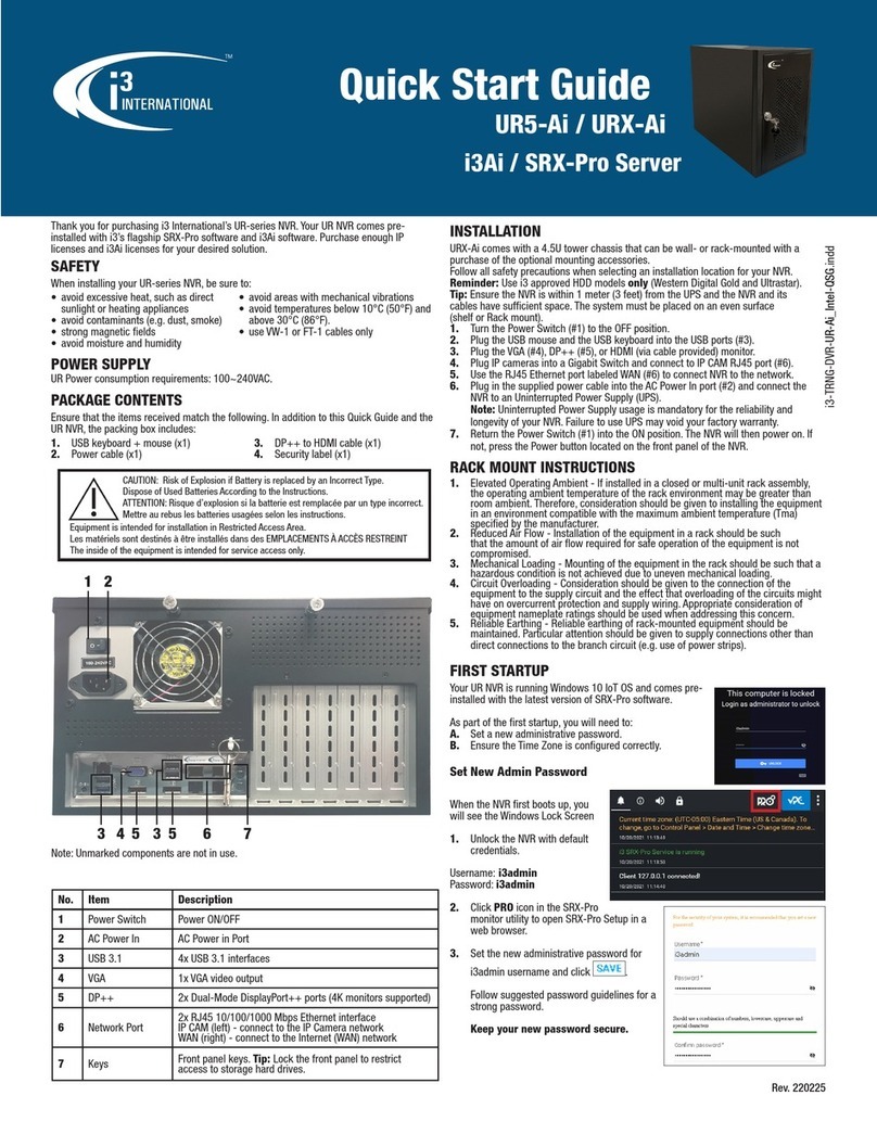
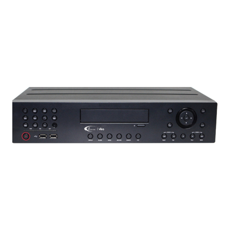
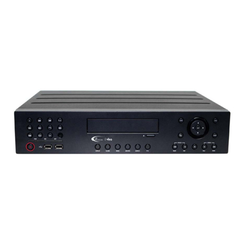
i3 International VEO 16 User manual

Quick Operation Manual
©2014 i3 International Inc.
The contents of this user manual are protected under copyrights and computer program laws.
16
VEO
EMBEDDED DVR
Rev. 141112 v.1.3

i
Table of Contents
Installation................................................................................................................................................................................ 1
Precautions .......................................................................................................................................................................... 1
Accessories .......................................................................................................................................................................... 2
Rear View............................................................................................................................................................................ 3
Basic Layout......................................................................................................................................................................... 4
Installation Instructions ......................................................................................................................................................... 4
PC Connection on Local Network ........................................................................................................................................... 6
PC Connection on Remote Network ....................................................................................................................................... 8
PTZ Camera Connection (RS-485) .........................................................................................................................................10
Alarm I/O Connection ...........................................................................................................................................................11
Getting Started ........................................................................................................................................................................12
Front View..........................................................................................................................................................................12
Log In.................................................................................................................................................................................13
Log Out...............................................................................................................................................................................13
System Shutdown ...............................................................................................................................................................13
Live Screen .........................................................................................................................................................................14
Viewing Live Video..........................................................................................................................................................15
Timeline..............................................................................................................................................................................16
Status Bar...........................................................................................................................................................................16
View Event Log...............................................................................................................................................................17
Quick Menu.........................................................................................................................................................................19
Digital Zoom...................................................................................................................................................................19
Instant Snapshot Export...................................................................................................................................................20
PTZ Mode................................................................................................................................................................................25
Preset Recall .......................................................................................................................................................................27
Creating New Presets ..........................................................................................................................................................27
Preset Scan ....................................................................................................................................................................28
Preset Tour.....................................................................................................................................................................29
Video Search............................................................................................................................................................................31
Search Window...................................................................................................................................................................31
Playback Window................................................................................................................................................................33
Video Export ............................................................................................................................................................................34
Exported Video Playback ......................................................................................................................................................37

Table of Contents
ii
Using Veo16 Backup Player .............................................................................................................................................37
Using Windows Media Player...........................................................................................................................................41
Recording Setup.......................................................................................................................................................................43
Auto Configuration Mode .....................................................................................................................................................44
Size/FPS/Quality Settings .................................................................................................................................................45
Motion Sensor .........................................................................................................................................................................48
Sensitivity Level...................................................................................................................................................................49
Motion Detection Area.........................................................................................................................................................49
Web Viewer.............................................................................................................................................................................51
IP Address Information.........................................................................................................................................................51
Connecting via Web Browser................................................................................................................................................53
Search Video via Web Viewer...............................................................................................................................................56
Export Video via Web Viewer................................................................................................................................................58
Setting Destination Folder................................................................................................................................................58
Exporting AVI video.........................................................................................................................................................59
Exported AVI Video Playback............................................................................................................................................60
Troubleshooting (FAQ) ..............................................................................................................................................................62
Specifications...........................................................................................................................................................................63

Veo16 –User Guide
1
Installation
Thank you for purchasing an i3 Veo16 digital video recorder.
In order to function properly and to its full potential, i3 Veo16 unit must be located in a clean dust free room and a well ventilated area
with consistent temperatures within the acceptable range of 20-25° Celsius. The acceptable temperature range must be maintained for
the stability of the DVR. Operating Relative Humidity in the server room should be 20% to 80% (non-condensing). In addition, an
uninterrupted power supply (1000 VA) with a constant power of 118 to 120 AC must be used with each DVR. If the installation
environment does not meet the conditions above, there is a risk of system malfunction.
i3 International will only warranty its products if the installation environment meets the conditions above. Should the environmental
conditions be not met, the DVR warranty will be voided. i3 International highly recommends cleaning the DVR filter regularly to facilitate
the proper ventilation and normal air flow inside the unit (if available with your unit). The internal temperature of the units with unclean
filters is always higher, which often leads to overheating.
If the system needs to be modified or repaired, contact a certified i3 International Dealer/Installer. When serviced by unauthorized
technician, the system warranty will be voided. Should you have any problems or questions regarding our products, contact your local i3
International Dealer/Installer.
Precautions
Installation and serving should be performed only by qualified and experienced technicians to conform to all local codes and to maintain
your warranty.
Read and keep the instructions for future reference.
When installing your Veo16 digital video coder be sure to avoid:
excessive heat, such as direct sunlight or heating appliances
contaminants such as dust and smoke
strong magnetic fields
sources of powerful electromagnetic radiation such as radios or TV transmitters
moisture and humidity
areas with mechanical vibrations
fluorescent lamps or objects that reflect light
unstable light sources as this may cause flickering
temperatures below -10° Celsius or 14° Fahrenheit and above 50° Celsius or 122° Fahrenheit.
CAUTION: RISK OF EXPLOSION IF BATTERY IS REPLACED BY AN INCORRECT
TYPE.
DISPOSE OF USED BATTERIES ACCORDING TO THE INSTRUCTIONS.
BEFORE INSTALLATION:
Installation should be carried out only by qualified personnel and in accordance with any electrical regulations enforced at the
time.
The DVR must be placed on a stable surface or mounted in an approved cabinet.
Adequate ventilation must be provided, take care not to block any of the air vents on the DVR.
Adequate protection against lightning strikes and power surges must be installed to prevent damage to the DVR.

Installation
2
If cleaning is necessary, shutdown the DVR and disconnect power first. Use a soft dry cloth only. Never use any abrasive
cleaners.
Do not attempt to service or repair the DVR as opening or removing covers may cause static damage to the inner DVR
components. Refer all servicing to qualified service personnel.
Accessories
If any parts are missing or damaged, contact the dealer you purchased the DVR from. The DVR packing box includes, in addition to this
manual (User Manual CD),
Figure 1.1. Veo16 Accessories
1. Power Cable x1.
Connect one end to 12V DC Power Adapter (#2 in Figure 1.1) and the other end to the UPS (Uninterrupted Power Supply). Plug in the UPS
into the power outlet.
IMPORTANT: Without the use of UPS, the unit warranty is void.
2. 12V DC Power Adapter x1.
Plug in the Power Cable (#1) on one end, connect to the Power adapter cable (#3 in Figure 1.1) to the other end.
3. Power adapter cable x1.
Connect one end to the 12V DC Power Adapter (#2 in Figure 1.1), plug the other end into the 12V port on the back of your Veo16 DVR.
(#M on Figure 1.2)
4. Hard Drive screws x10.
Standard Veo16 DVR comes pre-installed with 1 x 1TB hard drive. If required, one additional hard drive can be installed i3 International
Dealer/Installer after purchase.
Use the screws to secure the additional drive, if using.
5. Power cable retainer clip.
Secure the power adapter cable (#2 in Figure 1.1) with the power cable retainer clip, then fasten retainer clip to the opening (#F on Figure
1.1). Securing the power cord with the retainer clip will help prevent unintended disconnection of the power from the Veo16 DVR.
6. USB Mouse x1.
Plug in the USB mouse into one of the USB ports for easy system navigation (#K in Figure 1.1 and #16 in Figure 2.1)
7. Remote Control x1.
Veo16 Remote control can be used to operate the DVR as an alternative to USB mouse and the front panel buttons.
8. AAA batteries for the Remote Control x2
Install 2 AAA batteries into your Veo16 DVR remote control before using.

Installation
3
Rear View
Figure 1.2. Veo16 DVR, rear view.
No.
Name
Description
A
VIDEO IN
BNC camera input. Connect up to 16 analog camera inputs.
B
AUX
Connect the Main BNC Monitor.
SPOT OUT
Used for SPOT OUT monitor only.
Note: Use HDMI cable to connect the HD class monitor (I).
C
AUDIO IN
Connect up to 4 Audio Inputs.
D
AUDIO OUT
Connect an Audio Output.
E
WAN (UPLINK)
Network port used to connect to the Internet, router or hub.
F
POWER CABLE
SECURE
Secure the power cable with the power cable retainer clip (#5 in Figure 1.1), then fasten retainer clip to the opening.
Securing the power cord with the retainer clip will help prevent unintended disconnection of the power from the
Veo16 DVR.
G
ALARM IN
Alarm Input signal port. Connect up to 4 alarm inputs.
RELAY
Relay Terminal output port. Connect up to 2 relay outputs.
RS485
Communication port for PTZ camera.
H
VGA
Connect VGA monitor video output.
I
HD-MONITOR
Connect 1080p 60Hz HDMI video monitor.
Note: Your monitor must support 1920 x1080 at 60Hz when DVR is set to NTSC standard and 1920 x 1080 at
50Hz/60Hz when DVR is set to PAL standard.
J
eSATA
Connect external eSATA storage.
K
USB
Connect USB mouse or USB storage.
L
NTSC/PAL DIP
Switch
Use to set Video Standard (NTSC/PAL). If the unit is set to NTSC standard, all connected analog cameras must also
support/be set to NTSC standard.
M
DC 12V
Connect Power Adapter Cable (included, #3 in Figure 1.3).

Installation
4
Basic Layout
Figure 1.3. Veo16, Basic Layout. Connecting peripheral devices to your Veo16 DVR.
Installation Instructions
IMPORTANT: The use of UPS (Uninterrupted Power Supply) is mandatory to
maintain DVR warranty.
Before installation:
Ground Yourself. This will remove any static electrical charge your body might be carrying.
Connect the peripheral devices by following the instructions below.
Step 1.
Plug in the USB mouse into the USB port in the front or the back of the unit.
Step 2.
Plug in your monitor. Depending on the monitor model, use either HDMI or a VGA port on the back of the unit. To connect a DVI monitor,
use HDMI-DVI adapter (not included).
Note: For proper display, your monitor must support 1920 x1080 at 60Hz.
Step 3.
Connect analogue cameras to the VIDEO IN BNC video ports #1-16.
Step 4.
Connect RS485 communication cable for PTZ cameras to the corresponding ports on the back of the DVR, if using.

Installation
5
Step 5.
Connect other peripheral devices, such as Spot Out and/or
Auxiliary BNC monitors, BNC Audio Inputs/Output, Alarm Inputs,
Relay Outputs, or eSATA storage, if using.
Step 6.
Connect the Internet cable to WAN port on the back of the DVR,
if applicable.
Step 7.
Set the NTSC/PAL dip switch to your video standard, if
applicable.
Step 8 (see Fig. 1.4).
Connect Veo16 DVR to the Power Source.
a. Connect the Power Adapter Cable to the DC 12V port
on the back of the Veo16 DVR.
b. Connect the 12V DC Power Adapter to the Power
Adapter Cable.
c. Connect the Power Cable to the DC 12V Power
Adapter.
d. Connect the Power Cable to the UPS (Uninterrupted
Power Supply). The use of the UPS is mandatory to
maintain DVR warranty.
e. Connect the UPS to the Power Source / power outlet.
f. Secure the power cable with the power cable retainer
clip (#5 in Figure 1.1), then fasten retainer clip to the
opening on the back of the Veo16 DVR (#F in Figure
1.2).
Securing the power cord with the retainer clip will
help prevent unintended disconnection of the power
from the Veo16 DVR.
Once Veo16 DVR is connected to the power source, it will power
on. If it does not, press the Power button on the DVR's front
panel.
Figure 1.4.
Connecting Veo16 DVR to the Power Source

Installation
6
PC Connection on Local Network
Veo16 DVR can be accessed from desktop PC on a Local Area Network (LAN). This allows viewing live or recorded DVR video, exporting
saved video clips and adjusting settings from multiple local PC stations.
Figure 1.5. Local PC connection to the Veo16 DVR on LAN, topography diagram
Figure 1.6. Local PC connection to the Veo16 DVR on LAN, connection diagram

Installation
7
To access Veo16 DVR remotely via Web Browser on a local network, follow instructions below:
1. Connect one end of a network cable to the WAN (UPLINK) port on the back of the DVR (#E in Figure 1.2) and the other end to
the broadband router or a hub.
Note: Do NOT use LAN (DOWNLINK) port.
2. Connect the local PC to the broadband router or hub. Use diagram Figure 1.6 above as a guide.
3. Open the web Browser window on the connected local PC. Enter the Veo16 IP address into the address bar of your Web
Browser in this format: "http://IP Address:8080). The DVR Web Service Port is set to Port 8080 by default but can be changed
in the DVR's Network Setup screen. Refer to Network Setup section of this manual.
E.g. http://192.0.0.150:8080
4. In the Windows Security login window, enter Veo16 Login and Password.
Important: Veo16 login and password information is case-sensitive.
Note: Factory Default Login: ADMIN, Password: 1234. For Security purposes, it is highly recommended that you change the
factory default administrative password after the initial login. You can change administrative password, add and remove DVR
users in System Setup -> User Management screen. Refer to User Management section of this manual.
5. The first time you connect to the Veo16 over the local network, your web browser may ask you to install a required Add-on.
Click on the pop-up menu below the address bar, and select "Install This Add-on for All Users on This Computer..."
option.
6. In the next window, click Install.
Your Veo16 DVR can now be controlled via Web Browser.

Installation
8
PC Connection on Remote Network
Veo16 DVR can be accessed from desktop PC on a Wide Area Network (WAN). This allows viewing live or recorded DVR video, exporting
saved video clips and adjusting settings from multiple remote PC stations.
Figure 1.7. Remote PC connection to the Veo16 DVR on WAN, topography diagram
Figure 1.8. Remote PC connection to the Veo16 DVR on WAN, connection diagram

Installation
9
1. Connect one end of a network cable to the WAN (UPLINK) port on the back of the DVR (#E in Figure 1.2) and the other end to
the broadband router or a hub.
Note: Do NOT use LAN (DOWNLINK) port.
2. Connect the ADSL modem, if using, to the WAN port on the broadband router or hub.
3. Connect the local PC to the broadband router or hub. Use diagram Figure 1.7 as a guide.
4. If using the router, set the port forwarding.
5. On the remote PC, open the Web Browser window and enter the Veo16 DDNS address into the address bar in this format:
"http//DVRNAME.dvrlink.net:8080". The DVR Web Service Port is set to Port 8080 by default but can be changed in the DVR's
Network Setup Screen.By default, DVRNAME is set to the Veo16 MAC Address but can be changed to a custom value in the
DVR's Network Setup Screen.. E.g. "http://00115f123456.dvrlink.net:8080" OR "http://veo16.dvrlink.net:8080", where DVR
NAME value has been set to "veo16" in the Network Setup screen.
Refer to Network Setup section of this manual for more information on changing DVR's DDNS name and/or Server Port.
6. In the Windows Security login window, enter Veo16 Login and Password.
Important: Veo16 login and password information is case-sensitive.
Note: Factory Default Login: ADMIN, Password: 1234. For Security purposes, it is highly recommended that you change the
factory default administrative password after the initial login. You can change administrative password, add and remove DVR
users in System Setup -> User Management screen. Refer to User Management section of this manual.
7. The first time you connect to the Veo16 over the local network, your web browser may ask you to install a required Add-on.
Click on the pop-up menu below the address bar, and select "Install This Add-on for All Users on This Computer..."
option.
In the next window, click Install.
Your Veo16 DVR can now be controlled via Web Browser.

Installation
10
PTZ Camera Connection (RS-485)
In order to connect and operate your PTZ camera through Veo16 DVR, follow instructions below:
1. Ensure your PTZ camera is connected to the appropriate power supply.
2. Connect the RS485 wires from the PTZ camera to the corresponding RS485+ and RS485- ports on the back of Veo16 DVR,
see diagram below. (#G in Figure 1.2)
3. Plug in the BNC video cable from the PTZ camera into one of the VIDEO IN ports on the back of Veo 16 DVR, see diagram
below (#A in Figure 1.2).
4. Configure correct PTZ Camera Address, Protocol and Baud Rate according to the PTZ Camera specifications in System Setup -
> Camera -> PTZ Setup screen and click Apply.
Refer to PTZ Mode section of this manual for more information.
5. Veo16 supports the following PTZ Protocols:
1. PELCO-D
2. PELCO-P
3. MESA-DOME
4. D-Max
5. FastraxII_2
6. Ganz_PT_V3_2
7. SCC_641
8. SCC_643a
9. Spd_3300
10. Multix
11. MRX_1000
12. WV-cs850
13. WV-crs604
14. PTC-400c
15. PTC-200
16. TAKEX
17. LPT-A100L
18. interM
19. VITEK
20. LILIN
21. MAXPRO
22. VCL
Figure 1.9. Veo16 System Setup -> Camera -> PTZ Setup screen

Installation
11
Alarm I/O Connection
Figure 1.10. Veo16 rear, Alarm In/Out terminals
Veo16 DVR supports up to 4 Alarm In (Sensor) sensor devices, (such as motion sensor, for
example) and up to two Alarm Out/Relay control devices.
To connect an alarm input device such as sensor to the rear [ALARM IN] port of Veo16 DVR,
follow instructions below:
1. Use a pointed object, such as a screw driver to push the top orange portion of the
desired Alarm IN (IN1, IN2, IN3, IN4) and GND terminals in.
2. While pushing, insert one end of the alarm signal cable into the desired ALARM IN
terminal opening.
3. While pushing, insert one end of the alarm ground cable into the GND terminal
opening.
4. Release the orange portion of the terminal and gently pull on the cables to ensure
proper and secure connection. If the cable dislodges, repeat steps 1-3, this time
inserting the cable further inside the terminal.
5. To remove the alarm input cable, use a pointed object to push the top orange portion of the corresponding terminal inwards,
while pulling gently on the cable.
To connect a relay device such as a normally-open (NO) or normally-closed (NC) control device to the rear [ALARM IN] port of Veo16
DVR, follow instructions below:
1. Use a pointed object, such as a screw driver to push the top orange portion of the desired RELAY (NO1, NC2) and
corresponding ground COM (COM1, COM2) terminals in.
2. While pushing, insert one end of the signal cable into the desired RELAY terminal opening (NO1/NC1)
NO (Normally Open) - relay is in Open position by default, but switches to Closed position when an alarm event
occurs.
NC (Normally Closed) - relay is in Closed position by default, but switches to Open position when an alarm event
occurs.
COM - relay ground wire terminal.
3. While pushing, insert one end of the signal cable into the COM terminal opening.
4. Release the orange portion of the terminal and gently pull on the cables to ensure proper and secure connection. If the cable
dislodges, repeat steps 1-3, this time inserting the cable further inside the terminal.
5. To remove the relay output cable, use a pointed object to push the top orange portion of the corresponding terminal inwards,
while pulling gently on the cable.
Figure 1.11. Veo16 rear, Alarm
In/Out terminals, detail

Veo16 –User Guide
12
Getting Started
Front View
Figure 2.1. Veo16, Front Panel
No.
Name
Button
Description
1
POWER
Turn Veo16 Embedded DVR ON or OFF
2
DISPLAY
Click to switch between various available display modes in Live and Playback modes.
3
SEARCH
Open the Search Mode window
4
MENU
In Live Mode, open the Setup menu
5
PTZ/FOCUS
In Live Mode, open the PTZ Control window
6
Channel Selection
Buttons
Press to display the corresponding video channel in Live and Playback modes.
Use I+ button to enter camera double-digit video channel numbers (10 and up). The
numbered buttons are also used to enter numeric passwords in the login screens.
7
Cursor Keys
▲▼◄►
Use cursor keys to navigate various system menus.
8
ENTER
Apply or select an item in the menu.
9
RETURN
Cancel an operation or return to the previous menu / screen.
10
Shuttle Wheel
Quickly adjust playback direction and speed. Also used to control camera Zoom when in PTZ
mode.
11
JOG
Use in Playback mode to move footage forward / backward, frame-by-frame
12
HOLD
Lock the current function of the Shuttle Wheel so it can be released.
13
Fast Rewind
◄◄
Increase reverse playback speed
14
Pause/Resume
▌▌
Pause / resume
15
Fast Forward
►►
Increase video playback speed
16
USB Ports x2
Connect USB mouse or USB storage
17
CD/DVD Eject
Button
Press to eject the CD-ROM tray

Getting Started
13
Log In
1. Upon start up, the login screen will be displayed
2. Select the user ID from the drop-down menu and enter the password in the corresponding field.
The default user ID is "ADMIN", the default password is "1234".
3. Click OK
For security purposes, it is recommended to change the administrator password after the first login.
Log Out
To prevent unauthorized access, it is recommended to log out of the DVR when not in use.
1. Hover the mouse cursor near the bottom of the Live screen to display the Status Bar.
2. Click on the MENU button and select LOG OUT from the list.
System Shutdown
To shut down Veo16 DVR, follow instructions below:
1. Position your mouse cursor in the bottom left-hand corner of the screen to bring up the Status Bar.

Getting Started
14
2. Click on the MENU button and select SHUTDOWN from the list.
3. Use the virtual keyboard to enter the password.
4. Click OK to shut down Veo16 DVR.
Note: Shutting down the DVR in an unsafe manner, such as removing the power cord while the system is in operation, may result in
corrupt hard drive sectors, data loss and shortened hard drive life cycle.
Live Screen
Live Screen consists of Live View, Quick Menu, Timeline and Status Bar.

Getting Started
15
Viewing Live Video
After logging in, you will be able to view live video from all connected cameras in a multi-screen view.
Where camera is out of order, black screen will be displayed with text “VIDEO LOSS”.
Call your installer for service if a previously working camera can no longer be seen in the Live view screen.
In the example below, video loss has been detected on Channels 15 and 16.
To bring a specific camera screen into full screen mode, position your mouse cursor over the camera video stream on the screen and
double-click the left mouse button. The camera will be maximized on the screen.
Double-click on the screen again to return to the multi-screen display.

Getting Started
16
Timeline
Double-click on the timeline to switch to the Playback mode. Highlight a portion of the timeline, right-click and select EXPORT TO,
to create a CD/DVD backup of the selected video clip.
See Video Export section for additional info.
Item
Function
Timeline Date
Displays the date of the current timeline. Click to select a different recording date to
display in the timeline.
Zoom in/out the
Timeline
Expand or minimize the timeline.
Navigation through
Timeline
Move to the previous or next section of the timeline. Alternatively, use the mouse
wheel to scroll between different sections of the timeline.
Timeline Recording
Bars
The orange text represents the month and date: MM-DD. Gray text represents the
time of the day in military time, where 15:00 stands for 3:00PM.
The colored bars represent the recorded data. The color indicates the type of the video
recording:
- Lime: Pre-recording. To configure pre-recording, click the MENU button, select
RECORD SETUP from the menu, then select OPERATION MODE. See Record Setup
section for more information.
- Green: Continuous
- Red: Alarm
- Blue: Motion
- Yellow: Panic
Double-click on the timeline to launch the Playback mode queued up to the selected
time and date. In this example, the Playback mode will display video recorded on July
10, 2014 at 3:00PM.
Status Bar
The buttons in the status bar on the screen provide quick access to the most commonly used features of the DVR.
To access Status Bar, hover the mouse cursor near the bottom of the screen to display it.
Status Bar Icon
Function
Displays the main menu window. Select "Search, Archiving, System Setup, Record Setup, Log Out
or Shutdown" from the list.
Displays the User ID of the currently logged in user.
Show/Hide the Status Bar. When hidden, the Status Bar can still be accessed by hovering the
mouse over the status bar/timeline.
Select one of the four screen modes: Full screen, Quad, 3x3 or 4x4 split screen division.

Getting Started
17
Status Bar Icon
Function
Activate Auto Sequence mode. Sequencing can be configured under MENU -> SYSTEM SETUP -> DISPLAY ->
SEQUENCE menu.
Display or hide the OSD menus on the screen.
Switch to the PTZ screen mode, where you can control your connected and configured PTZ cameras, create
Presets and configure PTZ Scan/Tours. Refer to PTZ Mode section of this manual for more information.
Switch to the Digital Zoom screen mode, where you can digitally zoom into live video image on the selected
video channel.
Displays the event log of the recent recording events. Double-click a desired log entry to display the video linked
to the event in the Playback screen.
Activate this icon to listen to the audio from the selected video channel. Audio output (e.g. speaker) must be
connected to the unit.
Initiate emergency/panic recording.
Icon blinks after pre-configured event occurs. Click on the icon to view details of the event. Event categories
include motion sensor, video loss, system event, tamper event. To configure an event, open MENU -> SYSTEM
SETUP -> EVENT setup.
/
Displays network connection status and information, such as IP Address, MAC Address, DDNS Address, RTSP
Service port, Web Service Port, and External IP Address, as well as the list of remote clients currently logged
into the unit via remote PC. This information is for display purposes only.
To learn how to make changes to network settings, please refer to Network Setup section of this manual.
Displays the disk space information. "OW" is displayed when the DVR switches to Overwrite mode (if
configured).
Displays current date/time.
View Event Log
To view the list of the events that have occurred in the past hour, click the Event Log button in the Status Bar. To access the
Status Bar, hover the mouse cursor near the bottom of the screen to display it.
Event Log window will be displayed with a list of recent events.
The list consists of the event logs generated in the past hour and is constantly being overwritten by newer events.
To view the video linked to the log event, double-click a desired log record in the list.
Other manuals for VEO 16
1
Table of contents
Other i3 International DVR manuals

i3 International
i3 International SBB41 User manual

i3 International
i3 International SRX-Pro Series User manual

i3 International
i3 International VEO48016 User manual

i3 International
i3 International SRX-Pro Series User manual

i3 International
i3 International U12 User manual

i3 International
i3 International Veo 12016N User manual

i3 International
i3 International UR5-Ai User manual

i3 International
i3 International Veo 48016 User manual

i3 International
i3 International ANNEXXUS Ax516 User manual

i3 International
i3 International Veo16p User manual