manuals.online logo
Brands
  1. Home
  2. •
  3. Brands
  4. •
  5. i3 International
  6. •
  7. Security Camera
  8. •
  9. i3 International Am42 Series User manual

i3 International Am42 Series User manual

User Manual
i3-TRNG-CAMS-Am42R-UM.indd Rev. 161123
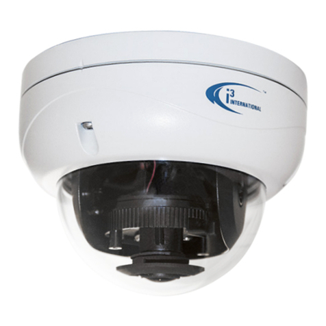
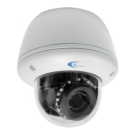
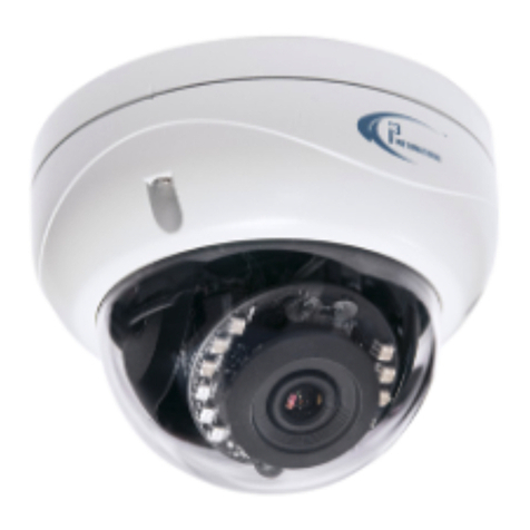
HD720P (1MP) Vandal-Proof Infrared Dome Camera Am42 Series
The Am42 indoor/outdoor series cameras include the Am42R and the Am42RB.
• Am42R comes in white. • Am42RB comes in black.
SAFETY
When installing your Am42 Series camera be sure to avoid:
• excessive heat, such as direct sunlight or heating appliances
• contaminants such as dust and smoke
• strong magnetic fields
• moisture and humidity
• areas with mechanical vibrations
• fluorescent lamps or objects that reflect light and unstable light sources
• temperatures below -30° C (-22° F) and above 60° C (140° F).
• To avoid electrical shock and to preserve the product warranty, DO NOT disassemble
the camera. Refer servicing to qualified personnel only.
POWER SUPPLY
Ensure the supplied voltage meets the power consumption requirements of this camera
before powering the camera on. Incorrect voltage may cause irreparable damage to the
video camera and will effectively void the camera warranty.
This camera series accepts DC 12V and AC 24V power.
CLEANING
• For maximum optical clarity, the camera dome or lens must remain clean. Use a soft,
dry cloth to remove finger prints or dust from the dome cover.
• Use a blower to remove dust from the lens.
• Do not use volatile solvents such as alcohol, benzene, or thinners, as they may
damage the surface finishes.
PACKAGE CONTENTS
In addition to this manual and a fully assembled camera, the product box includes:
1. Security Torx bit x1
2. Plastic Anchor x4
3. Round Head Screw (Tapping Type) x4
4. Spot monitor auxiliary video output
cable x1
5. Surface Mount template x1
1. 3-axis camera module / second housing.
2. Long screws (pre-installed) for attaching camera module to the back box, x3
3. Lens.
4. IR board.
5. Lens focus adjustment w/ locking screw (Far / Near).
6. Lens zoom adjustment w/ locking screw (Tele / Wide).
7. Joystick (for on-screen camera menu control).
8. Dip switch (CVBS / TVI output). Remove the Shroud/Liner for easy access.
9. 2-pin Service (spot) monitor output.
10. Power connector (12DC / 24AC).
11. TVI High-definition analog video connector (1MP. 1280x720 = 720P).
To use high-definition analog stream (1MP), the camera must be connected to
i3’s HR16 encoder or standalone Veo17 DVR. Put the Dip switch (#7) into the “TVI”
position to enable TVI video stream.
12. CVBS standard-format analog video connector (4CIF = 720x480). Can be
connected directly to the BNC board on the i3’s HVR units. Put the Dip switch (#7)
into the “CVBS” position to enable composite video stream.
13. Lexan Bubble (Dome).
14. Inner liner / Shroud (Removable for convenient lens position adjustments).
15. Screws attaching camera bubble to the camera module (x3 silver).
16. Camera’s back box. Compatible with i3’s DB60/DB60B Goose-neck bracket. Can
also be used for pendant mount installations.
17. Side conduit hole (3/4”).
Remove plug to route power and video cables through the side opening.
Use the plug for the top conduit hole in that scenario.
When using outdoors, sealant must be used to maintain the IP66 status.
18. Top conduit hole (3/4”). Can also be used for pendant mount installations.
When using outdoors, sealant must be used to maintain the IP66 status.
19. Mounting holes, partially drilled, x6 (complete drilling the holes prior to
installation).
CAMERA PARTS AND DEFINITIONS
1
3
5
6
10
11
12
7
8
9
CVBS
TVI
13
15
16
19
17
18
14
1MP
720x480
4
4
12 3 5
Lens Direction
GUIDE PATTERN
HIGH-DEFINITION ANALOG VIDEO SUPPORT
Your Am42 series camera supports both the standard composite analog video stream
(720x480) and a HD-TVI - high-definition TVI video stream (1MP).
Only one type of video stream may be used at-a-time.
To use the camera’s HD-TVI stream (1MP), the user must set the on-board dipswitch to TVI
mode and then connect the camera’s gray BNC cable connector (labeled 1MP) to i3’s HR16
video encoder or standalone Veo17 DVR.
Important: HD-TVI stream will NOT be supported if the camera is connected directly to
i3’s HVR unit. When connecting to i3 DVMS directly, set the on-board dipswitch to CVBS
mode and connect the camera’s black BNC cable connector (labeled 720x480) to the
DVMS’ BNC board or BNC fly-out cable.
UP
2
2
USER MANUAL
Page -2-
Am42 Series Analog Dome Camera
UP
Focus Lever +
locking screw
(Far/Near)
F N
Zoom Lever +
locking screw
(Tele/Wide)
T W
INSTALLING THE CAMERA
Prepare the mounting surface.
• Depending on the type of
installation, additional mounting
accessories may need to be
purchased.
• It is the installer’s responsibility
to ensure that the mounting
surface is suitable for the chosen
installation method.
• Based on installation location and
surface type, supplied screws and anchors
may not be adequate. Mounting hardware
is site-specific and may need to be supplied by the
installer.
SURFACE MOUNTING
1. Use the supplied security Torx key to loosen three
screws securing the dome bubble housing to camera
module. Gently pull the dome bubble away from the
main camera module.
2. Temporarily remove the camera liner/shroud for
3-axis Range Limitations:
Pan:
0 - 355°
Tilt: 0 - 75°
Rotation: 0 - 355°
three long machine-type screws pre-inserted
into the camera module.
10. Connect camera to 12DC or 24AC power
and attach the service monitor to the 2-pin
connector on the camera.
11. Adjust the lens angle by panning and tilting the
camera lens assembly and rotating the camera
lens base. Do not over-rotate the camera lens
beyond the stop point to avoid damage to the
camera.
CVBS / TVI
dipswitch
2-pin Service
Monitor
connector
13. Use the joystick on the camera board to adjust any additional camera settings (e.g.
image brightness, colour or contrast, day/night mode, etc.).
See CAMERA MENU
section for more information on camera’s on-screen menu.
Set the video format dip switch to the desired setting:
CVBS (standard composite video, 720x480) or
TVI (high-definition video, 1MP). Depending on the dip switch
selection, the matching BNC video connector will be enabled on
the camera.
IMPORTANT: In order to be able to use high-definition video,
Joystick
your Am42R camera must be connected to i3’s HR16 video encoder or
standalone Veo17 DVR.
If connecting directly to the HVR’s / DVR’s BNC panel, set the dip switch to CVBS to
camera’s inner liner (shroud) until it snaps back into place.
15. Replace the camera dome bubble and tighten the 3 silver screws securing the
dome bubble to the camera base.
FLUSH MOUNTING
Am42 Series cameras can be flush mounted with the use of i3’s flush mounting kit
(Part # AM42FM for the AM42R and the AM42FMB for the AM42RB, sold separately).
When flush-mounting the camera, do not use the supplied camera back box.
Follow the mounting instructions supplied with the kit.
WALL MOUNTING w/ GOOSENECK BRACKET
12. Adjust the camera’s zoom and focus using
Zoom / Focus levers on the camera module.
Loosen the locking screws, adjust the lever
and re-tighten the locking screw when
desired view is achieved.
use 720x480 composite video cable.
14. Once the desired view is achieved, unplug the service monitor and replace
Am42R
Back Box
DB60
Gooseneck
Bracket
Use silicone
to maintain
IP66 rating
3/4” Rigid
Pipe
3/4” Electrical
EMT Conduit
Fitting
Use silicone
to maintain
IP66 rating
Am42R
Back Box
Am42R camera can be wall-mounted with the
use of i3’s gooseneck wall bracket (Part # DB60
for the Am42R and DB60B for the AM42RB
sold separately). Together with the optional
DB60CPM/DB60CPMB bracket, DB60/DB60B
gooseneck bracket has the capability of being
corner- or pole-mounted.
Follow the mounting instructions supplied
with the DB60/DB60B bracket.
Attach the top conduit hole of the camera’s back
box to the threaded end of the DB60/DB60B bracket and
rotate clockwise to attach the two together. Use silicone sealer to maintain IP66 rating
when installing outdoors.
Complete installation as for Surface Mounting from Step #8 onwards.
PENDANT POLE MOUNTING
Use a 3/4” Electrical EMT Conduit Fitting with a rigid
3/4” pipe for this type of installation.
Attach the top conduit hole of the camera’s back box
to the threaded end of the 3/4” Electrical EMT Conduit
Fitting and rotate clockwise to attach the two
together.
Use silicone sealer to maintain IP66 rating
when installing outdoors.
Complete installation as for Surface Mounting
from Step #8 onwards.
easier lens adjustment.
3. Depending on the type of installation and mounting
surface, complete drilling 2-4 holes in the back box
in preparation for the mounting.
4. Attach the supplied mounting template to the
mounting surface.
5. Drill holes, as marked on the template and insert
supplied anchors into the holes. The number and
positioning of holes must match the ones pre-
drilled on the back box in Step 4.
6. Drill the conduit hole for the camera
cable, as marked on the template,
if using the top conduit hole to
route cables. Skip this step if
using the side conduit hole.
7. Use three tapping screws provided
to secure the camera’s back box to
the prepared mounting surface.
8. Feed the camera cables through the
selected conduit hole. Use silicone sealer
around the chosen conduit hole to maintain IP66 rating when installing the Am42R
outdoors.
9. Use the supplied security Torx key to attach the camera module to the back box. Use
USER MANUAL
Page -3-
Am42 Series Analog Dome Camera
MENU
VIDEO
STANDARD MAIN MENU VIDEO
RATIO
SAVE & EXITCONTRASTCOLORAUTO
BRIGHTNESS
SHARPNESS
MASKING
B/WMANUAL
AE MODE
COLOR GAIN
ZOOM IN
SMART
AGC
3D NR
SENSE UP
MIRROR
AE RESET
VIDEO
SETTINGS FUNCTION
DAY &
NIGHT
WB
CAMERA MENU > MAIN MENU > AE
Under AE (Automatic Exposure) sub-menu, configure the video image BRIGHTNESS, AE
MODE, AGC, and SENSE UP.
BRIGHTNESS: Set the video image brightness value from 1 to
10, where 10 represents the highest brightness setting.
AE MODE: Set the Automatic Exposure to GLOBAL AE or DWDR
(Digital WDR)
AGC: Set the Automatic Gain Control to HIGH, MIDDLE or LOW.
Set to OFF to disable AGC function.
SENSE UP: Sense Up function allows the user to select a slower shutter speed in order to
let extra light into a camera. This provides higher sensitivity in low light conditions. Set the
Sense Up value from 0 to 16.
AE
1. BRIGHTNESS ----|-8
2. AE MODE DWDR
3. AGC OFF
4. SENSE UP --|--10
5. RETURN
CAMERA MENU > MAIN MENU > WB
Under WB (White Balance) sub-menu, set WB setting to either AUTO or MANUAL mode.
AUTO: Set to AUTO to adjust White Balance automatically
MANUAL: Set to MANUAL to configure R GAIN / B GAIN values.
Set between 1 and 10.
WB
1. R GAIN --|--5
2. B GAIN --|--5
3. RETURN
CAMERA MENU > MAIN MENU > DAY & NIGHT
Under DAY & NIGHT sub-menu, set the camera to either COLOR, B/W or SMART (auto) DAY
& NIGHT mode.
COLOR: Set the camera to COLOR mode to keep the camera permanently in the daytime
(colour image) mode.
B/W: Set the camera to B/W mode to keep the camera permanently in the nighttime
(black-and-white video image) mode.
SMART: Set the camera to SMART mode to enable/disable
the camera’s IR LEDs (INFRARED LAMP). Set the SMART IR
level value between 1 to 5.
SMART
1. INFRARED-LAMP OFF
2. SMART-IR --|--2
3. RETURN
CAMERA MENU > MAIN MENU > VIDEO SETTING
Under VIDEO SETTINGS sub-menu, set the camera’s video image settings, including
CONTRAST, SHARPNESS, COLOR GAIN, 3D NR and MIRROR.
CONTRAST: Set the CONTRAST value from 1 to 10, which 10 being the highest
contrast.
SHARPNESS: Set the sharpness for EDGE and DETAIL value from 1 to 10.
COLOR GAIN: Set the COLOR GAIN value from 1 to 10.
3DNR: 3D Noise Reduction function removes image noise from static and moving video
images. Set 3D NR value to HIGH, MIDDLE or LOW. Set to
OFF to disable 3D NR function.
MIRROR: Mirror function flips the video image on the
screen. Set the MIRROR value to OFF, H, V or HV.
> Off: Do not use this feature
> H: flip images horizontally, left to right.
> V: flip images vertically, upside-down.
> HV: flips both horizontally and vertically.
CAMERA MENU > MAIN MENU > FUNCTION
Under FUNCTION sub-menu, set MASKING and ZOOM IN functions.
Define AREA: Configure settings for up to 4 separate Areas. Set the status to OFF/
ON to disable/enable. Set the area border colour to WHITE, YELLOW, CYAN, GREEN,
MAGENTA, RED, BLUE, or BLACK. Use the joystick (Up/Down/Left/Right) to set the area’s
horizontal and vertical size and position.
Set the HORIZON SIZE / MOVE value in increments of 10 - from 0 to 720 (if using CVBS)
or 0 to 1280 (if using HD-TVI).
Set the VERTICAL SIZE / MOVE value in increments of 10 - from 0 to 480 (if using CVBS)
or 0 to 720 (if using HD-TVI).
Define Area
1. AREA NO.0
2. AREA NO.1
3. AREA NO.2
4. AREA NO.3
5. RETURN
AREA
1. STATUS HIGH
2. COLOR WHITE
3. HORIZON SIZE 0
4. VERTICAL SIZE 0
5. HORIZON MOVE 0
6. VERTICAL MOVE 0
7. RETURN
MASKING: Set up to 7 separate privacy (masking) areas to block off areas of the
camera’s field of view. Set the background colour to WHITE, YELLOW, CYAN, GREEN,
MAGENTA, RED, BLUE, BLACK or MOSAIC. Note: Mosaic colour blurs video image.
Use the joystick (Up/Down/Left/Right) to set the area’s horizontal and vertical size and
position.
Set the HORIZON SIZE / MOVE value in increments of 10 - from 0 to 720 (if using CVBS)
or 0 to 1280 (if using HD-TVI).
Set the VERTICAL SIZE / MOVE value in increments of 10 - from 0 to 480 (if using CVBS)
or 0 to 720 (if using HD-TVI).
IMPORTANT: Video hidden behind the set Masking Area will be permanently lost.
ZOOM IN: Set the ZOOM IN value from 50 to 100 in increments of 10.
100 setting displays complete image and 50 setting shows a zoomed-in image.
CAMERA MENU > MAIN MENU > RESET
Reset all the settings to the default.
Save and Exit: Select SAVE to save the adjusted settings and exit the OSD Menu.
Select EXIT to discard all changes and exit the OSD menu.
MASKING
1. COLOR WHITE
2. AREA NO.0
3. AREA NO.1
4. AREA NO.2
5. AREA NO.3
6. AREA NO.4
7. AREA NO.5
8. AREA NO.6
9. AREA NO.7
10. RETURN
AREA
1. STATUS OFF
2. HORIZON SIZE 0
3. VERTICAL SIZE 0
4. HORIZON MOVE 0
5. VERTICAL MOVE 0
6. RETURN
CAMERA MENU > VIDEO RATIO
Select the Video Aspect Ratio. Select between 4:3 ratio or 16:9 ratio.
VIDEO SETTING
1. CONTRAST --|--5
2. SHARPNESS
3. COLOR GAIN --|--10
4. 3DNR HIGH
5. MIRROR HV
6. RETURN
Joystick
UP
CAMERA MENU
Use the camera’s on-board joystick to adjust
camera settings.
Use the button in the middle of the Joystick
to access the camera OSD MENU and confirm
selection. Move the Joystick in UP/DOWN/LEFT/
RIGHT directions to navigate within camera
menus.
UP
Press to access
camera menu
and to confirm
selection.
USER MANUAL
i3 INTERNATIONAL INC. 1.866.840.0004
www.i3international.com
Canada 780 Birchmount Road, Unit 16,
Scarborough, ON, M1K 5H4
U.S.A. 4450 Witmer Industrial Estates Unit 4
Niagara Falls, NY 14305
Am42 Series Analog Dome Camera
Rev. 161123
Specifications Am42R / Am42RB (HD720P Indoor/Outdoor Vandal Dome Camera)
Image System
Image Sensor 1.27 MP CMOS Image Sensor
Signal System NTSC/PAL
Effective Pixels (HxV) 1305(H) x 977(V)
OSD Yes
Aspect Ratio 4:3 / 16:9
Optical System
Focal Length (built-in lens) vari-focal, 2.8-12mm
F-stop Range (F-number) F1.4
Horizontal FOV (Field of View) 92° - 29.3°
Day/Night ICR
Electric
Digital Noise Reduction (DNR) 3D, Low/Middle/High/Off
Wide Dynamic Range (WDR) Digital
Min. Illumination 0.001 Lux @ (F1.2, AGC ON), 0 Lux with IR
S/N Ratio More than 62dB
Automatic Gain Control (AGC) Low/Middle/High/Off
White Balance Auto/Manual
Electric Shutter NTSC: 1/30 s to 1/50,000 s
PAL: 1/25 s to 1/50,000 s
Video Output (Selectable)
Note: Use one at-a-time. Must set on-board camera dipswitch. HD Video
Output works only with i3’s HR16 encoder
or standalone Veo17 DVR
.
CVBS Output: 1 x 1Vp-p Composite Output (75Ω/BNC)
HD Video Output: 1 x Analog HD output
Day/Night Mode Colour/BW/Smart IR
Other Features
Privacy Mask On/Off, maximum 8 zones
Other Sharpness, Brightness, Digital Zoom, Mirror, Reset
Mechanism
Angle Adjustment Pan: 0 - 355°, Tilt: 0 - 75°, Rotation: 0 - 355°
Dimensions Ø 147mm x 140mm (H) / Ø 5¾“ x 5½” (H)
Weight 0.9 kg (1.98 lb)
Protection Class FCC, CE, IP66, IK8, UL
IR
IR Distance up to 40 meters (131 feet)
Power SupplyF
Power Requirement DC 12V & AC 24V
Power Consumption Max. 5W
Environment
Operating Temperature -30° C - 60° C (-22° F - 140° F)
Operating Humidity 90% or less (non-condensing)
Warranty
Standard Warranty i3 Superior 3 year warranty

This manual suits for next models

1

Other i3 International Security Camera manuals

i3 International M77R2 User manual

i3 International

i3 International M77R2 User manual

i3 International Ax85 User manual

i3 International

i3 International Ax85 User manual

i3 International Ax63Z Series User manual

i3 International

i3 International Ax63Z Series User manual

i3 International Ax46 Series User manual

i3 International

i3 International Ax46 Series User manual

i3 International C-AX401D1M User manual

i3 International

i3 International C-AX401D1M User manual

i3 International Ax49D User manual

i3 International

i3 International Ax49D User manual

i3 International DB78BB User manual

i3 International

i3 International DB78BB User manual

i3 International Ax32VD14 User manual

i3 International

i3 International Ax32VD14 User manual

i3 International C-Di210 User manual

i3 International

i3 International C-Di210 User manual

i3 International Ax47R series User manual

i3 International

i3 International Ax47R series User manual

i3 International i3-B731 User manual

i3 International

i3 International i3-B731 User manual

i3 International C-AX401C1MN User manual

i3 International

i3 International C-AX401C1MN User manual

i3 International Ax36 series User manual

i3 International

i3 International Ax36 series User manual

i3 International Di721 User manual

i3 International

i3 International Di721 User manual

i3 International Ax47DC User manual

i3 International

i3 International Ax47DC User manual

i3 International H59B2 User manual

i3 International

i3 International H59B2 User manual

i3 International Ax68R User manual

i3 International

i3 International Ax68R User manual

i3 International M71 User manual

i3 International

i3 International M71 User manual

i3 International Ax32V Series User manual

i3 International

i3 International Ax32V Series User manual

i3 International Ax63C Operating and maintenance instructions

i3 International

i3 International Ax63C Operating and maintenance instructions

i3 International Ax47R series User manual

i3 International

i3 International Ax47R series User manual

i3 International Ax78R User manual

i3 International

i3 International Ax78R User manual

i3 International Ax45RM series User manual

i3 International

i3 International Ax45RM series User manual

i3 International Am52 Series User manual

i3 International

i3 International Am52 Series User manual

Popular Security Camera manuals by other brands

Monacor TVCCD-30M quick guide

Monacor

Monacor TVCCD-30M quick guide

CTC Union IPCAM-8318P user manual

CTC Union

CTC Union IPCAM-8318P user manual

COP-USA CD58HZD-E instruction manual

COP-USA

COP-USA CD58HZD-E instruction manual

Watec WAT-902H3 SUPREME Operation manual

Watec

Watec WAT-902H3 SUPREME Operation manual

Sygonix 1710337 operating instructions

Sygonix

Sygonix 1710337 operating instructions

Zavig F7110 user manual

Zavig

Zavig F7110 user manual

ACTi E98 Hardware manual

ACTi

ACTi E98 Hardware manual

Dahua IPC-HDBW3541R-ZS quick start guide

Dahua

Dahua IPC-HDBW3541R-ZS quick start guide

Axis M4317-PLVE user manual

Axis

Axis M4317-PLVE user manual

Samsung SID-562 user guide

Samsung

Samsung SID-562 user guide

Vitek VTC-LED667HRCB Specifications

Vitek

Vitek VTC-LED667HRCB Specifications

Panasonic KX-HN1007 installation guide

Panasonic

Panasonic KX-HN1007 installation guide

Hanwha Vision TNO-C3020TRA quick guide

Hanwha Vision

Hanwha Vision TNO-C3020TRA quick guide

Smartwares CS89C quick start guide

Smartwares

Smartwares CS89C quick start guide

Axis Q8685-E installation guide

Axis

Axis Q8685-E installation guide

Monacor HDCAM-650 operating instructions

Monacor

Monacor HDCAM-650 operating instructions

Samsung SMARTCAM SNH-V6110BN user manual

Samsung

Samsung SMARTCAM SNH-V6110BN user manual

Ctronics CT-S20 Operation & instruction manual

Ctronics

Ctronics CT-S20 Operation & instruction manual

manuals.online logo
manuals.online logoBrands
  • About & Mission
  • Contact us
  • Privacy Policy
  • Terms and Conditions

Copyright 2025 Manuals.Online. All Rights Reserved.