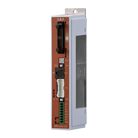
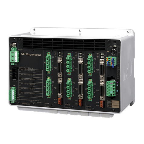
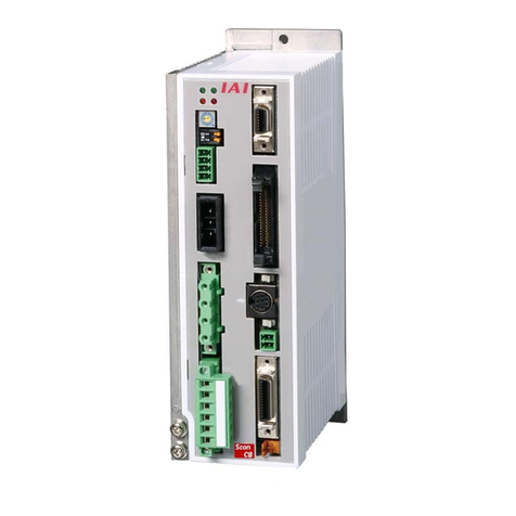
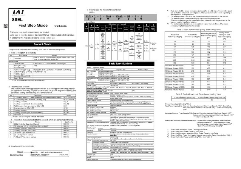
IAI SCON series User manual

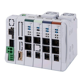
SCON
First Step Guide Seventh Edition
Thank you for purchasing our product.
Make sure to read the Safety Guide and detailed Instruction Manual (DVD) included with the product in addition to
this First Step Guide to ensure correct use.
This Instruction Manual is original.
•Using or copying all or part of this Instruction Manual without permission is prohibited.
•The company names, names of products and trademarks of each company shown in the sentences are registered
trademarks.
Product Check
This product is comprised of the following parts if it is of standard configuration.
If you find any fault in the contained model or any missing parts, contact us or our distributor.
1. Parts
No. Part Name Model Reference
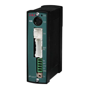
1 Controller Main Body
Refer to “How to read the model plate”, “How to read the model”
Accessories
2 I/O Flat Cable CB-PAC-PIO*** *** shows the cable
length
3 Service Connector for Pulse
Train Control Plug : 10114-3000PE, Shell : 10314-52F0 (Supplier : 3M) Enclosed in SCON-C/CA
4 System I/O Plug FMC1.5/4-ST-3.5 (Supplier : Phoenix Contact)
5 Power Supply Plug for Brake MC1.5/2-ST-3.5 (Supplier : Phoenix Contact)
Applicable Cable Size
0.5mm2(AWG20)
6 AC Power Supply plug MSTB2.5/6-STF-5.08 (Supplier : Phoenix Contact) Applicable Cable Size
2.0mm2(AWG14)
7 Absolute Battery AB-5 Enclosed in Absolute Type
8 Dummy plug DP-5 Enclosed in SCON-CGAL
9 First Step Guide
10 Instruction Manual (DVD)
11 Safety Guide
2. Teaching Tool (to be purchased separately)
A teaching tool such as PC software is necessary when performing the setup for position setting, parameter
setting, etc. that can only be done on the teaching tool.
Please prepare either of the following teaching tools such as PC software.
No. Part Name Model
1 PC Software
(RCS232C converter adapter and external equipment communication cable are included) RCM-101-MW
2 PC Software
(USB converter adapter, USB cable and external equipment communication cable are included)
RCM-101-USB
3 Touch Panel Teaching CON-PTA CON-PTA
4 Touch Panel Teaching CON-PDA (Dead-man switch is included) CON-PDA
5 Touch Panel Teaching CON-PGAS (Dead-man switch and TP adapter are included) CON-PGAS
6 Touch Panel Teaching TB-01 TB-01
7 Touch Panel Teaching TB-01 (with dead-man switch attached on the left) TB-01D
8 Touch Panel Teaching TB-01 (with dead-man switch attached on the right) TB-01DR
3. Instruction manuals related to this product, which are contained in the Instruction manual (DVD).
No. Name Manual No.
1 SCON Controller Instruction Manual ME0161
2 SCON-CA/CAL/CGAL Controller Instruction Manual ME0243
3 PC Software RCM-101-MW/ RCM-101-USB Instruction Manual ME0155
4 Touch Panel Teaching CON-PTA/PDA/PGAS Instruction Manual ME0295
5 Touch Panel Teaching TB-01 Position Controller Instruction Manual ME0324
4. How to read the model plate
5. How to read controller model
Basic Specifications
List of Specifications
SCON-C/CA
Item
Less than 400W 400W or more
SCON-CAL/CGAL
Corresponding Motor Capacity 12W to 399W 400W to 750W 12W to 200W
Power-supply Voltage
Single-Phase 100 to 115V AC
(Power fluctuation within
±
10%)
Single-Phase 200 to 230V AC
(Power fluctuation within
±
10%)
Single-Phase 200 to 230V AC
(Power fluctuation within
±
10%)
Single-Phase 100 to 115V AC
(Power fluctuation within
±
10%)
Single-Phase 200 to 230V AC
(Power fluctuation within
±
10%)
Power-supply Voltage 100V AC
Rush
Current*1
Power-supply Voltage 200V AC
20A (Controller side), 70A
(Drive side) 20A (Controller side),
80A (Drive side)
30A (Controller side),
80A (Drive side)
Load Capacity Refer to Power Capacity and Heat Generation
Leak Current*2 3.0mA Primary side when noise filter is connected to power supply line
Heat Generation Refer to Power Capacity and Heat Generation
Power Supply Frequency 50/60Hz
PIO Power Supply*3 24V DC±10%
Power Supply for Electromagnetic Brake
(for actuator equipped with brake)
24V DC±10% 1A (MAX.)
(supplied from external equipment)
SCON-C : 10ms (50Hz), 8ms (60Hz)Transient Power Cutoff Durability
SCON-CA : 20ms (50Hz), 16ms (60Hz)
20ms (50Hz), 16ms (60Hz)
Motor Control System Sine Wave PWM Vector Current Control
Corresponding Encoder Incremental Serial Encoder, Absolute Serial Encoder,
ABZ (UVW) Parallel Encoder
Incremental Serial Encoder,
Absolute Serial Encoder,
Actuator Cable Length MAX. 20m
Serial Communication Interface RS485 : 1CH … based on Modbus Protocol RTU/ASCII
Speed : 9.6 to 230.4Kbps
Control available with serial communication in the modes other than the pulse train
PIO
Specifications
Signal I/O dedicated for 24V DC (selected from NPN/PNP) … Input 16 ports max.,
output 16 ports max.
External Interface
(Each dedicated
controller) Fieldbus
Specification
DeviceNet/CC-Link/PROFIBUS/CompoNet*/MECHATR
OLINK*/EtherCAT*/EtherNET/IP*/PROFINET IO*
(*Specified only for SCON-CA)
DeviceNet/CC-Link/PROFIB
US/CompoNet/MECHATRO
LINK/EtherCAT/EtherNET/I
P/PROFINET IO
PIO MAX. 10m
RS485 Total cable length 100m or less.
Cable Length
Fieldbus Refer to each Fieldbus specification
Data Setting and Input PC Software, Touch Panel Teaching, Teaching Pendant
SCON-C : Saves position data and parameters to
non-volatile memory
(Limitation in number of writing 100,000 times)
Data Retention Memory
SCON-CA : Saves position data and parameters to
non-volatile memory
(There is no limitation in number of writing)
Saves position data and
parameters to non-volatile
memory
(There is no limitation in
number of writing)
Operation Mode Positioner Mode/Pulse Train Control Mode
(selected by Pulse Train Mode Changeover Switch on
Front Panel)
Positioner Mode
Number of Positions in Positioner
Mode
Standard 64 points, maximum 512 points (PIO Type), 768 points (only for SCON-CA Fieldbus Type)
(Note) Number of positions differs depending on the selection in PIO pattern and fieldbus operation mode.
SCON-C : Differential System (Line Driver System) :
MAX. 500Kpps
SCON-CA : Differential System (Line Driver System) :
MAX. 2.5Mpps
Input Pulse Frequency
Common to C/CA
: Open Collector Type :
200Kpps max. (under condition AK-04 is used)
Pulse Train
Control
Mode
(Dedicated
for PIO
Specifications)
Command Pulse
Multiplying Factor
(Electrical Gear : A/B)
1/50 < A/B <50/1
Setting Range of A and B (set to parameter) : 1 to 4096
SCON-C :
Differential System (Line Driver
System
):
MAX. 500Kpps (Linear output available up to
109Kpps)
SCON-
CA
:
Differential System (Line Driver System):
MAX. 2.5Mpps
Feedback Pulse
(Dedicated for PIO Specifications)
Common to C/CA
:
Open
Collector Type
:
MAX. 500Kpps (under condition JM-08 is used)
LED Display
(mounted on Front Panel)
PWR (green) : Controller in normal condition,
SV (green) : Servo on,
ALM (orange) : Alarm generated,
EMG (red) : Emergency Stop
PWR (green) : Controller in
normal condition / SV
(green) : Servo on / ALM
(orange) : Alarm generated /
EMG (red) : Emergency
Stop / WRG (orange) :
Warning generated
Electromagnetic Brake Compulsory Release
Switch (mounted on Front Panel)
Switching NOM (standard)/BK RLS (compulsory release)
Insulation Resistance 500V DC 10MΩor more
Insulation Strength 1,500V AC for 1 min. (Note) Withstand voltage of force control loadcell is 50V DC
Surrounding air temperature
0 to 40°C
Surrounding humidity
85%RH or less (non-condensing)
Surrounding environment
[Refer to Installation Environment]
Surrounding storage temperature
-20 to 70°C (non-condensing)
Surrounding storage humidity
85% or less (non-condensing)
Environment
Vibration Durability
XYZ Each direction 10 to 57Hz Pulsating amplitude 0.035mm (continuous) 0.075mm (intermittent)
57 to 150Hz 4.9m/s
2
(continuous) 9.8m/s
2
(intermittent)
Protection Class IP20 or equivalent
Weight SCON-C : Approx. 800g
SCON-CA : Approx. 900g
SCON-C : Approx. 1100g
SCON-CA : Approx. 1200g
Approx. 560g
Cooling Method Natural air-cooling Forced Air Cooling Forced Air Cooling
External Dimensions 58W ×194H ×121D [mm] 72W ×194H ×121D [mm] 49W ×158H ×116D [mm]
*1 In-rush current will flow for approximately 20msec after the power is turned on (at 40°C).
Note that the value of in-rush current differs depending on the impedance of the power supply line.
*2
Leak current varies depending on the capacity of connected motor, cable length and the surrounding environment. Measure the
leak current at the point where a ground fault circuit interrupter is to be installed when leakage protection is conducted.
A ground fault circuit interrupter needs to be selected carefully considering the purposes of prevention of fire and
protection of human.
Use the harmonic type (for inverter) for the ground fault circuit interrupter.
*3 It is not necessary to supply power to PIO when operating with using ROBONET, Gateway Unit or SIO Converter
without using PIO. In this case, set the parameter No. 74 (PIO Power Supply Monitor) to “1” (Invalid). It will generate
the error code No. 0CF (I/O 24V Power Supply Error) if the setting is not done.
Power Capacity and Heat Generation
Rated Power Capacity =Motor Power Capacity +Control Power Capacity
Peek Max. Power Capacity =Peek Max. Motor Power Capacity +Control Power Capacity
Actuator Motor Type
Motor Power
Capacity
[VA]
Peek Max. Motor
Power Capacity
[VA]
Control Power
Capacity
[VA]
Rated Power
Capacity
[VA]
Peek Max. Power
Capacity [VA]
Heat Generation
[W]
12 41 123 89 171 30
30D (Excluding RS) 46 138 94 186 31
30R (for RS) 138 414 186 462 33
60 138 414 186 462 33
60 (RCS3-CTZ5) 197 591 245 639 32
100 234 702 282 750 35
100S (LSA) 283 851 331 899 36
150 328 984 376 1032 37
200 421 1263 469 1311 38
200S
(LSA excluding LS A-N15H)
486 1458 534 1506 38
200S (LSA-N15H) 773 2319 821 2367 56
300S (LSA) 662 1986 710 2034 40
400 920 2760 968 2808 45
400 (RCS3-CT8) 1230 3690 1278 3738 47
600 1164 2328 1212 2376 56
750 3042 3090
750S 1521 4563
48
1569 4611 58
RS : Rotary Shaft LSA : Linear Actuator
Selection of Circuit Interrupter
• 3 times of the rated current flows to the controller during the acceleration/deceleration. Select an interrupter that does not trip
with this value of current. If a trip occurs, select an interrupter that possesses the rated current of one grade higher. (Refer to
the operation characteristics curves in the product catalog.)
• Select an interrupter that does not trip with the in-rush current. (Refer to the operation characteristics curves in the product
catalog.)
• Consider the current that enables to cutoff the current even when a short circuit current is flown for the rated cutoff current.
Rated Interrupting Current >Short Circuit Current =Primary Power Capacity / Power Voltage
Consider margin for the rated current on the circuit breaker.
Rated Current for Circuit Interrupter >(Rated Motor Power Capacity [VA] +Control Power Capacity [VA]) /
AC Input Voltage ×Safety Margin (reference 1.2 to 1.4 times)
External Dimensions
SCON-C/CA
Less than 400W 400W or more
SCON-CAL/CGAL
DIN Rail
(8.5)
35.4 (Width of 35mm DIN Rail )
* There is no DIN rail part on the type with screw attachment. For DIN Rail
Mounting Type
82.5 from DIN rail center
130.7
116
4
49
158
(17)
For Screw-fixed Type
(6)
4.5
φ4.5
22.5
(6)
146.5
Serial numbe
r
Model
SCON-CA-60A-NP-2-1
MODEL
SERIAL No.
800056144 L11
MADE IN JAPAN
SCON-CA-20 I HA-NP-3-1-DN-**
<Series>
<Type>
C : Standard Type CA : High Performance Type
CAL : Small Type CGAL : Small Global Type
<Actuator Characteristics>
[Motor Type] * For SCON- CAL/CGAL, 200W or Less
12 : 12W 200 : 200W
20 : 20W 200S : 200W (LSA)
30D : 30W (Excluding RS) 300S : 300W (LSA)
30R : 30W (for RS) 400 : 400W
60 : 60W 600 : 600W
100 : 100W 750 : 750W
100 S : 10 0W (LSA) 75 0S : Equipped with Loadcell
150 : 150W RCS2-RA13R
<Encoder Type>
I : Incremental
A : Absolute
G : Spurious Absolute(Note 3)
<Option>
No Indication : Standard Type HA : High Acceleration/Deceleration Type
I : Index Absolute Type (DD)
(Note 3)
M : Mul ti-Rotation Absolute Type (DD)
(Note 3)
<Identification for IAI use only>
* There is no identification in some cases.
< Type of Installation
(dedicated for SCON-CAL/CGAL) >
Not Specified : Screw Attachment Type
DN : DIN Rail Mounting Type
<Power-supply Voltage>
1 : Single-Phase 100V AC
2 : Single-Phase 200V AC
<I/O Cable Length>
0 : Equipped with no cable
2 : 2m
3 : 3m (Standard)
5 : 5m
121min80
58
29
φ4.2
184
194
(200.5)
5
4.2
Absolute Battery
(for Absolute Encoder Type)
72
43
φ4.2
4.2
5
184
194
(200.5)
Absolute Battery
(for Absolute Encoder Type)
Side View (in common)
Warning : Operation of this equipment requires detailed installation and operation instructions which are
provided on the DVD Manual included in the box this device was packaged in. It should be retained
with this device at all times.
A hardcopy of the Manual can be requested by contacting your nearest IAI Sales Office listed at
the back cove
r
of the Instruction Manual or on the First Ste
p
Guide.
<I/O Type>
NP : NPN Specification (Sink Type) (Standard) ML : MECHATROLINK Connection 1,2 Type
(Note 2)
PN : PNP Specification (Source Type) ML3 : MECHATROLINK Connection 3 (Motion) Type
(Note 1)
DV : DeviceNet Connection Type EC : EtherCAT Connection Type
(Note 2)
CC : CC-Link Connection Type EP : EtherNet/IP Connection Type
(Note 2)
PR : PROFIBUS Connection Type PRT : PROFINET-IO Connection Type
(Note 2)
CN : CompoNet Connection Type
(Note 2)
(Note 1) Specified only for SCON-CA (Note 2) Except for SCON-C (Note 3) Specified only for SCON-C/CA

CB-RCS2-PLLA
RCS2-RA13R
(with Loadcel)
Absolute Battery
(for Absolute Type)
24V DC
Power Supply for Brake
Absolute Battery
(for Absolute Type)
Actuator
The following models are excluded:
•RCS2-RA13R with brake or loadcell equipped
•NS Actuators with brake equipped
24V DC
Power Supply for Brake
For LS (option)
Brake Box
CB-RCS2-PLA010
(enclosed to Brake Box)
For LS (option)
• NS Actuators (with Brake㧕
•RCS2-RA13R (with Brake㧕
Connect to back side
Absolute Battery
(for Absolute Type)
16.85 17.15
1.5
φ5
4.5
145
154
136
R2.5
4.5
106.5
5
30.7
34
1.5
1.5
Ø5
4.5
145
154
136
4.5
115
5
30.7
34
1.5
4
4
8.5
(77 from DIN rail center)
(9)
Regenerative Resistor Unit (Option) : RESU(D)-1, RESU(D)-2
This is a unit that converts the regenerative current to heat when the motor decelerates.
[Specification] [Appearance]
Item Specification
Body Size W35.6mm ×H158mm ×D115mm
Body Weight 0.7kg
Internal Regenerative Resistor 235Ω80W
2nd unit
or later
RESU-1
RESUD-1
Controller Connection Cable
(Model Code CB-ST-REU010) 1m
Acces
sories
First Unit RESU-2
RESUD-2
Controller Connection Cable
(Model Code CB-SC-REU010) 1m
[Reference Connectable Quantity]
Motor Wattage
Horizontal Mount/Vertical Mount
Connectable Number of
Regenerative Resistor Units
To 1 0 0 W (Note 3) Not Required
101 to 400W 1
401 to 750W 2
(Note 1) This is a reference for the case when the actuator is ran
forward and backward on 1,000mm stroke with the operation duty 50%
under the rated acceleration/deceleration speed and rated load.
(Note 2) It is necessary to have the regenerative resistor listed above when the
operation duty is above 50%.
The maximum quantity of the external regenerative resistor units that
can be connected is as stated below:
•2 units for less than 400W •4 units for 400W or more
(Note 3) It is necessary to have one unit for LSA/LSAS-N10S Type.
Brake Box (Option) : RCB-110-RA13-0
This is applied on NS Actuator and RCS-RA13R with brake.
1 unit of Brake Box possesses brakes for 2 shafts.
[Specification] [Appearance]
Item Specification
Body Size W162 ×H94 ×D65.5mm
Power Voltage and Current 24V DC±10% 1A
Connection Cable Encoder Cable
(Model Code CB-RCS2-PLA010) 1m
[24V Power Supply Connector]
Connector on
Cable Side
(Enclosed in
standard package)
MC1.5/2-STF-3.5 (Phoenix Contact)
Applicable Cable AWG28 to 16
Pin No. Signal Explanation
1 0V Power Supply Grounding for
Brake Excitation
Terminal
Assignment 2 24VIN For Brake Excitation and
24V Power Supply
[Connectors 1 and 2 for external brake release switch connection]
Connected
Equipment Brake Release Switch
Connector on
Cable Side
(Please prepare
separately)
XAP-02V-1
(Contact BXA-001T-P0.6) (JST)
Switch Rating 30V DC Minimum Current 1.5mA
Pin No. Signal Explanation
1 BKMRL Brake Release Switch Input
Terminal
Assignment 2 COM
Power Supply Output for Brake
Release Switch Input
(Note) Short circuit of pin No. 1 and 2 of this connector releases the brake compulsorily.
Same as the brake release switch on SCON main unit, it is possible to release the brake.
Do not keep the compulsory release condition while in automatic operation.
Loadcell (Dedicated Option for SCON-CA)
This is the pressing force measurement unit that is used for the force control.
This is used by connecting to the actuator corresponding to the force control.
[Specification]
Item Specification
Loadcell System Strain Gauge
Rated Capacity 20000N
Allowable Overload 200%R.C*1
Loadcell Accuracy ±1%R.C*1
Zero ±0.2%R.C/10°C
Temperature Drift Output ±0.1%R.C/10°C
Applicable Temperature Range
0 to 40°C
*1 R.C.: Rated Capacity
[Refer to RCS2-RA13R Instruction Manual for details of how to attach and the dimensions.]
Installation Environment, Storage Environment
This product is capable for use in the environment of pollution degree 2*1 or equivalent.
*1 Pollution Degree 2: Environment that may cause non-conductive pollution or transient conductive
pollution by frost (IEC60664-1)
1. Installation Environment
Do not use this product in the following environment
•Location where the surrounding air temperature exceeds the range of 0 to 40°C
•Location where condensation occurs due to abrupt temperature changes
•Location where relative humidity exceeds 85%RH
•Location exposed to corrosive gases or combustible gases
•Location exposed to significant amount of dust, salt or iron powder
•Location subject to direct vibration or impact
•Location exposed to direct sunlight
•Location where the product may come in contact with water, oil or chemical droplets
•Environment that blocks the air vent [Refer to Installation and Noise Elimination]
When using the product in any of the locations specified below, provide a sufficient shield.
•Location subject to electrostatic noise
•Location where high electrical or magnetic field is present
•Location with the mains or power lines passing nearby
2. Storage and Preservation Environment
The storage and preservation environment should comply with the same standards as those for the
installation environment. In particular, when the machine is to be stored for a long time, pay close
attention to environmental conditions so that no condensation forms. Unless specially specified,
moisture absorbency protection is not included in the package when the machine is delivered. In
the case that the machine is to be stored and preserved in an environment where condensation is
anticipated, take the condensation preventive measures from outside of the entire package, or
directly after opening the package.
Installation and Noise Elimination
1. Noise Elimination Grounding (Frame Ground)
2. Precautions regarding wiring method
1) Wire is to be twisted for the 24V DC power supply.
2) Separate the signal and encoder lines from the power
supply and power lines.
3. Noise Sources and Elimination
Carry out noise elimination measures for power devices on
the same power path and in the same equipment.
The following are examples of measures to eliminate noise
sources.
1) AC solenoid valves, magnet switches and relays
[Measure] Install a Surge absorber parallel with the coil.
2) DC solenoid valves, magnet switches and relays
[Measure] Mount the windings and diodes in parallel.
Select a diode built-in type for the DC relay
4. Heat Radiation and Installation
Design and Build the system considering the size of the controller box, location of the controller and
cooling factors to keep the ambient temperature around the controller below 40°C. Apply screws sized
M4 × 10mm when attaching the product with screws.
SCON-C/CA
SCON-CAL/CGAL
Connection Diagram
SCON-C/CA
●Standard
●For Models Equipped with brake Except for RCS2-RA13R and NS Actuators
●RSC2-RA13R Equipped with Brake, with no Loadcell, or NS Actuators with Brake
●RCS2-RA13R Equipped with no Brake, with Loadcell in SCON-CA
●RCS2-RA13R Equipped with Brake and Loadcell in SCON-CA
A
ttached to RCS2-RA13R
Loadcell
94
70
12
55 152
162
142
4-φ5
LS Input Connector
Encoder Input Connector
Encoder Output Connector
Primary
Shaft
min100
12
Connector 2 for
External Brake Release
Switch Connection
(for the primary shaft)
Power Supply
Input Connector
POWER ON LED
(turns in green while on)
Connector 2 for
External Brake Release
Switch Connection
(for the secondary shaft)
Secondary
Shaft
CB-LDC-LTL
CB-RCS2-PLLA
RCS2-RA13R
(with Loadcell and Brake)
CB-RCS2-PLA (enclosed to Brake Box)
24V DC
Brake Box
RCB-110-RA13-0
Connect to back side
Absolute Battery
(for Absolute Type)
Power Supply for Brake
10mm or more
50mm
or more
50mm
or more
50mm
or more
50mm
or more
50mm
or more
50mm
or more
100mm
or more
30mm
or more
10mm
or more
100mm
or more
150mm
or more
Air Flow
Air Flow
Fan
Brake Box
Regenerative
Resistor Unit
Place a fan to make the
ambient temperature even
Earth Terminal
Connect using FG connection
terminal on the main unit.
Copper Wire :
Connect to an ground cable with
diameter 1.6mm or more.
Controller
Class D grounding
(Formerly Class-III grounding :
Grounding resistance at 100
Ω
or less)
Do not share the ground wire with or connect
to other equipment. Ground each controller.
Controller
Other
equipment
Controller
Other
equipment
Other
equipment
Surge absorber
Relay
coil
Relay coil
R
C
+24V 0V
+24V 0V
+-
Screw
Attachment
Type
RESU-1
RESU-2
DIN rail
Attachment
Type
RESUD-1
RESUD-2
Regenerative Resistor Unit
(REU-2 : option)
Required depending
on usage condition
LED Indication
Axis Number
Setting Switch
Pulse Train Mode
Changeover Switch
System
I/O Connector
CB-SC-REU010
CB-ST-REU010
Regenerative Resistor Unit
(REU-1 [for secondary unit] : option)
Power Supply
Connector
FG Connection
Terminal
Absolute Battery
(for Absolute Type)
Mode Changeover Switch
Brake Release Switch
Brake Power Supply Connector
AK-04 (option)
Converts PLC open
collector output into
differential pulse output
JM-08 (option)
Converts SCON differential
pulse output into open
collector output
Flat Cable
(Accessories)
PLC
(Please prepare separately)
Touch panel teaching (option)
or Teaching pendant (option)
PC Software (option)
Detail View of Pulse Train Mode Changeover Switch
Pulse Train Mode Changeover Switch No. 1
ON: to select Pulse Train Control Mode
OFF: to select Positioner Mode
Actuator
The following models are excluded:
·RCS2-RA13R with brake or loadcell equipped
·NS Actuators with brake equipped
AK-04
JM-08
Wiring
f
or Pulse
Train Control Mode
SW
ADRS
1 2
ON
↓

SCON-CAL/CGAL
EMG Switch
Regenerative Resistor Unit
Required in some conditions of use.
Noise Filter
Required for noise
prevention.
Host
Control
System
Circuit Breaker
Select a circuit breaker
applicable for the capacity
of the controller.
Actuator
PC Software
<RCA 101-MW>
Optional
PC
24V DC
NFB Grounding
Absolute
Battery
Brake Power
Supply
Teaching Pendant
(Option)
LED Display
Changeover
Switch
Brake Release Switch
(Note) Axis address setting is to be conducted in parameters.
●Connected of Actuator
Power Supply and Emergency Stop Circuit
●Wiring for Power Supply (to be prepared by customer)
Power consumption of SCON varies depending on the connected actuator, etc. Select the circuit breaker that suits to the
specification.
[Refer to Basic Specifications]
A ground fault circuit interrupter needs to be selected carefully considering the purposes of prevention of fire and protection
of human.
Have a measurement of the leak current where a ground fault circuit interrupter is to be installed.
Use the “harmonic type” for the ground fault circuit interrupter.
*1 CLF : Clamp Filter … It is recommended to attach it to improve noise immunity.
*2 SK : Surge Killer … It is recommended to attach it to improve noise immunity.
*3 NF : Noise Filter … Make sure to install it. It is recommended to have it installed within 0.3m of the cable length from
SCON.
Parts Name Supplier Model
CLF Clamp Filter TDK ZCAT3035-1330
SK Surge Protector
OKATANI ELECTRIC CO.,LTD
R.A.V-781BWZ-2A
SOSHIN ELECTRIC CO.,LTD NF2010A-UP
COSEL NAC-10-472
NF Noise Filter
DENSEI-LAMBDA MC1210
●Wiring for Emergency Stop Input
The following diagram shows an example of how the emergency stop switch for the teaching pendant may be
included in the emergency stop circuit you may construct.
Note 1 When the teaching pendant is not connected, S1 and S2 become short-circuited inside the controller.
Note 2 Connect a contactor to L1 and L2 terminals for external power cutoff by the emergency stop if the motor power is
required to be cut off externally to comply with the Safety Categories.
Note 3 The rating for the emergency stop signal to turn ON/OFF at contact CR1 is 24V DC and 10mA.
Note 4 For CR1, select the one with coil current 0.1A or less.
I/O Signal
Explanation of I/O Signal Functions
Category
Abbreviated
Code Signal Name Contents of Functions
CSTR Start Signal (PTP Strobe) Starts moving toward the position set in Command Position No.
PC1 to PC256 Command Position No. To input position No. desired to move (binary input)
BKRL Brake Compulsory
Release To release the brake compulsorily
RMOD Operation Mode
Changeover
Operation Mode can be changed over when MODE Switch on the controller
is on AUTO. The setting is AUTO when signal is OFF, and MANU when ON.
*STP Pause Turn the signal off during operation to decelerate and stop. Turn the signal
ON to resume the operation.
RES Reset Turn the signal on to reset the alarm. Also, it is possible to cancel the
residual operation if turning on during the pause (*STP is off).
SON Servo ON Turn on to turn the servo ON, and off to turn the servo OFF.
HOME Home return Perform the home-return operation with the signal rising edge (OFF →
ON).
MODE Teaching Mode
Turn the signal on to set to the Teaching Mode, and off to cancel the
Teaching Mode. The mode will not be switched over unless CSTR, JOG+
and JOG−are all off and the actuator operation is stopped.
JISL Jog/Inching Changeover
Jog Operation can be performed with JOG+and JOG−while this signal is
off.
Inching Operation is performed with JOG+and JOG−when it is on.
JOG+
JOG−Jog
Jog Operation is performed to positive direction by detecting ON edge of
JOG+signal and to negative direction by JOG−signal while JISL signal is
off. The actuator will decelerate and stop if OFF edge is detected while in
each Jog Operation.
Inching Operation is performed while JISL signal is on.
PWRT Teaching
Write the current position to the indicated position if indicating the written
position and turn this signal on for more than 20ms during the Teaching
Mode.
CLBR
(Specified only
for CA)
Loadcell Calibration
Command Turn this signal on for more than 20ms to perform calibration of loadcell.
ST0 to ST6 Start Signal 0 to 6
The actuator moves to the commanded position with this signal on during
the electromagnetic valve mode.
(CSTR signal is not required)
TL Torque Limit Select Puts torque limitation to the motor with the signal on and the value set to
the parameter.
DCRL Deviation Counter Clear Clears the deviation count with the signal on.
Input
CSTP Compulsory Stop Performs compulsory stop of the actuator. Turn the signal on to decelerate
and stop the actuator and turns the servo off.
PEND/INP Position Completion
Turns on in the positioning band range after actuator operation. PEND
signal will not turn off once it turns on until the next operation even if the
actuator goes off the range of positioning band. INP will turn off. PEND
and INP can be switched over by the parameter.
PM1 to PM256 Completion Position No. Outputs (binary output) the position No. that is reached at the same time
the positioning is complete.
HEND Home Return Completion Turns on when home-return operation is complete. It will be kept on unless
the home position is lost.
ZONE1, 2 Zone Turns on if the current actuator position is within the range set to the
parameter.
PZONE Position Zone
Turns on when the current actuator position gets into the range set to the
position data during the move towards the position. It can be utilized
together with ZONE 1, however, PZONE is effective only when moving
towards the set position.
RMDS Operation Mode Output Outputs the operation mode status. It turns on when the controller is on
Manual Mode.
*ALM Alarm Turns on when controller in normal condition, and off when alarm is
generated.
MOVE While in Operation Turns on during the actuator is moving (including home-return operation
and pressing operation).
SV Servo ON status
Turns on when the servo is on.
*EMGS Emergency Stop Output Turns on when the controller emergency stop is cancelled, and off during
the emergency stop (regardless of alarms).
MODES Teaching Mode Output Turns on when it turns to the Teaching Mode by MODE signal input. It is off
in the normal mode.
WEND Writing Complete Turns on after the writing by PWRT signal is complete in the Teaching
Mode. This signal turns off if PWRT signal is turned off.
PE0 to PE6 Current Position Number Turns on when moving to the target position is complete in
Electromagnetic Valve Mode.
LS0 to LS2 Limit Switch Output
Turns on when the current actuator position is within the range of
positioning band (±) of the target position. It is output even before the
movement command and the servo is off if the home-return operation is
completed.
CEND
(Specified only
for CA)
Loadcell Calibration
Complete
Turns on after loadcell calibration is complete. This signal turns off if CLBR
signal is turned off.
*BALM Warning for Absolute
Battery Voltage Drop
Turns on when the battery voltage for the absolute type actuator is within
the normal voltage range. Replace the battery if it is turned off. (this signal
is always on for the incremental type actuator.)
LOAD
(Specified only
for CA)
Load Output Judgment
Signal
Outputs when current exceeds the value set to “threshold” within range of
position data “ZONE+” or “ZONE−” during the pressing operation.
Utilize this signal for a judgment of a press-fitting process being properly
performed, etc.
TRQS Torque Level Output
Outputs when current of motor reaches the value set to “threshold” by the
slider (or rod) being hit to an obstacle during the pressing movement (and
before home-return operation in PIO Pattern 5).
ALM1 to 8 Alarm Code Output Outputs the alarm code when an alarm is generated
TLR Torque Limit Restricted
Turns on when torque reaches the limit while in torque restriction (TL
signal is on).
PWR System Standby Turns on when the controller is able to be controlled.
Output
*ALML Light Error Alarm
(only for SCON-CA)
This turns on when any of the absolute battery alarm, overload alarm or
message level alarm is occurred.
100V AC
or
200V AC
(Refer to Controller
Power Voltage Specifications)
Circuit
Breaker
Ground Fault
Circuit
Interrupter
*3
NF
*2
SK
CLF
Class D grounding
(Formerly Class-III grounding)
+24V
0V
24V DC
Power
Supply
SCON
AC Power Supply
Input Connector
B. Motor Power Unit
A. Control power supply
L1
L2
L1C
L2C
NC
PE
BK+
PWR-
Brake Power Supply
Input Connector
PIO
Connector
Brake
Release Box
*1
24V
Emergency stop
reset switch
Emergency stop
switch
Emergency stop switch
for the teaching pendant
(Note 1)
SCON
First unit
SCON
Second
unit
SCON
Nth unit
S1 S2 S1 S2 S1 S2 CR1
(Note 1)
0V
MC1
CR1
CR1
CR1
(Note 1)
MC1
(Note 2)
AC100V
AC200V
SCON-C/CA/CAL
SCON-CGAL
EMG+
EMG-
L1
L2
L1C
L2C
24V
Motor power cutoff relay
Motor
power supply
Control
power supply
CR1
(Note 1)
MC1
(Note 2)
AC100V
AC200V
EMG+
EMG-
L1
L2
L1C
L2C
SCON-C/CA/CAL
Second unit
EMG-
EMG+
CR1
(Note 1)
24V
MC1
(Note 2)
AC100V
AC200V L1
L2
L1C
L2C
Motor
power supply
Control
power supply

Signal Assignment for Each Mode
The signal assignment of I/O flat cable by the PIO pattern is as shown below. Follow the following table to connect the external equipment (such as PLC).
Corresponding Type All Types
Selection in Parameter No. 25 (PIO Pattern)
0 1 2 3
Category
PIO Functions
Positioning mode Teaching mode 256-point mode 512-point mode
Number of Positioning Points 64 points 64 points 256 points 512 points
Jog Signal ×{××
Teaching Signal (Current Position Writing)
×{××
Input
Brake Release {×{{
Signal during Operation {{××
Zone Signal {×××
Pin No.
Output
Position Zone Signal {{{×
1A 24V P24
2A 24V P24
3A −−
4A −−
5A IN0 PC1 PC1 PC1 PC1
6A IN1 PC2 PC2 PC2 PC2
7A IN2 PC4 PC4 PC4 PC4
8A IN3 PC8 PC8 PC8 PC8
9A IN4 PC16 PC16 PC16 PC16
10A IN5 PC32 PC32 PC32 PC32
11A IN 6 − MODE PC64 PC64
12A IN7 − JISL PC128 P128
13A IN8 − JOG+ − PC256
14A IN9 BKRL JOG− BKRL BKRL
15A IN10 RMOD RMOD RMOD RMOD
16A IN11 HOME HOME HOME HOME
17A IN12 *STP *STP *STP *STP
18A IN13 CSTR CSTR/PWRT CSTR CSTR
19A IN14 RES RES RES RES
20A
Input
IN15 SON SON SON SON
1B OUT0 PM1 (ALM1) PM1 (ALM1) PM1 (ALM1) PM1 (ALM1)
2B OUT1 PM2 (ALM2) PM2 (ALM2) PM2 (ALM2) PM2 (ALM2)
3B OUT2 PM4 (ALM4) PM4 (ALM4) PM4 (ALM4) PM4 (ALM4)
4B OUT3 PM8 (ALM8) PM8 (ALM8) PM8 (ALM8) PM8 (ALM8)
5B OUT4 PM16 PM16 PM16 PM16
6B OUT5 PM32 PM32 PM32 PM32
7B OUT6 MOVE MOVE PM64 PM64
8B OUT7 ZONE1 MODES PM128 PM128
9B OUT8 PZONE/ZONE2 PZONE/ZONE1 PZONE/ZONE1 PM256
10B OUT9 RMDS RMDS RMDS RMDS
11B OUT10 HEND HEND HEND HEND
12B OUT11 PEND PEND/WEND PEND PEND
13B OUT12 SV SV SV SV
14B OUT13 *EMGS *EMGS *EMGS *EMGS
15B OUT14 *ALM *ALM *ALM *ALM
16B
Output
OUT15 *BALM
*BALM *BALM *BALM
17B −−
18B −−
19B 0V N
20B 0V N
(Note) “*” in codes above shows the signal of the active low (A signal of active low is a signal that the input signal is processed when it is
turned OFF, output signal is ordinary on while the power is ON, and turns OFF when the signal is output.).
PM1 to PM8 indicate the alarm binary code output signal when an alarm is generated. [Refer to the instruction manual for details]
Corresponding Type All Types CA Type C/CA Types
Selection in Parameter No. 25 (PIO Pattern)
4 5 6 7
Category
PIO Functions
Electromagnetic
Valve Mode 1
Electromagnetic
Valve Mode 2
Force Control
Mode 1
Force Control
Mode 2
Pulse Train
Control Mode
Number of Positioning Points 7 points 3 points 32 points 5 points −
Jog Signal ×××××
Teaching Signal (Current Position Writing)
×××××
Input
Brake Release {{{{{
Signal during Operation ×××××
Zone Signal {{××{
Pin No.
Output
Position Zone Signal {{{{×
1A 24V P24
2A 24V P24
3A −−
4A −−
5A IN0 ST0 ST0 PC1 ST0 SON
6A IN1 ST1 ST1 [JOG+] PC2 ST1 RES
7A IN2 ST2 ST2*1 PC4 ST2 HOME
8A IN3 ST3 −PC8 ST3 TL
9A IN4 ST4 −PC16 ST4 CSTP
10A IN5 ST5 −−−DCLR
11A IN6 ST6 −−−BKRL
12A IN7 −−−−RMOD
13A IN8 −−CLBR CLBR −
14A IN9 BKRL BKRL BKRL BKRL −
15A IN10 RMOD RMOD RMOD RMOD −
16A IN11 HOME −HOME HOME −
17A IN12 *STP −*STP *STP −
18A IN13 −−CSTR −−
19A IN14 RES RES RES RES −
20A
Input
IN15 SON SON SON SON −
1B OUT0 PE0 LS0 PM1(ALM1) PE0 PWR
2B OUT1 PE1 LS1 [TRQS] PM2(ALM2) PE1 SV
3B OUT2 PE2 LS2*1 PM4(ALM4) PE2 INP
4B OUT3 PE3 −PM8(ALM8) PE3 HEND
5B OUT4 PE4 −PM16 PE4 TLR
6B OUT5 PE5 −TRQS TRQS *ALM
7B OUT6 PE6 −LOAD LOAD *EMGS
8B OUT7 ZONE1 ZONE1 CEND CEND RMDS
9B OUT8
PZONE/ZONE2 PZONE/ZONE2 PZONE/ZONE1 PZONE/ZONE1
ALM1
10B OUT9 RMDS RMDS RMDS RMDS ALM2
11B OUT10 HEND HEND HEND HEND ALM4
12B OUT11 PEND −PEND PEND ALM8
13B OUT12 SV SV SV SV −/*ALML*2
14B OUT13 *EMGS *EMGS *EMGS *EMGS −
15B OUT14 *ALM *ALM *ALM *ALM ZONE1
16B
Output
OUT15 *BALM *BALM *BALM *BALM ZONE2
17B −−
18B −−
19B 0V N
20B 0V N
(Note) Shown in [ ] after the signal names above tell the functions performed before the home-return operation. “*” in codes above
shows the signal of the active low.
PM1 to PM8 indicate the alarm binary code output signal when an alarm is generated. [Refer to the instruction manual for details]
PIO Input and Output Interface
Input section Output section
Input voltage 24V DC±10% Load voltage 24V DC
Input current 4mA 1 circuit : Peak load electric
current
SCON-C/CA :
100mA/1 point, 400mA/(Load current total)
SCON-CAL/CGAL :
50mA/1 point, 400mA/(Load current total)
Specifi-ca
tion
ON/OFF voltage ON voltage MIN. 18V DC
OFF voltage MAX. 6V DC Leak Current MAX.0.1mA/1 point
N
P
N
Controller
Internal
Power Supply
P24
Input Terminal
680Ω
5.6kΩ
External
Power Supply
24V DC
±10%
Controller
10Ω
N
Output Terminal External
Power Supply
24V DC
±10%
Internal
Power Supply
Load
P24
SCON-CA/CAL/CGAL
P
N
P
Controller
Internal
Power Supply
Input Terminal
680Ω
5.6kΩ
External
Power Supply
24V DC
±10%
N
Controller
P24
10Ω
N
External
Power Supply
24V DC
±10%
Internal
Power Supply
⽶⩄
⽶⩄
Load
Output Terminal
Output Terminal
Output Terminal
N
P
N
Controller
Internal
Power Supply
Input Terminal
External
Power Supply
24V DC
±10%
Logic Circuit
Controller
10Ω
N
Output Terminal External
Power Supply
24V DC
±10%
Internal
Power Supply
Load
P24
SCON-C
P
N
P
Controller
Internal
Power Supply
Input Terminal
External
Power Supply
24V DC
±10%
Logic Circuit
Controller
P24
10Ω
N
External
Power Supply
24V DC
±10%
Internal
Power Supply
⽶⩄
⽶⩄
Load
Output Terminal
Output Terminal
Output Terminal
NPN Specification PNP Specification
I/O Cable
Model :CB-PAC-PIO□□□
(Enter the cable length (L) in □□□ Example. 020 = 2m)
No. Signal Name Cable Color Wiring No. Signal Name Cable Color Wiring
1A 24V BR-1 1B OUT0 BR-3
2A 24V RD-1 2B OUT1 RD-3
3A −OR-1 3B OUT2 OR-3
4A −YW-1 4B OUT3 YW-3
5A IN0 GN-1 5B OUT4 GN-3
6A IN1 BL-1 6B OUT5 BL-3
7A IN2 PL-1 7B OUT6 PL-3
8A IN3 GY-1 8B OUT7 GY-3
9A IN4 WT-1 9B OUT8 WT-3
10A IN5 BK-1 10B OUT9 BK-3
11A I N6 B R-2 11B OU T 10 BR -4
12A IN7 RD-2 12B OUT11 RD-4
13A IN8 OR-2 13B OUT12 OR-4
14A IN9 YW-2 14B OUT13 YW-4
15A IN10 GN-2 15B OUT14 GN-4
16A IN11 BL-2 16B OUT15 BL-4
17A IN12 PL-2 17B −PL-4
18A IN13 GY-2 18B −GY-4
19A IN14 WT-2 19B 0V WT-4
20A IN15 BK-2
Flat Cable○
A
(Insulation-Displacement
Connectors)
AWG28
20B 0V BK-4
Flat Cable○
B
(Insulation-Displacement
Connectors)
AWG28
Operation in Pulse Train Control Mode (Only for SCON-C/CA)
Pulse Train Input and Output Interface
Category
Abbreviated Code Signal Name Contents of Functions
PP, /PP
Input
NP, /NP
Command Pulse Input
Inputs the command pulse train.
Input pulse frequency differs depending on the type.
[Refer to Basic Specifications]
AFB, /AFB
BFB, /BFB
Output
ZFB, /ZFB
Feedback Pulse Output
Outputs the feedback pulse train.
Input pulse frequency differs depending on the type.
[Refer to Basic Specifications]
●When Host Unit is Differential System
●When Host Unit is Open Collector System
AK-04 (option) is required for pulse train input. JM-08 (option) is required for pulse train output.
Only the plug and the shell are equipped for the standard type. [Refer to Product Check Section.]
Perform the same cable layout as the optional connector cable for the pulse train control.
Pin assignment should be the same.
●Option : Cable with Connectors for Pulse Train Control
Model : CB-SC-PIOS□□□ (Enter the cable length in □□□ Example. 010 =1m)
Pin No. Pin No.
Load Load
Flat Cable (20-core) × 2
BK-4
BR-3
BK-2
BR-1
Open-ended
Open-ended
20A 20B
1A 1B
Half Pitch MIL Socket
HIF6-40D-1.27R (manufactured by Hirose)
A
B
L
Pin No. 1
Pin No. 8 Plug : 10114-3000PE (Sumitomo 3M)
Shell : 10314-52FO-008 (Sumitomo 3M)
CB-SC-PIOS***
Wiring Color
Abbreviated
Code
Signal Name No.
0.2sq
Soldered
BK
WT/BK
RD
WT/RD
GN
WT/GN
YW
WT/YW
BR
WT/BR
WT/BL
GY
WT/GY
−
−
PP
/PP
NP
/NP
AFB
/AFB
BFB
/BFB
/ZFB
GND
GND
BL ZFB
−
Pulse Train Input
+A
−A
+B
−B
+Z
−Z
Line Driver Output Line
for Feedback Pulse Output
1
2
3
4
5
6
7
8
9
10
11
12
13
14
Shield is connected to the cable clamp
Host System Side
Shield
Host Unit
Pulse Command
(Line Driver
: 26C31 or equiv.)
(Line Receiver
: 26C32 or equiv.)
Positioning Unit
Counter Unit
CB-SC-PIOS□□□
1
2
3
4
5
6
7
8
9
10
11
12
SCON
PULSE
Connector for Pulse Train Control
NC
NC
PP
/PP
NP
/NP
AFB
/AFB
BFB
/BFB
ZFB
/ZFB
A-Phase Feedback Pulse
Z
-Phase Feedback Pulse
B
-Phase Feedback Pulse
Cable Clamp
Class D grounding
(Formerly Class-III grounding: Grounding resistance at 100Ωor less)
1
2
3
4
5
6
7
8
9
10
11
12
13
14
0V
Host Unit
SCON
NC
NC
PP
/PP
NP
/NP
0V
0V
Cable Clamp
0V 24V DC
Pulse
Command
Pulse
Converter
AK-04
(option)
1
2
3
4
1
2
3
4
1
1
2
2
4
33
4
1
1
22
4
33
4
AFB
/AFB
BFB
/BFB
ZFB
/ZFB
PULSE
Connector for Pulse Train Control
CB-SC-
PIOS□□□
A
-Phase Feedback Pulse
B
-Phase Feedback Pulse
Z
-Phase Feedback Pulse
0V
0V
24V DC
24V DC
PP
NP
/NP
/PP
24V
0V
PP
NP
24V
0V
PP
NP
PP
NP
/NP
/PP
PP
NP
/NP
/PP
24V
0V
PP
NP
Counter Unit
Pulse
Converter
JM-08
(option)
Class D grounding
(Formerly Class-III grounding: Grounding resistance at 100Ωor less)
*1 It is invalid before home-return operation.
*2 Onl
y
for SCON-CA.

Starting Procedures
When using this product for the first time, make sure to avoid mistakes and incorrect wiring by referring to
the procedure below. “PC” stated in this section means “PC software”.
●Action to Take When Error Occurred
Shown below are the alarms that you may often see after power up. Have an appropriate treatment following
the instructions below.
Please refer to the Instruction Manual for other alarms.
Error Code Error Description Cause and Treatment
069 Real Time Clock Operation
Stop Detection
It indicates the calendar function has stopped and the current
time data has lost. Have the clock settings again from the
teaching tool.
0A5 Electromagnetic Brake
Release Failure Error
Brake could not be released for the electromagnetic brake
equipped type.
Check the 24V power supply for electromagnetic brake.
0CF I/O 24V Power Supply Error An error is occurred in 24V power supply for PIO.
Check the voltage of the 24V power supply for PIO.
0E5 Encoder Receive Error
This error code appears when the right signal was not received
from the encoder side to the controller command. Check if any
wire breakage on a connector and the condition of wire
connections. If no error is generated under the condition that the
power to all the peripheral equipment is shut and operate only
this controller and the actuator, noise can be considered as the
cause of the problem.
0E7 A-, B- and Z-Phases
Breakage Error
It is the condition that the encoder signal is not properly
detected.
Check if any wire breakage on a connector and the condition of
wire connections.
0EE Absolute Encoder Error
Detection 2
This error code appears when the absolute encoder PCB cannot
detect the position information properly. The voltage for the
absolute data battery is dropped. Check the battery alarm output
on PIO, and if it is off, replace the battery. Perform Absolute
Reset after the replacement.
Check the encoder cable connection.
20A Servo Off While in Operation
It shows the operation command was generated in the condition
that the servo is off.
Resume the operation after turning the servo on.
Head Office: 577-1 Obane Shimizu-KU Shizuoka City Shizuoka 424-0103, Japan
TEL +81-54-364-5105 FAX +81-54-364-2589
website: www.iai-robot.co.jp/
Ober der Röth 4, D-65824 Schwalbach am Taunus, Germany
TEL 06196-88950 FAX 06196-889524
SHANGHAI JIAHUA BUSINESS CENTER A8-303, 808, Hongqiao Rd. Shanghai 200030, China
TEL 021-6448-4753 FAX 021-6448-3992
website: www.iai-robot.com
Technical Support available in USA, Europe and China
Head Office: 2690 W. 237th Street, Torrance, CA 90505
TEL (310) 891-6015 FAX (310) 891-0815
Chicago Office: 1261 Hamilton Parkway, Itasca, IL 60143
TEL (630) 467-9900 FAX (630) 467-9912
TEL (678) 354-9470 FAX (678) 354-9471
website: www.intelligentactuator.com
Atlanta Office: 1220 Kennestone Circle, Suite 108, Marietta, GA 30066
825 PhairojKijja Tower 12th Floor, Bangna-Trad RD., Bangna, Bangna, Bangkok 10260, Thailand
TEL +66-2-361-4458 FAX +66-2-361-4456
Manual No.: ME0202-7A
→
No
→
→
No
→
↓
Yes
No
→
→
Check the emergency stop circuit.
→
No
→
↓
Yes
↓
Yes
↓
Yes
↓
No
↓
Yes
↓
↓
Yes
→
No
→
Yes
→
Yes
Check of Packed Items
Are there all the delivered items? Please contact the distributor.
Point Check Item
• Is frame ground (FG) connected?
• Has the noise countermeasure been taken?
Power Supply and Alarm Check
Connect a teaching tool such as PC, turn the mode changeover
switch to “MANU” side and turn the power on for each unit.
Select [Teaching Mode 1 Safety Speed Activated / PIO
Operation Invalid] in the teaching tool such as PC.
Check Item
Is the orange light [ALM] on
the LED status display off?
Connect the PC or teaching
pendant and check the
content of the alarm to have
the right treatment.
Select Operation Mode
Positioner Mode Pulse Train Mode
Safety Speed Setting
Set it in Parameter No. 35 if necessary. The safety speed is set to 100mm/s at the delivery.
Servo
ON
Turn the servo on with the operation on the teaching
tool such as PC.
Check Item
Is the green light [SV] on
the LED status display on?
Pulse Train Mode Startup
Turn off the power to the controller.
Turn on the pulse train mode
changeover switch 1, and then turn
on the power to the controller.
Check Item
Is the orange light [ALM] on
the LED status display off?
Connect the teaching
tool such as PC to confirm
the content of alarm and
have an appropriate
treatment.
If an alarm is generated, connect
the PC or teaching pendant and
check the content of the alarm to
have the right treatment.
CAUTION
Please perform this process with the actuator away from the mechanical end or
interfering subjects as much as possible.
Put the actuator away if it interferes with surroundings. It may generate an alarm if the
actuator hit the mechanical end or interfering subjects when the servo is turned on.
The slider may get slightly dropped by self-weight if servo on and off is repeatedly
performed at the same position. Be careful not to pinch the hand or damage the work.
Safety Circuit Check
Does the emergency stop circuit (drive cutoff circuit) work properly and
turn the servo off?
Target Position Setting
Set the target position in “Position” Box in each position table.
Perform a home-return operation first when Direct Teaching is to be performed. When moving the
actuator manually, set the Brake Release Switch to “BK RLS” side for the brake equipped type.
Put the switch back after the setting is complete.
CAUTION
To ensure safety, it is recommended that safety speed be enabled during initial movements.
Check Item
Any vibration or
abnormal noise?
Check Item
Use the force control
(function for CA Type only)?
Check the actuator if it is installed properly,
the condition for use is below the rated values,
etc.
Adjust the servo if necessary.
Initial Setting for Force Control
Perform the initial settings such as the loadcell
calibration on the teaching tool.
Test Run Adjustment 1
Check the operation without mounting
a work and set the safety speed invalid
on the teaching tool such as PC, and then
check the operation with a work mounted.
Test Run Adjustment
2
1) Turn the operation mode setting switch to “AUTO” side.
2) Output the operation command from PLC to the controller and check the system operation.
Safety Speed Setting
The safety speed is set to 100mm/s at the delivery. Change the setting in Parameter No. 35 if needed.
Electronic Gear Setting
Set the electronic gear ratio based on the amount of
actuator operation per pulse in Parameters No. 65 and 66.
↓
→
Check Item
Is the minimum unit of operation set to the value bigger than the
minimum resolution of the encoder?
Is the fraction of the electronic gear ratio reduced to its lowest terms?
↓
Yes
↓
No
Pulse Train I/O Mode Setting
Set the command pulse train input form to Parameters No. 63 and 64 for the input.
[Items Selected in Pulse Train Input Form]
Active high and active low
Forward pulse train, reverse pulse train, pulse train, forward/reverse code,
A- and B-phase pulse trains
Set the feedback pulse train output form to Parameters No. 68 and 69 for the output.
[Items Selected in Feedback Pulse Train Output Form]
Feedback pulse output, feedback pulse form, polarity of feedback pulse form
Servo
ON
Input servo on signal from PLC
Check Item
Is the green light [SV] on the LED status display on?
→
Confirm the content of alarm on the
teaching tool such as PC to have an
appropriate treatment.
↓
Yes
Safety Circuit Check
Confirm the emergency stop circuit (drive cutoff circuit) works properly and turns the servo off. Check the emergency stop circuit.
No
→
Test Run Adjustment
Output the pulse train from PLC to
controller and check the system
operation.
→
No
→
↓
Yes
Check the electronic gear ratio setting.
Check the command pulse train input mode setting.
Any vibration or abnormal noise?
Yes
Check if the actuator is installed properly, the condition for the actuator use is below
the rated values, or the right pulse train input is done, etc.
↓
Yes
Installation and Wiring
Install and wire the actuator and the controller following the
instructions described in the Instruction Manual and this guide.
Initial Operation Check
Connect our controller to the actuator.
Connect a teaching tool such as PC, set the operation mode setting switch to “MANU” side and turn the power on.
Confirm the operation by performing a home-return operation and jog operation in full stroke range on the teaching tool.
↓
No
↓
↓
CAUTION
Be careful not to pinch the hand or damage the mechanical hand by the slider dropped with the
self-weight when turning the brake release switch to “BK RLS” side if it is mounted vertically.
Does the positioning operation work properly?
(Only for SCON-C/CA)
Table of contents
Other IAI Controllers manuals
Popular Controllers manuals by other brands

Honeywell
Honeywell Excel 10 quick guide

Wavelength Electronics
Wavelength Electronics PTC5000 DATASHEET AND OPERATING GUIDE

Bosch
Bosch REXROTH IndraDrive instruction manual

MOTECK
MOTECK ID11 user guide

Advanced Energy
Advanced Energy Thyro-PX user manual

SCORPION
SCORPION Tribunus II 06-120A ESC SBEC user guide

NI
NI 1358 installation guide

Emerson
Emerson Vilter MicroVission Operation and service manual

HORNER APG
HORNER APG RCC Series user manual

Mitsubishi Electric
Mitsubishi Electric MELSEC iQ-F FX5-20PG Series Hardware manual

Danfoss
Danfoss AME 55 installation guide

Compu-aire
Compu-aire SYSTEM 2500 S user manual