IBEX TM60 Instruction manual

TM60-EN-R2021.01 Manual of use and maintenance: TM60
MANUAL OF USE AND MAINTENANCE
ROTARY HARROW
TM60

2
PREFACE
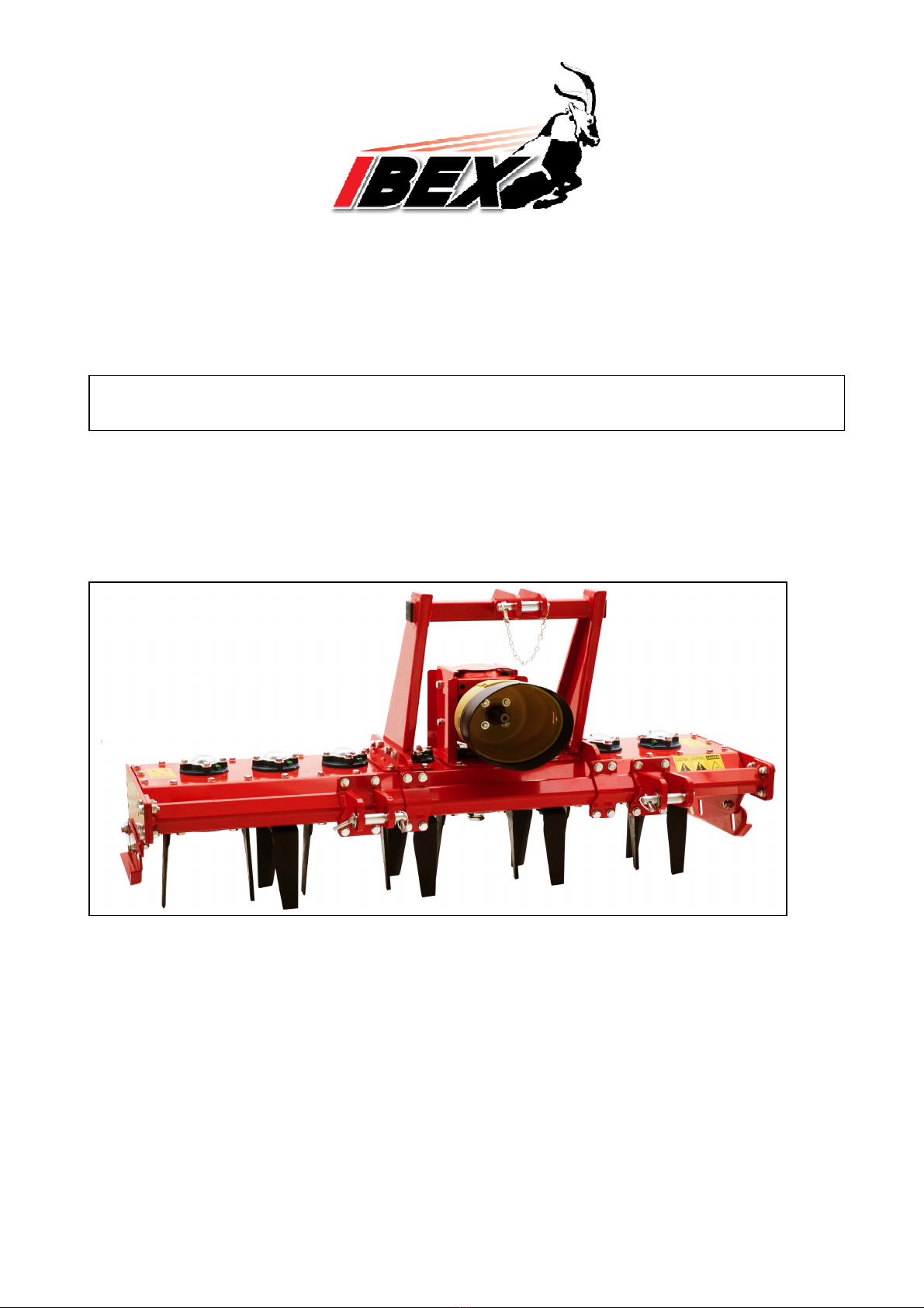
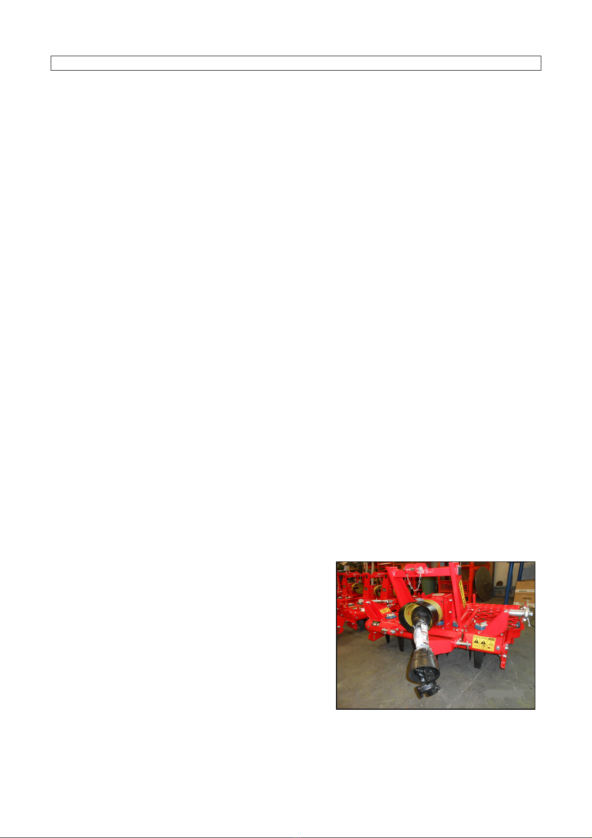
This manual is an integral part of the machine.
It must always accompany the machine and be kept within reach of the operator.
The enclosures mentioned are on integral part of this manual.
The purpose of this manual.
This manual gives information for the correct and safe use of the machine.
The owner must read this manual carefully before work with the machine.
Responsibility of the owner
The owner is responsible for accidents or damages caused to people or things due to negligence in following
the instructions in this manual.
Assistance in using this manual
Explanations: contact the dealer.
Request for additional copies of the manual: in case of loss or wear and tear, or in case one wants the
manual in a different language, the customer should ask the dealer or manufacturer.
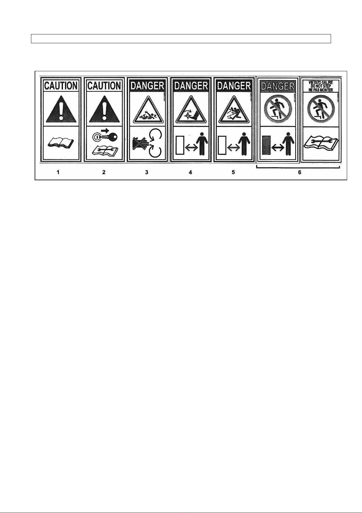
Pay attention to the warning signals
<Danger>: indicates a situation that is potentially dangerous which, if not avoided, will cause death or
serious damage.
<Warning>: indicates a situation that is potentially dangerous which, if not avoided, will cause death or
serious damage.
<Caution>: indicates a situation that is potentially dangerous which, if not avoided, can cause minor to
moderate damage or it indicates to be careful about an unsafe procedure.
<Important>: indicates instructions that must be followed precisely in order to avoid damage to the product,
process or environment.
<Note>: indicates supplementary information.

3
DESCRIPTION
F
UNCTION OF USE
The machine carries out all the function related with tools rotation in various work environment (open field,
vineyards, orchards, flower gardens, parks, vegetable gardens), in all type of ground whatever its
composition (sandy soil, medium mixture, clay) and consistency (crumbly, hard, semi-plastic) may be.
The use of a technical constructive concept trended to the search of high performances, reduction of troubles
and durability, improves the power/consumption ratio of the tractor thanks to the elasticity of the machine
frame, to the tools shape and to many original technical solutions.
P
ERFORMANCES
The machine is connected to the tractor by a 3°-point hitch which gives a movement of translation and a
cardan shaft connected to the PTO which gives a movement of translation to the tools carrier.
The working width is fix.
The working depth is adjustable by a rear roller.
The working area is fix.
P
ERFORMANCE LIMITS
Maximum forwarding speed: 5 km/h.
Speeds higher than the maximum can compromise the condition of the machine, the quality of the work
and the safety of the operator.
Maximum power applicable to the gear box: 20 kW ±5% at 540 g/min.
Higher power than one indicated, can damage irreparably the transmission gear box; especially during
heavy works.
Maximum working depth 180 mm.
S
TANDARD FEATURES
-Shear bolt cardan shaft.
V
ARIANTS & ACCESSORIES
-Wire roller.
-Cage roller.
-Spiked roller.
-Levelling blade.
-Seeder.

4
TECHNICAL SPECIFICATIONS
C
HARACTERISTICS FOR MODEL
Model
Type
Power
Working width
Weight
Maximum working
depth
Total width
N° of tools
HP KW cm. inch Kg. lbs.
cm. inch cm. inch n°
rotors
n°
teeth
TM60
150 30-50 22-38 150 60 248
546
18 7 155 60,9 7 14

5
SAFETY INFORMATION
G
ENERAL REGULATIONS
Only work in daylight.
The machine must not be used near people, especially children or animals.
Wear long pants and heavy shoes.
The protections are integral part of the machine: always work with the protections.
Pay attention using the machine on slopes: proceed to the maximum slope and never work in slanting
direction.
Before leaving the driver's seat, turn off the engine and disengage the transmission engine-shaft.
Check immediately the machine if it touches foreign objects.
Check immediately the machine if there are unusual strong vibrations.
Change quickly defective parts.
S
AFETY RESTRICTIONS
Children and people who are not familiar with these instructions must not be permitted to use the machine.
Local regulations can restrict the use of the machine in accordance to the age.

6
SAFETY SIGNS ON THE MACHINE
In this section, the safety signs on the machine are reproduced and explained.
1. Read the operator manual.
2. Disconnect the tractor key before maintenance and repair operations.
3. Stay at safety distance from PTO shaft.
4. Danger of flying objects. Stay at safety distance.
5. Danger. Stay at safety distance from blades.
6. Danger. Don’t climb on the machine
The safety signs on the machine must always be legible.
In case of damage, the labels of the signs must be replaced.
In the case of machine replacement parts that have safety signs, the signs must be replaced.
Supplying of new safety labels and the application procedure
Contact your dealer to receive new safety labels with instructions for application.

7
INSTRUCTIONS FOR USE
B
EFORE BEGINNING WORK
a) Connect the machine to the tractor as follows:
1. Insert the lifting arms of the tractor in the lower attachment points of the machine, lock by safety pin.
2. Connect the tractor linkage to the 3°-point hitch of the machine (triangle vertex), insert the pin and
lock with safety pin.
b) Check the gearbox and transmission oil level.
c) With the machine raised, go to the working area.
d) Connect the tractor PTO to the machine PTO.
e) Check that PTO chain is locked to prevent the protection sheet of PTO rotating.
B
EGINNING WORK
a) Keep people and animals at least 65 feet radius all around the machine.
b) Pull down the machine until the hoes touch the ground.
c) Connect PTO power and gradually bring it to 540 r.p.m
d) Pull down completely the machine and start to work.
A
T THE END OF WORK
a) Stop the tractor.
b) Raise the machine until the hoes goes out from ground.
c) Disconnect PTO power.
d) Disconnect tractor PTO from machine PTO.
e) Park the PTO shaft on the provided support.
f) Raise completely the machine

8
PROFESSIONAL SEEDER
S
EEDER SET UP
To empty the hopper, move lever “4” from position “C” to position “A”. After discharge of all seed move again
lever “4” to position “C”.
Fill the hopper with seed, now it is necessary to make set up of the machine considering how many Kg of
seed you want to sow each hectare. Refer to the below table operate as follow:
Seed type Set up
L
ever 1
Set up
Lever 2
Set up
Sluice gate 3
Wheat
10
2
Totally open
Corn
-
Pea
8
3
Totally open
Hemp
-
Sorghum
6
2
Totally open
Alfalfa
3
1
Half open
Onion
3
1
Half open
Depending on the type of seed, operate as follow:
1. Unscrew locking knob then adjust Lever “1” in correct position, screw docking knob.
2. Unscrew locking knob then adjust Lever “2” in correct position, screw docking knob...
3. Adjust position of Sluice gate “3” pulling in direction “A” to open or pushing in direction “C” to close.
Repeat adjustment on all Sluice gates.

9
To verify weight in Kg that will be sow (generally the weight in Kg per hectare related to each type of seed is
showed on technical sheet of the seed) operate as follow:
Model
Wheel turns
Fact
or K
150
25
400
Lift the seeder till the two wheels “W” and “W1” can turn free (picture 1).
Place a towel under the seeder spreader to collect the seed.
Turn the drive wheel “W” clockwise as showed by the arrow (picture 2) many times as showed on the above
table (choice your model).
Collect and weight the seed in the towel.
The seed weight multiplied per Factor “K” will be the total weight sowed per hectare.
In case of discrepancy respect to the desired weight, change position of Lever “1” and repeat weight
verification.
Picture 2
Picture 1

10
GRASS SEEDER
S
EEDER ADJUSTMENT
a. Fill the hopper with the seed then close the cover.
b. To set the quantity of seed that will fall. operate as follow:
1. Move the latch knob "A" in the desired position.
2. Rise the lock knob placed on the upper part of the lever "B" then turn the lever clockwise to
increase the quantity of seed that will fall, turn counter clock wise do decrease. To increase or
decrease the dosage, modify the position of the latch knob then move the lever.
To verify the weight (Kg) that will be sown (generally the correct quantity in kg per hectare is indicated on
seed bag), follow the instructions below:
Model
Rear
rol
l rotations
Factor K
1
50
16
400
Rise the seeder till the rear roll can turn free.
Place a towel under the seeder spreader to collect the seed.
Fill seed inside the seeder then turn the rear roll clockwise many times as showed on the above table,
choose the line that corresponds to your seeder model.
Collect and weight the seed in the towel.
The seed weight multiplied per Factor K will be the total weight sowed per hectare.
In case of discrepancy respect to the desired weight, act on the control level to increase or decrease the
seeder opening, then repeat weight verification.

11
MAINTENANCE INSTRUCTIONS
On diagram "A" the maintenances are indicated with their terms to effect on the machine.
Not follow the scheduled terms can compromise the functionality of the machine and in this case the
warranty is not applicable.
D
IAGRAM "A" SCHEDULED MAINTENANCE
FIRST
START
AFTER
10 HOURS
WORK
EVERY
30 H.
EVERY
500 H.
END OF
SEASON
BEGIN
WROK
END
WORK
MACHINE Greasing Greasing Greasing Cleaning
Gr
easin
g
Cleaning
GEARBOX Oil level Fill oil Fill oil Oil
replacement
TRANSMISSION
Oil level Fill oil Oil level Oil
replacemnet
SCREWS
Locking
Locking
TOOLS
C
heck
Check
Check
Check

12
1.
GREASING
At the scheduled time on diagram “A”, grease point “B”.
Greasing point is equipped with greaser HYDRAULIC TYPE MODEL "A" UNI 7663.
To greasing use only MULTIFUNCTIONAL GREASE LITHIUM BASED Type NLGI 2.
2.
O
IL LEVEL – OIL REPLACEMENT IN GEARBOX
At the scheduled time on diagram “A” verify the level and replace oil in the gearbox.
To fill oil use only OIL SAE 90.
Gearbox capacity: 1,1 L
a) To check the oil level in gear box, operate as follows:
1. With the machine on level unscrew the level plug "C" and check that oil touches lower hole rim.
2. If the level it's ok screw and lock plug "C".
3. If the level it's low, unscrew plug "D" and fill oil.
4. When the level it's ok screw and lock plugs "C" and "D".
b) To replace oil in the gearbox, operate as follows:
1. With the machine on level unscrew the level plugs “C”, "D" and “E” and drain completely oil.
2. Screw the plug “E”.
3. Fill new oil through the hole “D” up to oil touches lower hole rim “C”.
4. When the level is ok, screw the plugs “C” and “D”.
3.
O
IL LEVEL – OIL TRANSMISSION REPLACEMENT
At the scheduled time on diagram "A" check the level or replace oil in the transmission.
To fill oil use only OIL SAE 90.
Tank capacity: 5 L.
a) To check the oil in the transmission, operate as follows:
1. With the machine on level unscrew the plug "B" and check that oil touches lower hole rim.
2. If the level is ok, lock the plug "B".
3. If the level is low, fill oil.
4. When the level is ok, lock the plug “B”.

13
b) To replace oil in the transmission, operate as follows:
1. Unscrew the plug “B”, turn backward the machine and drain completely oil.
2. Introduce the new oil through the hole “B” up to oil touches lower hole rim.
3. When level is ok, lock the plug “B”.
4.
T
OOLS REPLACEMENT
a) To replace the tools, operate as follows:
1. Unscrews the two screws "A" which lock the tools to replace.
2. Take out the two screws and remove the tool “B”.
3. Place the new tool and the two screws “A”.
4. Lock the screws "A" with pneumatic wrench.
5. Repeat this operation for all the tools to replace.
ATTENTION: each rotor is equipped with a couple of right and left tools according to the position,
don’t invert the right tools with the left ones.

14
PROBLEMS SOLVING
TROUBLES CAUSES AND SOLUTIONS
Insufficient working depth -Decrease the forwarding speed
-Tools are not sharpened or damaged
Tools don’t penetrate
Rotary harrow bounces on the round and vibrates
-Broken or damaged tools
-Check the tools assembling
-Foreign objects between hoes - clean
-Decrease the forwarding speed
-Soil too dry and hard
Rotor compactness, obstruction
-Soil too wet
-Reduce working depth
-Increase number of revolutions of the rotor
Excessive tilling of the soil -Increase forwarding speed
- Decrease number of revolutions of the rotor
Poor tilling of the soil -Decrease the forwarding speed
-Increase number of revolutions of the rotor
Tools locking
Stones wedged between the tools
-Stop the tractor PTO
-Full rise the machine
-Stop tractor engine then remove the key from the
ignition
-Disconnect the machine from PTO shaft
-Remove the wedged stones
-Connect the PTO shaft to the machine then start
work

15
TRANSPORT
Except when working, moving the machine takes place when the machine is standing still and the
transmission is disconnected.
<Important>: keep speed low avoiding holes and ground roughness.
<Note> when on the road, obey existing traffic laws. Exhibit the signal signs on the rear ends. Respect any
local laws there may be.
<Operations> Lock the lifting bars of the tractor with the chain and tighteners. They must be parallel to the
bars.
STORAGE
Store the machine in a dry place that isn't dusty.
INFORMATION ON DEMOLITION
At the end of its working life, the machine must be sent to be demolished and that can only be done
by an authorized authority, in accordance with the national laws in force for the environment. Therefore, it is
necessary to get information from the qualified local authorities on the procedure to follow. The machine is
mainly composed of: iron materials, rubber and paints.
WARRANTY
The machine is covered by the manufacturer warranty for a period of 24 months.
The warranty is not applicable when:
a) The maintenance work has not been done correctly.
b) The machine has been used out of its own service.
c) The machine has been transformed or modified without the manufacturer's written authorization.

16
WORK AND MAINTENANCE SHEET
Every user should register on this sheet the facts about the life of the machine (both work and maintenance),
so as to attest its conditions.
DATE WORKING
HOURS
MAITENANCE NOTE USER

17
SPARE PART AND ACCESSORIES

18
TM60 MECHANISMS

19
TM60 SHEETS

20
TM60 LEVELLING BLADE
Table of contents
Other IBEX Farm Equipment manuals
Popular Farm Equipment manuals by other brands

Vicon
Vicon Extra 832R PRO instruction manual

Poettinger
Poettinger TOP 842 C Operator's manual

VALMETAL
VALMETAL STATIONARY UNROLLER Operator and parts manual

Checchi & Magli
Checchi & Magli WOLF PRO Use and maintenance manual

MacDon
MacDon R216 Unloading and assembly instructions

Dhollandia
Dhollandia DH-RMM 25 installation manual