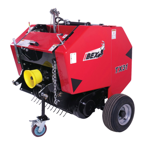
IBEX TX31 User manual

Operator’s Manual
Model: IBEX TX31 Mini Round Baler
ibexequipment.com
833-888-IBEX


Contents
1Introduction...............................................................................................................................................1
1.1 Conditions of Use .............................................................................................................................1
1.2 Machine Description .........................................................................................................................1
1.2.1 Pickup Lift Lever and Lock Arm ................................................................................................1
1.2.2 Pickup Lower Limit Chain .........................................................................................................1
1.2.3Shear Bolt..................................................................................................................................2
1.2.4 Pickup Drive Chain....................................................................................................................2
1.2.5 Bale Chamber ...........................................................................................................................2
1.2.6 Drive Chains..............................................................................................................................2
1.2.7 Hydraulic Power Pack...............................................................................................................2
1.2.8 Bale Density Control .................................................................................................................2
1.2.9 Full Bale Chamber Alarm..........................................................................................................2
1.2.10 Net Wrap Activation Lever ........................................................................................................2
1.2.11 Net Advancement Pulley, Brake, & Belt ...................................................................................2
1.2.12 Net Roll Tensioner and Tension Springs..................................................................................2
1.2.13 Bale Ejection .............................................................................................................................3
2Operator Safety ........................................................................................................................................6
2.1 Tractor Operation Safety ..................................................................................................................6
2.2 Implement Operation Safety.............................................................................................................6
3Tractor Connection...................................................................................................................................7
3.1 Thread the Net..................................................................................................................................7
3.2 Connect the Baler to the Three-Point Hitch......................................................................................9
3.3 Connect the PTO Shaft.....................................................................................................................9
3.4 Attach the Gate Lift Pull Rope and Net Pull Rope............................................................................9
3.5 Check Full Bale Chamber Alarm ....................................................................................................10
4Operation................................................................................................................................................11
4.1 Operational Adjustments ................................................................................................................11
4.1.1 Adjusting Net Roll Tension......................................................................................................11
4.1.2 Adjusting Pickup Height ..........................................................................................................12
4.1.3Adjusting Number of Wraps per Bale .....................................................................................12
4.1.4 Adjusting Bale Density ............................................................................................................13
4.1.5 Adjusting Tailgate Closing Speed...........................................................................................13
4.2 Operation Procedure ......................................................................................................................14
4.2.1 Initial Setup..............................................................................................................................14
4.2.2 Baling ......................................................................................................................................14
4.2.3 Recommendations for Good Results......................................................................................15
4.2.4 Finishing Work ........................................................................................................................15
5Maintenance...........................................................................................................................................16

5.1 Maintenance Safety ........................................................................................................................16
5.2 Maintenance Schedule ...................................................................................................................16
5.3 Routine Maintenance......................................................................................................................17
5.3.1 Pre-Work Lubrication ..............................................................................................................17
5.3.2 Roller Chain Tension...............................................................................................................17
5.3.3 Pickup Slip Clutch Tension .....................................................................................................18
5.3.4 Pickup Suspension..................................................................................................................19
5.4 End of Season Storage...................................................................................................................20
5.5 Beginning of Season.......................................................................................................................20

Ibex TX31 Mini Round Baler with Net Wrap - Operator’s Manual 1
1 Introduction
Congratulations on your purchase of the Ibex TX31 mini round baler with net wrap. Your machine, if
properly operated and maintained, will provide many years of productive use. The purpose of this manual
is to help you do this by describing proper safety, operation, and maintenance procedures. Do not attempt
to use the machine without thoroughly understanding the information contained in this manual. Contact
your Ibex dealer for assistance if any information described herein is not completely clear.
NOTE: All references made in this manual to right, left, front, rear, top and bottom is as viewed
facing the direction of forward travel with implement properly attached to tractor.
1.1 Conditions of Use
Your Ibex TX31 baler is designed to gather, compress, and bind crop materials such as hay, straw, and
pine straw, into easy to handle round bales. The machine performs best under certain conditions. Use of
the machine outside of those conditions could result in poor performance or damage to the machine.
The machine is designed to…
…work with tractors with 18 – 45 engine horsepower. Using this machine with a tractor that is outside
of the specified power range may result in damage or premature wear of the machine and/or sub-optimal
machine function.
…bale crop that is of optimal length. Crop material should not be excessively short (< 12”) or
excessively long (> 48”).
…bale hay that contains optimal moisture content. Hay should not exceed 20% moisture content.
…bale silage that contains optimal moisture content. Silage should contain between 50% and 60%
moisture content.
…work in a dry field. Do not attempt to use the machine immediately after rain or in a muddy field.
…be operated while exercising the safety instructions detailed in the “Operator Safety” section of
this manual.
1.2 Machine Description
1.2.1 Pickup Lift Lever and Lock Arm
The pickup is held in the raised position during transport using the lift lever (Figure 1, A) and is held in
place using the lock arm (B).
1.2.2 Pickup Lower Limit Chain
The lower limit chain (Figure 2, A) sets the minimum height of the pickup tines from the ground.

2 Ibex TX31 Mini Round Baler with Net Wrap - Operator’s Manual
1.2.3 Shear Bolt
The shear bolt (Figure 3, A) breaks to prevent damage to the machine in overload conditions. A set of
spare shear bolts are included with the machine (Figure 4).
1.2.4 Pickup Drive Chain
The pickup drive chain (Figure 5, A) transfers power to turn the pickup. The friction clutch (B) slips in
overload conditions to prevent damage to the pickup. Chain tension is controlled by the idler (C).
1.2.5 Bale Chamber
The bale chamber consists of multiple rollers that turn the bale and form it into a fixed-size cylindrical
shape (Figure 6).
1.2.6 Drive Chains
The baler’s rollers are turned by a series of drive chains (Figure 7, A). Tension springs (B) provide proper
tension to each chain. See Section 5.3.1 for chain tension specifications.
1.2.7 Hydraulic Power Pack
The baler raises the tailgate to eject the bale using a hydraulic cylinder. Hydraulic fluid is pushed into the
cylinder by the hydraulic power pack (Figure 8, A), which is powered by the rotating motion of the PTO
shaft which turns the roller chain (B).
1.2.8 Bale Density Control
The density sensor (Figure 9, A) can be positioned closer or further from the trigger (B) to vary bale
density. See Section 4.1.4 for details.
1.2.9 Full Bale Chamber Alarm
The full chamber horn (Figure 10, A) sounds when the bale chamber is full. It is powered by a 9V battery
(B).
1.2.10 Net Wrap Activation Lever
The net wrap activation lever (Figure 11, A) is used to initiate the process of wrapping the bale. See
Section 4.2.2, Baling, for details.
1.2.11 Net Advancement Pulley, Brake, & Belt
When beginning the bale wrapping process, the brake (Figure 12, A) is released from the belt (B), and the
pulley (C) turns the roller (D) that advances the net. More detail on the wrapping process is found in
Section 4.2.2, Baling.
1.2.12 Net Roll Tensioner and Tension Springs
The net roll tensioner (Figure 13, A) provides necessary force to keep the net roll in place and improve net
wrapping and cutting performance. See Section 4.1.1 for detail on adjustment of tension springs (B).

Ibex TX31 Mini Round Baler with Net Wrap - Operator’s Manual 3
1.2.13 Bale Ejection
The bale is discharged from the chamber by lifting the tailgate (Figure 14, A). Pulling the tailgate lift lever
(B) activates the hydraulic power unit (Figure 8, A) to retract the cylinder (Figure 14, C) to pull the gate
open. The gate remains open while the lever is pulled. Once the lever is released, the gate closes. The
bale ejector (Figure 15, A) rolls the finished bale far enough from the machine to allow the gate to close.
Figure 1 Top left side of baler
Figure 2 Front left side of baler
Figure 3 Left side of baler
Figure 4 Left side of baler

4 Ibex TX31 Mini Round Baler with Net Wrap - Operator’s Manual
Figure 5 Left side of baler
Figure 6 Rollers
Figure 7 Left side of baler
Figure 8 Right side of baler
Figure 9 Right side of baler
Figure 10 Top right side of baler

Ibex TX31 Mini Round Baler with Net Wrap - Operator’s Manual 5
Figure 11 Top right side of baler
Figure 12 Top left side of baler
Figure 13 Front of baler
Figure 14
Figure 15 Rear of baler

6 Ibex TX31 Mini Round Baler with Net Wrap - Operator’s Manual
2 Operator Safety
Your safety is important to us. Please carefully read and follow the instructions given below and contained
elsewhere in this manual before attempting to operate the machine. Most accidents can be avoided if you
fully understand and implement the safety practices discussed in this section.
WARNING: READ and UNDERSTAND all safety instructions in this section as well as
warnings, cautions, and important notes throughout the manual. Serious injury or death may
occur unless care is taken to follow these warnings.
2.1 Tractor Operation Safety
•READ and UNDERSTAND all safety instructions and warnings in the operator’s manual for your tractor.
•Understand how to stop forward motion, the engine, and the PTO of your tractor quickly in case of an
emergency.
•Do not allow an inexperienced person to operate the tractor or any attachments without supervision.
•Wear proper safety gear at all times.
•Do not operate the tractor while under the influence of alcohol or drugs. Consult a medical professional
regarding any prescription medications that you are currently taking and any side effects that could
hinder your ability to operate the tractor safely.
•Only operate a tractor that has been properly maintained.
•Only operate the tractor in conditions of clear visibility. Never operate in dark or foggy conditions where
visibility is restricted in front and to the sides of the tractor and implement. Ensure that all obstacles,
steep slopes in the terrain, and overhead obstructions are visible.
•The tractor must be equipped with a rollover protection system (ROPS) and seatbelts to ensure operator
safety in case of a rollover incident.
•Always set the parking brake and/or set the tractor transmission in parking gear, disengage the PTO,
stop the engine, and wait for all moving parts to stop before leaving the tractor seat.
•Do not operate the tractor or implement while hydraulic oil or fuel is leaking. Oil and fuel are explosive,
and their presence could present a hazard. Hydraulic lines are under extreme pressure and, if a break
occurs, bursting oil could cause skin injury and/or tissue damage. Turn off the engine and relieve
hydraulic pressure before checking for leaks.
2.2 Implement Operation Safety
•Keep body parts, clothing, jewelry, and anything else that is tethered to the body away from moving
parts on the baler to prevent entanglement, which could result in serious injury or death.
•Use extreme caution when performing repairs, maintenance, and when removing accumulated material.
•Use care to avoid striking solid objects such as fencing or sign posts. The impact could cause loss of
control of the tractor and implement, which could be hazardous.
•The baler must not be modified or altered, particularly with respect to the components that make up the
machine’s primary function.

Ibex TX31 Mini Round Baler with Net Wrap - Operator’s Manual 7
3 Tractor Connection
CAUTION: Only attach and detach the baler on a level surface. Always apply the parking brake
on the tractor when attaching an implement.
3.1 Thread the Net
Threading the net is simpler if done before attaching the machine to the tractor. Follow the steps below.
a) Disengage the net roll tension springs (Figure 16, A). Raise the roll tensioner (B) and lock it in the up
position by placing the support post (C) in the notch (D).
b) Place roll in the chamber so that the net feeds off of the top of the roll in front (Figure 17).
c) Feed the net down below the chamber (Figure 18) and under the roller below (A, hidden).
d) Pull on the net activation lever (Figure 19) to release the net advancement brake (Figure 20, A). If a
second person is available to assist, this person should continue to hold the lever forward through the
next steps. If working alone, use a wedge as shown in Figure 21 or a similar method to keep the brake
released.
e) Bring the net up and over the curved spreader bar near the top of the machine (Figure 22).
f) Ensure that the net is spread across the bar. Lay the net across the space between the rubber and
metal rollers. Use a meter stick, ruler, or similar shaped item to push the net down as evenly as possible
between the rollers while using your other hand to pull forward on the rubber roller until the net is
gripped and begins feeding down.
g) Continue turning the rubber roller until the entire width of net is fed down and is visible below the rollers.
The net cutting blades (Figure 23, A, hidden) may obstruct the net and cause it to bunch up. To remedy
this, pull forward on the net activation lever, which retracts the blade bar, and ensure that the net falls
straight down by very carefully pulling the strands of netting away from the blades.
CAUTION: The net cutting blades are sharp. Use care when placing hands near the blades.
h) Release the roll tensioner and place it on the roll (Figure 24). Install the tension springs in the
appropriate setting (see Section 4.1.1 for details on setting net roll tension).
Figure 16
Figure 17 Net feeds forward off top of roll

8 Ibex TX31 Mini Round Baler with Net Wrap - Operator’s Manual
Figure 18 Front of baler – net roll chamber
Figure 19 Top right side of baler
Figure 20 Top left side of baler
Figure 21 Top right side of baler
Figure 22 Top of baler
Figure 23 Top of baler

Ibex TX31 Mini Round Baler with Net Wrap - Operator’s Manual 9
Figure 24 Front of baler
3.2 Connect the Baler to the Three-Point Hitch
a) Attach and secure the tractor’s lift arms to the two lower pins on the baler.
b) Raise the lift arms slightly to remove weight from the stand and then raise the stand, securing it with the
linchpin.
c) Raise or lower the lift arms to tilt the baler until the top of the baler is level with the ground.
d) Adjust the tractor top link until it aligns with the top link mounting holes on the baler and secure with top
link pin.
e) Tighten sway chains on the tractor’s lift arms to center the baler and prevent lateral movement.
3.3 Connect the PTO Shaft
NOTE: If attaching the baler to the tractor for the first time, please note that the PTO shaft may
need to be shortened. See our PTO Shaft Cutting Guide for details.
Connect both ends of the shaft by pushing in the locking pin and sliding the yoke onto the PTO of the
tractor and baler. Push until the locking pin releases and settles into the groove. Attach the cover’s safety
chains to a stationary part of the tractor. Leave some slack in the chain to accommodate pivoting
movements.
3.4 Attach the Gate Lift Pull Rope and Net Pull Rope
Attach the ends of the ropes to the gate lift lever and net activation lever, respectively, if not already
attached. Tie the other ends of the ropes to the tractor’s ROPS bar or somewhere inside the cab for easy
access during work.
CAUTION: Leave some slack so that the ropes do not become taught during regular operation,
but not so loose that it becomes entwined in the PTO shaft or other moving parts.

10 Ibex TX31 Mini Round Baler with Net Wrap - Operator’s Manual
3.5 Check Full Bale Chamber Alarm
Test the function of the full chamber horn by depressing the activation switch (Figure 25, A). If the horn
does not sound, try replacing the 9-volt battery and test it again.
CAUTION: Do not operate the baler without a working full chamber horn.
Figure 25 Right side of baler

Ibex TX31 Mini Round Baler with Net Wrap - Operator’s Manual 11
4 Operation
The purpose of this section is to instruct you on the safe and optimal use of your TX31 baler. Pictures are
included for illustrative purposes but may not match your machine exactly. Some pictures show protective
covers removed for purposes of clarity. DO NOT attempt to operate the machine while the protective
covers are removed.
Every operator of the implement, whether it is you or someone else, must be completely familiar with this
section before attempting to use it.
4.1 Operational Adjustments
4.1.1 Adjusting Net Roll Tension
The amount of tension placed on the roll of net wrap is crucial to proper functioning of the wrapping
mechanism. If the tension is too light, the net will not be tightly drawn, which often results in poor cutting. If
it is too heavy, the roller may not be strong enough to pull and unravel the net and/or the bale may not be
able to grip the net after it is fed down into the chamber. Follow the guidelines below to set the proper
tension.
•Tension is adjusted by the placement of two tension springs (Figure 26, A) among several position
holes (B). Holes closer to the front of the machine extend the spring and provide greater tension, and
vice versa.
•A new roll of netting will require a lower tension setting (a hole closer to the rear of the machine) than
a partially used roll. The tension must be adjusted periodically as the roll diameter decreases.
•The larger the diameter and the heavier the roll, the lower the tension should be. Springs may need to
be disengaged completely for a new extra large roll of net to unravel properly.
•Optimal positioning of the tension springs will vary depending on several factors, including:
►Roll size & weight
►Bale density
►Type of baled crop
►Moisture content of baled crop
►PTO speed used
►Environmental conditions
•In humid conditions, talc powder dry lubricant can be applied to the edge of the roll to reduce tension,
which will ensure the roll feeds net consistently and the net is cut consistently (Figure 27).
Figure 26 Left side of baler
Figure 27 Applying talc powder to front of net roll

12 Ibex TX31 Mini Round Baler with Net Wrap - Operator’s Manual
4.1.2 Adjusting Pickup Height
•For optimal operation, the tines of the pickup should be about one (1) inch from the ground in normal
conditions. In bumpy or rocky fields, a clearance of up to two (2) inches or more may be suitable to
prevent damage to pickup components. For baling light hay cuttings or straw, the pickup may need to
be lowered.
•Adjust the pickup height by lifting it with the lift lever (Figure 28, A) and using the lower limit chain (B) to
keep it in place.
•The pickup may be lifted and locked in the transport position by means of the lift lever and transport lock
(Figure 29, A).
Figure 28 Front left side of baler
Figure 29 Front left side of baler
4.1.3 Adjusting Number of Wraps per Bale
•Netting is continuously unraveled from the roll until it is cut, therefore adjusting the timing of the cut will
determine how much net is wrapped around each bale.
•This timing is metered in two ways:
a. The metering knife (Figure 30, A) travels along the threads of the metering rod (B) as the
wrapping process takes place. The longer it stays on the rod, the more net will unravel and wrap
around the bale. The rod can be turned and extended outward from the machine to achieve a
longer metering period and thus more wraps on the bale. The opposite is also true.
b. The amount of net on the bale can be increased on the fly if the operator engages the activation
lever for a longer period of time. See Section 4.2.2 to learn more about the wrapping procedure.
Figure 30 Right side of baler

Ibex TX31 Mini Round Baler with Net Wrap - Operator’s Manual 13
4.1.4 Adjusting Bale Density
•The baler creates bales of uniform size and shape, but can produce lighter or denser bales.
•Density is controlled by the position of the density sensor (Figure 31, A). The sensor can be mounted
closer or further away from the trigger plate (B). Mounting the sensor closer to the trigger plate will
sound the bale full alarm earlier and vice versa.
•In general, dryer hay and straw will require a higher density setting for best performance, while hay with
higher moisture, and especially green hay, should be set at a lower density.
•When increasing density, always change the position of the sensor gradually until you reach the desired
bale density. Drastic changes in sensor position could result in bales that are too light or too heavy.
Bales that are too light may be difficult to wrap, and bales that are too heavy may result in shearing of
the protective shear bolt.
Figure 31 Right side of baler
4.1.5 Adjusting Tailgate Closing Speed
•The opening and closing action of the tailgate can be slowed down or sped up to suit your preference by
adjusting the position of the flow control valve (Figure 32, A).
•Hydraulic flow can be stopped for maintenance or other purposes by turning the stop valve (B) upward
so that it is perpendicular to the cylinder.
Figure 32 Top rear of baler

14 Ibex TX31 Mini Round Baler with Net Wrap - Operator’s Manual
4.2 Operation Procedure
4.2.1 Initial Setup
1. Attach the baler to the tractor as discussed in Section 3.
2. Unlatch the pickup lever lock and lower the pickup. Adjust the height of the pickup with the chain so that
the tines are approximately one (1) inch from the ground at their lowest point. For very long grass, the
height may be raised to help avoid dirt mounds. For very short grass and cut straw, the pickup may
need to be lowered some for good results. Avoid continual contact with the ground, as this will result in
dirty hay and will reduce the life of the pickup tines.
3. Adjust the net roll tension as necessary (see Section 4.1.1).
4. Attach the tailgate pull rope and the net activation rope to the tractor’s roll bar or to the interior of the
tractor’s cab so that the ropes can be easily grasped but are not tight.
5. To ensure optimal net cutting performance, perform pre-work lubrication as described in Section 5.3.1.
4.2.2 Baling
1. Line up to straddle the first windrow. Lower the engine speed to an idle, engage the tractor’s power
take-off (PTO), and then gradually bring the engine RPM up to achieve 540 RPM PTO speed. The PTO
should remain engaged during all baling activity.
2. Drive over the windrow and begin picking up the hay or straw. Optimal baling speed will be 2-3 miles per
hour, or about a slow walk. The best speed will depend on field conditions and windrow size.
3. Keep an eye on the pickup to make sure the crop is being pulled in by the baler and is not collecting in
front of the baler. If material accumulates in front of the baler, stop or slow down until the baler can
catch up, and then proceed.
4. Continue forward until the horn sounds. When you hear the horn, stop forward motion.
5. Pull on the net activation rope with a firm tug and hold the rope for three full seconds. Pulling on the
rope will engage the tensioner for the net activation belt (Figure 33, A). If the rope is not pulled firmly,
there may not be enough tension on the belt to advance the net. After three seconds have passed,
release the rope. The net will continue to unravel for a short period of time and will eventually be cut
automatically. When this happens the net wrapping procedure is finished.
6. Pull on the tailgate lift rope to raise the tailgate and eject the bale. Release the rope once the bale has
rolled away from the machine. The door will close on its own.
Figure 33 Left side of baler

Ibex TX31 Mini Round Baler with Net Wrap - Operator’s Manual 15
4.2.3 Recommendations for Good Results
•While transporting the baler between uses, raise the pickup and lock it in the transport position.
WARNING: Transporting the baler without the pickup locked in transport mode may strain
and damage the lower limit chain.
•Faster PTO speeds, closer to 540 RPM, will result in fewer problems with bale wrapping and net cutting.
The opposite is true as well – slower PTO speeds may result in inconsistent wrapping success.
•Attempting to bale hay (not haylage or silage) exceeding 20% moisture content will not only result in
problems with mold or potential spontaneous combustion, it is also can be difficult to bale. Wet hay is
denser and can more easily overload the baler if the density setting is not adjusted so that it is on the
lighter end. If baling regular hay, be sure to test the moisture content with an accurate moisture meter. If
baling hay for silage/haylage, be sure to adjust the density to a low setting and only increase it gradually
if necessary.
•In general, traveling at a lower forward speed while baling will result in a higher density bale.
•The optimal windrow will have a width of 28-32 inches and a height of 12-16 inches. The more uniform
the windrows, the smoother the operation will be and the more consistent the bale weights will be.
•Many problems can be traced to very short material and/or material that is too dry. Hay is best baled
when it is 1-3 feet tall, with approximately 15% moisture content. Very dry hay will result in lightweight
and inconsistent bales and may often cause problems with bale wrapping. If baling very dry hay and the
net does not continue to feed after releasing the activation arm, drive forward a few feet, adding more
hay into the chamber. Additional hay in the chamber may provide enough tension to grip the net that
has been fed down. Using a higher density setting may also be required when baling very dry material.
•To avoid misshapen bales, crop should be evenly distributed across the full width of the baler pickup.
For very small windrows, it may be necessary to weave to the left and right while baling to make sure
edges of bales are fully formed.
4.2.4 Finishing Work
The following steps should be taken at the end of each day of work. Additional steps are needed if the
machine is being stored away for the off-season. See Section 5.4.
1. Shut the implement down by gradually lowering the throttle on the tractor to idle speed before turning off
the PTO.
2. Position the implement in its storage location, on level ground.
3. Place the transmission in Park or Neutral, set the parking break, and turn the engine off.
4. If the baler is lifted off the ground, lower the tractor’s lift arms until the baler’s tires contact the ground.
Raise or lower the three-point hitch slightly until pressure is off the top link pin, then remove the top link
from the baler.
5. Lower the parking stand on the baler and secure it in place with the locking pin. Raise the lift arms if
necessary to provide room for the parking stand to go all the way down.
6. Disconnect tailgate and net wrap activation ropes from the tractor.
7. Chock the baler’s wheels, disconnect the machine from the tractor’s lower lift arms, disengage the PTO
shaft from the tractor, turn the tractor back on, and drive forward and away from the implement.
8. Perform daily maintenance. See the Maintenance Schedule in Section 5.2.

16 Ibex TX31 Mini Round Baler with Net Wrap - Operator’s Manual
5 Maintenance
5.1 Maintenance Safety
•Never attempt to lubricate, adjust, or remove material from the baler while it is in motion or while tractor
engine is running.
•Wear protective gear such as goggles and gloves if using high pressure air or water to clean the baler.
•Always perform maintenance with the machine positioned on a level surface.
5.2 Maintenance Schedule
Action
Interval
Specifications
As Needed
Each Day
of Use
100 Hrs. or
Ea. Season
LUBRICATION
Gearbox – change oil
X
Gear oil: SAE 90, GL-5
Hydraulic pump – change oil
X
Hydraulic Fluid, 1.8 qt.
Chain drive sprocket – grease
zerk X X
NLGI No. 2 Grease
PTO shaft – lubricate
X X
Lubricate according to PTO
shaft manual
Pivot points without bearings
– lubricate X X
Spray a penetrating
chain/cable lubricant
Roller chains – lubricate
X X
Spray a penetrating
chain/cable lubricant
GENERAL MAINTENANCE
Check nut/bolts – tighten any
that are loose X X
Roller chains – tighten any
that are loose X X
See Section 5.3.1
Tire air pressure – check and
inflate X X
Maximum pressure: 28 psi
Operational adjustments
X X
Carry out as specified in
Section 4.1
General machine cleaning
X X
Remove visible dirt/debris.
Do not use pressured water.
Use caution with
compressed air.
Full bale chamber alarm horn
battery – replace X X
9V battery
Electrical wires – inspect for
wear and replace as needed X X
Thorough machine cleaning
X
Clean as discussed in
Section 5.4
Bare metal: apply paint or
grease to prevent rust X
Other manuals for TX31
5
Table of contents
Other IBEX Farm Equipment manuals
Popular Farm Equipment manuals by other brands

AGROFROST
AGROFROST Frostbuster F501 Operating & maintenance instructions

GREAT PLAINS
GREAT PLAINS Terra Max HT1110-6.0M Operator's manual

Worldwide Construction And Forestry Division
Worldwide Construction And Forestry Division 410J Technical manual

paladin
paladin FFC LAF5647 Operator and parts manual

Tatu Marchesan
Tatu Marchesan GCRO 7010 instruction manual

Rabe
Rabe Raven Avant Series Operating instruction