IBEX TS51C User manual

ASSEMBLY GUIDE
TS51C Drum Mower

ASSEMBLY GUIDE
2021-1.2 IBEX EQUIPMENT CO. 1
TS51C Drum Mower
CONTENTS
Scope and Purpose ................................................................................................................. 3
Uncrating................................................................................................................................ 3
Guard Installation................................................................................................................... 5
Three Point Hitch.................................................................................................................... 6
Blade Installation.................................................................................................................... 7
Attaching the Drum Unit to the 3 Point Hitch......................................................................... 9
Attaching the Drum Unit ...................................................................................................... 13
Transport Lock...................................................................................................................... 15
PTO SHAFTS.......................................................................................................................... 15
PTO Shaft Safety................................................................................................................... 17
Pivot Restrictor..................................................................................................................... 17
Guard Installation................................................................................................................. 18
Safety Release (“Breakaway Bar”) ........................................................................................ 20
Lubrication ........................................................................................................................... 21
Figure 1 lifting the drum assembly............................................................................................. 3
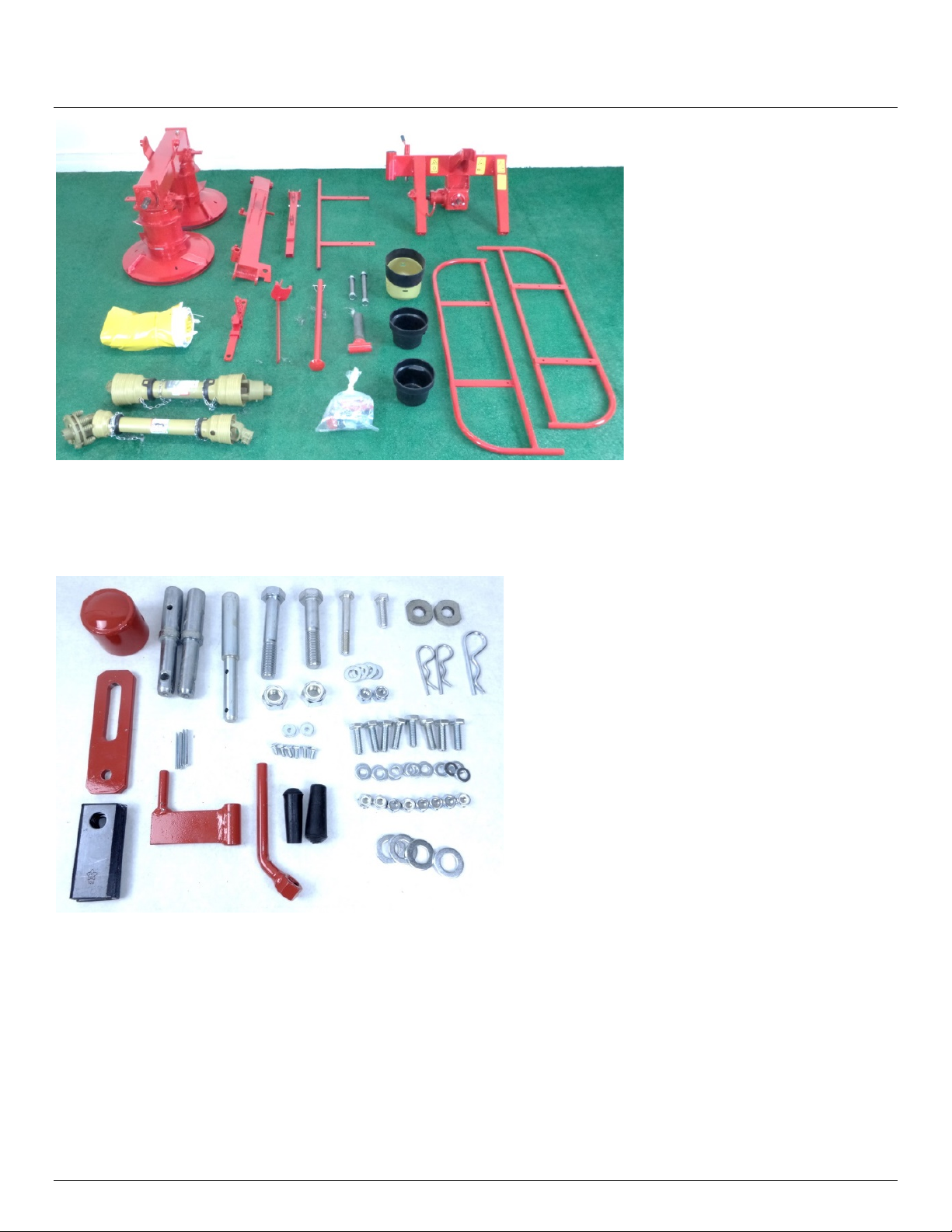
Figure 2 parts ready to assemble. .............................................................................................. 4
Figure 3 hardware sorted out. ................................................................................................... 4
Figure 4 larger guard installed on the gearbox facing the tractor .............................................. 5
Figure 5 the smaller guard with the cut-out facing the rear (cutout may look different on your
machine).................................................................................................................................... 5
Figure 6 the other small guard installed on the drum unit......................................................... 6
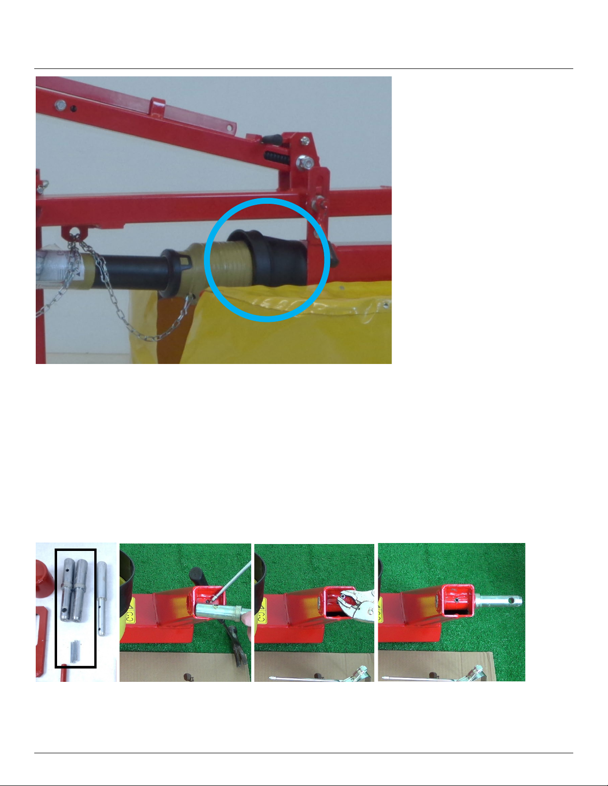
Figure 7 install the pins in the arms as shown on both sides...................................................... 6
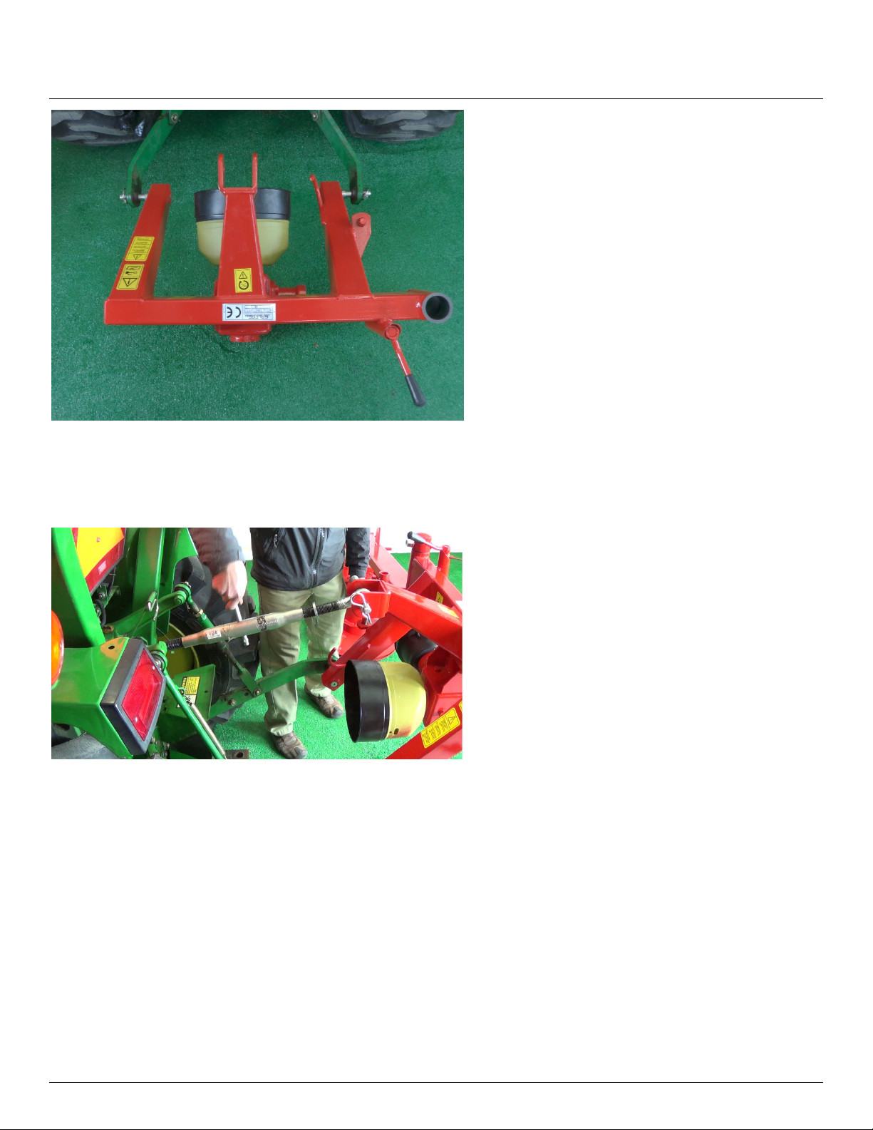
Figure 8 attached to lift arms..................................................................................................... 7
Figure 9 level the 3 point hitch unit with the top link................................................................. 7
Figure 10 blade tool ................................................................................................................... 8
Figure 11 installing a blade ........................................................................................................ 8

ASSEMBLY GUIDE
2021-1.2 IBEX EQUIPMENT CO. 2
Figure 12 move the drum unit over to the three point hitch assembly like this ......................... 9
Figure 13 swivel tee assembly.................................................................................................... 9
Figure 14 the cap and hardware are shown here for the swivel tee ........................................ 10
Figure 15 swivel tee in place for next step ............................................................................... 10
Figure 16 short swivel pin ........................................................................................................ 11
Figure 17 align holes in arm to swivel tee ................................................................................ 11
Figure 18 holes aligned to allow pin to pass............................................................................. 12
Figure 19 pin through and nut started ..................................................................................... 12
Figure 20 top spring arm installed with pin blocked up by using a 2x4 .................................... 13
Figure 21 hardware to attach spring arm to lower arm............................................................ 13
Figure 22 top spring arm attachment to lower arm ................................................................. 13
Figure 23 push the lower arm down to line up with drum unit................................................ 14
Figure 24 holes are close to being aligned ............................................................................... 14
Figure 25 nut and washer installed on pivot pin ...................................................................... 15
Figure 26 transport lock and rubber grip installation............................................................... 15
Figure 27 connect the driveline with one-way clutch............................................................... 16
Figure 28 guard chains attached .............................................................................................. 16
Figure 29 shaft with slip clutch end.......................................................................................... 16
Figure 30 restrictor plate with hardware ................................................................................. 18
Figure 31 pivot restrictor plate and handle shown installed from side .................................... 18
Figure 32 front guard has six holes .......................................................................................... 19
Figure 33 eight sets of fasteners used for attaching guard frame ............................................ 19
Figure 34 curtain installed with 2 holes for toe guard facing forward...................................... 19
Figure 35 curtain straps secure to the guard frame ................................................................. 20
Figure 36 safety release bar ..................................................................................................... 20
Figure 37 correct oil level in drum gearbox.............................................................................. 21

ASSEMBLY GUIDE
2021-1.2 IBEX EQUIPMENT CO. 3
SCOPE AND PURPOSE
This guide is limited to Ibex TS51C drum mowers (also labeled with the original manufacturer
model name, Galfre FR/G 130). The guide covers models manufactured in 2020 and forward.
This manual is a guide to aid in the assembly only. Consult the Quick Start Guide and User
Manual for instructions on usage and safety.
UNCRATING
Heavier components can be lifted out of the crate, using lift straps or chains, if a lift is
available.
Figure 1 lifting the drum assembly
If no lift is available, the crate will need to be cut open for easier access. Remove the smaller
parts, then slide the drum unit out of the crate onto the ground. The drum mower bottom
skids drag across the ground during use, so it is alright to drag them to the location that you
plan to use for assembly.
Lay out the parts so you can see everything in one place.

ASSEMBLY GUIDE
2021-1.2 IBEX EQUIPMENT CO. 4
Figure 2 parts ready to assemble.
Take the bag of parts and sort them out in like groupings. It makes finding the hardware much
easier during assembly.
Figure 3 hardware sorted out.
Grease the PTO drivelines before assembly. Also grease the plastic fittings on the free rotating
plastic guards. It’s much easier to do before assembly. Consult the driveline manuals that are
attached to the PTO drivelines for instructions on lubrication. Keep the driveline manuals for
future reference.

ASSEMBLY GUIDE
2021-1.2 IBEX EQUIPMENT CO. 5
GUARD INSTALLATION
Install the plastic PTO guards as shown in the images that follow. They are easier to install
before assembling the mower.
The larger guard is installed on the gearbox facing the tractor.
Figure 4 larger guard installed on the gearbox facing the tractor
The smaller guard with a cutout is installed on the 3 point hitch gearbox on the other side,
with the cutout facing the rear. This cutout provides space to allow the PTO shaft to pivot to
90 degrees when the mower is switched to transport mode.
Figure 5 the smaller guard with the cut-out facing the rear (cutout may look different on your machine)
The other small guard without a cutout is installed at the drum unit PTO spline.

ASSEMBLY GUIDE
2021-1.2 IBEX EQUIPMENT CO. 6
Figure 6 the other small guard installed on the drum unit
THREE POINT HITCH
The 2 lift pins must be secured to the 3 point hitch. Position the three point hitch so the two
arms face up. Find the two lift pins and the 2 smaller roll pins (spring pins) shown below. Oil
the holes in the pins and the hitch then oil the roll pin. Secure the roll pin with locking pliers
and drive through the holes with a hammer. The pins can be installed in a different
configuration than shown, for example if the width of your tractor’s lift arms is narrow, you
may want to install the pins facing inward.
Figure 7 install the pins in the arms as shown on both sides
Move the 3 point hitch assembly over to the back of your tractor. Attach to the tractor lift
arms and install the lynch pins.

ASSEMBLY GUIDE
2021-1.2 IBEX EQUIPMENT CO. 7
Figure 8 attached to lift arms
Lift the 3 point hitch unit up and install the top link pin. Adjust the length of the top link to
make the 3 point hitch close to straight up and down.
Figure 9 level the 3 point hitch unit with the top link
BLADE INSTALLATION
The 6 cutting blades that come with the mower are installed and changed with the blade tool.
The blade tool is stored on the top of the spring arm that connects the 3 point hitch to the
drum unit, shown here fully assembled.

ASSEMBLY GUIDE
2021-1.2 IBEX EQUIPMENT CO. 8
Figure 10 blade tool
Install the blades so that the angled edges are sloped downward. Position the blade tool so
that the two identical prongs are inserted between the two discs of the drum. Then raise the
arm so that the pin of the tool inserts into the slot on the upper disc. Pivot the tool up until
there is sufficient clearance, install the blade, and let the tool arm down.
The drum unit may need to be raised higher in order to have enough clearance to angle the
tool so that the two prongs fit below the upper disc. Once installed, be sure the blade is on the
pin and swings freely.
For safety purposes, never place your hand or fingers inside the opened space between the
discs.
Figure 11 installing a blade

ASSEMBLY GUIDE
2021-1.2 IBEX EQUIPMENT CO. 9
ATTACHING THE DRUM UNIT TO THE 3 POINT HITCH
Place the drum unit so that it is oriented as shown in Figure 12. Be sure the PTO spline shafts
face each other.
Figure 12 move the drum unit over to the three point hitch assembly like this
You will use the swivel tee subassembly shown below to connect two lift arms to the three
point hitch assembly.
Figure 13 swivel tee assembly

ASSEMBLY GUIDE
2021-1.2 IBEX EQUIPMENT CO. 10
Figure 14 the cap and hardware are shown here for the swivel tee
Put the swivel tee through the hole, without the cap, so that the cap goes on top. Install the
nut & bolt only until you feel some resistance – don’t tighten all the way as the bolt will need
to come back out to mount the top arm later. You will need either an adjustable wrench or a
30mm socket to secure the nut.
Figure 15 swivel tee in place for next step

ASSEMBLY GUIDE
2021-1.2 IBEX EQUIPMENT CO. 11
Next get the shorter of the two swivel pins as seen in Figure 16. It usually has the washer and
nut attached.
Figure 16 short swivel pin
Align the two holes on the support arm so that they centered to the bushing. The pin will not
go through and the plastic bushings could be damaged if the holes are not well aligned first.
You can use an adjustable height stand such as a chair to hold up the arm while aligning the
holes. Take note of the orientation of features so that it is installed right side up.
Figure 17 align holes in arm to swivel tee
Adjust the centers of the holes to be concentric and well-aligned before attempting to push
the pin through.

ASSEMBLY GUIDE
2021-1.2 IBEX EQUIPMENT CO. 12
Figure 18 holes aligned to allow pin to pass
Drive the pin through. Fit the washer and the nut. The nut takes a 30mm wrench. Do not over
tighten, just snug. Use a screwdriver, or something that will fit through the hole in the round
head to keep the pin from turning.
Figure 19 pin through and nut started
The top spring arm will fit onto the top cap as shown. Again, do not over-tighten as it needs to
be able to pivot.Before removing the bolt from the top cap, raise the three point hitch on the
tractor and cut a 2 foot length of 2x4 to support the lower arm. Let the three point hitch down
so it is resting on the 2x4. This way the pin will not fall out of the hole when the hardware is
removed on the top.

ASSEMBLY GUIDE
2021-1.2 IBEX EQUIPMENT CO. 13
Figure 20 top spring arm installed with pin blocked up by using a 2x4
Next, get the hardware to secure the spring arm to the lower lift arm as shown in Figure 21.
Figure 21 hardware to attach spring arm to lower arm
Connect the lower arm to the top arm as shown in Figure 22. Be sure the bolt goes through
the loop on the spring inside the top arm. The lower arm will need to be raised up at an angle
to line everything up.
Figure 22 top spring arm attachment to lower arm
ATTACHING THE DRUM UNIT
Position the drum unit so that the center pivot holes line up when the arm assembly is pushed
down. If you are working by yourself, using a ratchet strap to pull down the spring loaded arm
will make this operation easier.

ASSEMBLY GUIDE
2021-1.2 IBEX EQUIPMENT CO. 14
Figure 23 push the lower arm down to line up with drum unit
The centers must be lined up before driving the pin through the hole. Use a long screwdriver,
long punch, or something similar to line up the holes. Do not force the pin through, as you can
damage the plastic bushings. A little oil on the pin can help. Use the top link to adjust the angle
and adjust the three point hitch height on the tractor to better line up the holes. Use patience
as the pin will not go through easily until it is lined up well. Try nudging the drum unit to get all
holes aligned at the same time.
Figure 24 holes are close to being aligned
Install the washer and nut on the pivot pin. The nut is a nylon locking nut and should not be
over-tightened.

ASSEMBLY GUIDE
2021-1.2 IBEX EQUIPMENT CO. 15
Figure 25 nut and washer installed on pivot pin
TRANSPORT LOCK
Install the transport lock for the spring arm as shown. Use a mallet to drive the rubber grip
over the pin as shown. There are two rubber grips. Use the smaller of the two.
Figure 26 transport lock and rubber grip installation
PTO SHAFTS
The PTO shaft with the one-way clutch shown in the picture below is installed between the 3
point hitch and the drum unit. Install the thicker clutch end so that it is attached to drum unit
(see Figure 27).

ASSEMBLY GUIDE
2021-1.2 IBEX EQUIPMENT CO. 16
Figure 27 connect the driveline with one-way clutch
Attach the PTO shaft guard chains as shown in Figure 28 so that the guards do not spin.
Figure 28 guard chains attached
The driveline with the slip clutch is attached between the 90 degree gearbox and the tractor.
The slip clutch (the wider end with the springs) attaches to the mower, while the other end
attaches to the tractor.
Figure 29 shaft with slip clutch end

ASSEMBLY GUIDE
2021-1.2 IBEX EQUIPMENT CO. 17
As with any new implement, the shaft that attaches to the tractor may need to be cut to
length. Consult the included Ibex Equipment PTO Shaft Cutting Guide.
PTO SHAFT SAFETY
Read the manuals that are supplied with your PTO’s before operating the machinery. Failure
to follow all safety procedures in the manufacturer’s literature could lead to equipment
damage, personal injury or death.
The primary PTO shaft is supplied long because the length of the draw arms on tractors vary. It
is typical to have to remove excess length from the PTO before using the implement with your
tractor. If you have more than one tractor, it is important to cut the shaft for the tractor you
will be using the implement with. Mark the PTO with permanent marker as to which tractor it
is to be used with to avoid confusion that could lead to damage. Using a PTO shaft that is too
short can cause the PTO to separate during use that could lead to damage of personal injury.
The PTO shaft must never completely collapse in use, because to do so would put the weight
of the implement attached to the tractor pushing against the PTO’s of the tractor and
implement. The output bearings are not designed for thrust forces pushing the PTO forward
into the gearbox, and could cause severe damage. This could be an expensive repair on the
tractor if the PTO bearings or gearing were damaged due to an improperly fitted PTO shaft. If
you have to lift the implement to attach the PTO, then the PTO shaft is too long and must be
cut.
The PTO shaft going to the tractor should have 2 inches of space to retract when the distance
between the splines on the tractor and implement are at minimum. If this is not the case, the
PTO must be cut to avoid damaging the tractor or the PTO shaft. If you need to cut the PTO
shaft, see the instructions that came with the shaft.
PIVOT RESTRICTOR
The drum unit rests on the ground and pivots to adjust to the terrain while cutting. The pivot
restrictor keeps the mower from pivoting too far and also secures it while in transport mode.
Gather the parts shown in Figure 30. Install the mounting bolt with its head facing out, as
shown, as the clearance with the handle is tight.

ASSEMBLY GUIDE
2021-1.2 IBEX EQUIPMENT CO. 18
Figure 30 restrictor plate with hardware
Install two each of the odd-shaped thick washers and smaller flat washers as shown in Figure
31. Any additional small flat washers are spares. The handle (“pivot restrictor handle”) should
be tightened during transport only. During mowing, the handle is loosened so that the mower
pivots freely within the range allowed by the slot in the restrictor plate.
Figure 31 pivot restrictor plate and handle shown installed from side
GUARD INSTALLATION
The front guard frame has 6 holes and a pin that slides into the tubing of the rear frame as
shown.

ASSEMBLY GUIDE
2021-1.2 IBEX EQUIPMENT CO. 19
Figure 32 front guard has six holes
The eight sets of hardware shown in Figure 33 are used to fasten the guard frames. Align the
pin in the front frame to the hole in the rear frame, then bolt on. Do not install the optional
bumper guard yet (the double-T shaped frame seen in Figure 34), as the curtain must be fitted
first. You will need two wrenches that are 17mm for these nuts and cap screws.
Figure 33 eight sets of fasteners used for attaching guard frame
You can now install the optional bumper guard if desired. The bumper guard can help
somewhat to cut certain taller crops more efficiently. Slots must be cut out of the curtain to
accommodate the two mounting bars as shown in Figure 34.
Figure 34 curtain installed with 2 holes for toe guard facing forward
Other manuals for TS51C
3
Table of contents
Other IBEX Farm Equipment manuals