IBEX TS51C User manual

ASSEMBLY GUIDE
TS51C Drum Mower

ASSEMBLY GUIDE
2022-1.1 IBEX EQUIPMENT CO. 1
TS51C Drum Mower
CONTENTS
Scope and Purpose ................................................................................................................. 3
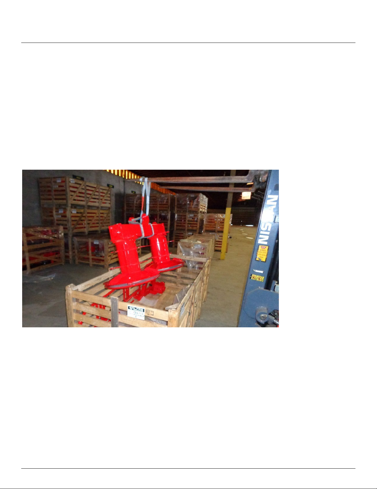
Uncrating................................................................................................................................ 3
Hardware Guide......................................................................................................................... 4
PTO Guard Installation............................................................................................................ 4
Three Point Hitch.................................................................................................................... 3
Blade Installation.................................................................................................................... 4
Attaching the Drum Unit to the 3 Point Hitch......................................................................... 6
Transport Lock...................................................................................................................... 10
PTO Shafts ............................................................................................................................ 10
Pivot Restrictor..................................................................................................................... 12
Guard Installation................................................................................................................. 14
Safety Release (“Breakaway Bar”) ........................................................................................ 15
Lubrication ........................................................................................................................... 16
Figure 1 lifting the drum assembly............................................................................................. 3
Figure 2 hardware...................................................................................................................... 4
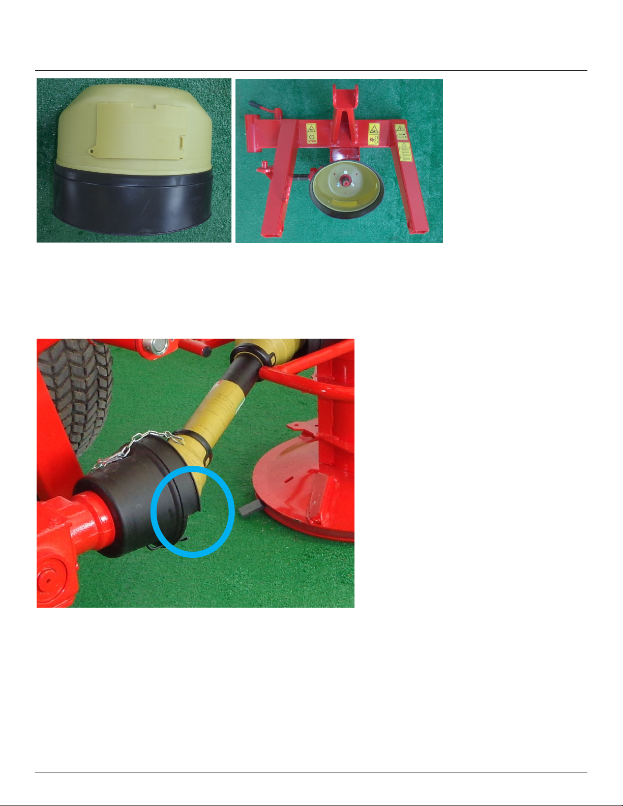
Figure 3 larger guard installed on the gearbox facing the tractor .............................................. 2
Figure 4 smaller guard with cut-out facing the rear (cutout may look different than picture) ... 2
Figure 5 the other small guard installed on the drum unit......................................................... 3
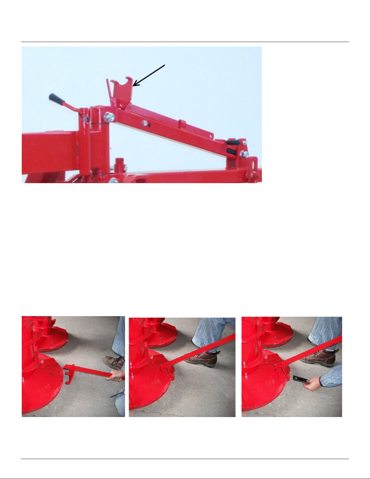
Figure 6 install the pins in the arms as shown............................................................................ 3
Figure 7 3 point hitch attached to tractor’s lift arms.................................................................. 4
Figure 8 plumb the 3 point hitch unit using the top link............................................................. 4
Figure 9 blade tool ..................................................................................................................... 5
Figure 10 installing a blade ........................................................................................................ 5
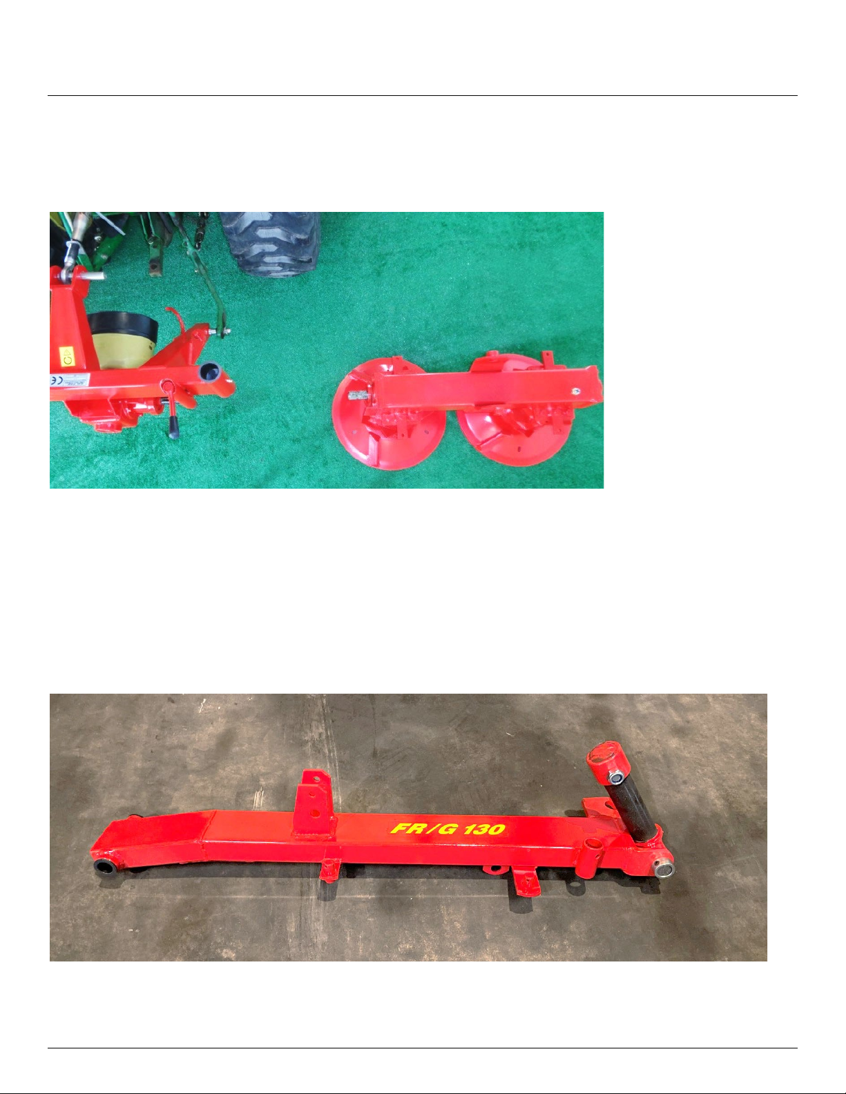
Figure 11 drum unit positioned in relation to the 3-point hitch frame....................................... 6
Figure 12 lift arm and swivel tee in place................................................................................... 6
Figure 13 lower lift arm in place................................................................................................. 7

ASSEMBLY GUIDE
2022-1.1 IBEX EQUIPMENT CO. 2
Figure 14 top spring arm installed with pin blocked up by using a 2x4 ...................................... 7
Figure 15 spring arm attachment to lower arm ......................................................................... 8
Figure 16 push the lower arm down to line up with drum unit.................................................. 8
Figure 17 pivot pin installed....................................................................................................... 9
Figure 18 storage stand ............................................................................................................. 9
Figure 19 transport lock........................................................................................................... 10
Figure 20 shaft with slip clutch end.......................................................................................... 11
Figure 21 connect the driveline with one-way clutch............................................................... 11
Figure 22 guard chains attached .............................................................................................. 12
Figure 23 pivot restrictor plate & handle installation............................................................... 13
Figure 24 pivot restrictor plate & handle shown installed from side....................................... 13
Figure 25 front guard has six holes .......................................................................................... 14
Figure 26 curtain straps secure to the guard frame ................................................................. 14
Figure 27 curtain installed with 2 holes for toe guard facing forward...................................... 15
Figure 28 safety release bar ..................................................................................................... 15

ASSEMBLY GUIDE
2022-1.1 IBEX EQUIPMENT CO. 3
SCOPE AND PURPOSE
This guide is limited to Ibex TS51C drum mowers (also labeled with the original manufacturer
model name, Galfre FR/G 130). The guide covers models manufactured in 2020 and forward.
This manual is a guide to aid in the assembly only. Consult the Quick Start Guide and User
Manual for instructions on usage and safety.
UNCRATING
Heavier components can be lifted out of the crate, using lift straps or chains, if a lift is
available.
Figure 1 lifting the drum assembly
If no lift is available, the crate will need to be cut open for easier access. Remove the smaller
parts, then slide the drum unit out of the crate onto the ground. The drum mower bottom
skids drag across the ground during use, so it is alright to drag them to the location that you
plan to use for assembly. Lay out the parts so you can see everything in one place.
Take the bag of parts and sort them out in like groupings. It makes finding the hardware much
easier during assembly. Refer to Figure 2 and the subsequent list for hardware identification.
Note: Occasionally the manufacturer will pre-install some components and this may result in
your hardware assortment being slightly different than what is shown.

ASSEMBLY GUIDE
2022-1.1 IBEX EQUIPMENT CO. 4
Figure 2 hardware
Hardware Guide
A. Top link pin
B. 3-point hitch pins (Figure 6)
C. Transport lock (Figure 19)
D. Pivot restrictor handle (Figure 23)
E. Pivot restrictor plate (Figure 23)
F. Drum mower blades
G. Spring arm nut/bolt (Figure 15)
H. Stand retention clip (Figure 18)
I. Pivot restrictor handle washers (Figure 23)
J. Curtain frame nuts/bolts (Figure 25)
K. Hardware for large PTO guard (Figure 3)
L. Hardware for small PTO guard (Figure 5)
M. Hardware for transport lock (Figure 19)
N. Hardware for pivot restrictor plate (Figure 23)
O. Roll pins to retain 3 point hitch pins
P. R-clips to secure breakaway bar (Figure 28)
PTO GUARD INSTALLATION
Install the plastic PTO guards. They are easier to install before assembling the mower. Use the
set of 4 screws and washers provided in the hardware bag to install the larger guard on the
gearbox facing the tractor as shown in Figure 3. Note that this guard may appear somewhat
different, and may already be installed on the gearbox.

ASSEMBLY GUIDE
2022-1.1 IBEX EQUIPMENT CO. 2
Figure 3 larger guard installed on the gearbox facing the tractor
The small guard with a cutout is installed on the 90 degree gearbox on the other side, with the
cutout facing the rear. This cutout provides space to allow the PTO shaft to pivot to 90 degrees
when the mower is switched to transport mode. This guard is normally already installed.
Figure 4 smaller guard with cut-out facing the rear (cutout may look different than picture)
Get the small guard without a cutout and use the set of 3 small screws and washers to install it
at the drum unit PTO connection as shown in Figure 5.

ASSEMBLY GUIDE
2022-1.1 IBEX EQUIPMENT CO. 3
Figure 5 the other small guard installed on the drum unit
THREE POINT HITCH
Find the two 3 point hitch pins (Figure 2, B) and the 2 smaller roll pins (Figure 2, O). The hitch
pins can be installed facing outward or inward to accommodate different lift arm widths, so
you may want to bring the hitch close to your tractor to see how it lines up before you decide
which position to install the pins.
Position the 3 point hitch so the two arms face up. Oil the holes in the pins and in the hitch,
and then oil the roll pin. Secure the roll pin with locking pliers and drive it through the holes
with a hammer.
Figure 6 install the pins in the arms as shown

ASSEMBLY GUIDE
2022-1.1 IBEX EQUIPMENT CO. 4
Attach the 3 point hitch to your tractor’s lift arms. You will need linchpins to secure them (not
included).
Figure 7 3 point hitch attached to tractor’s lift arms
Lift the 3 point hitch unit up and install the top link pin (Figure 2, A). Adjust the length of the
top link so that the 3 point hitch is plumb (straight up and down).
Figure 8 plumb the 3 point hitch unit using the top link
BLADE INSTALLATION
The six cutting blades that come with the mower are installed and changed with the blade
change tool. The blade change tool is stored on the top of the spring arm that connects the 3
point hitch to the drum unit, shown in Figure 9 fully assembled for identification.

ASSEMBLY GUIDE
2022-1.1 IBEX EQUIPMENT CO. 5
Figure 9 blade tool
To install a blade, position the blade change tool so that the two identical prongs are inserted
between the two discs of the drum, as seen in Figure 10. Raise the arm so that the pin of the
tool inserts into the slot on the upper disc. Pivot the tool up until there is sufficient clearance,
install the blade, and let the tool arm down. Be sure to install the blade so that its angled
edges are sloped downward. Once installed, be sure the blade is on the pin and swings freely.
Note that the drum unit may need to be raised to provide enough clearance to properly angle
the tool.
For safety purposes, never place your hand or fingers inside the opened space between the
discs.
Figure 10 installing a blade

ASSEMBLY GUIDE
2022-1.1 IBEX EQUIPMENT CO. 6
ATTACHING THE DRUM UNIT TO THE 3 POINT HITCH
Place the drum unit so that it is oriented as shown in Figure 11. Be sure the PTO spline shafts
face each other.
Figure 11 drum unit positioned in relation to the 3-point hitch frame
To connect the 3 point hitch frame to the drum unit, first get the larger lift arm with a swivel
tee attached to it, shown in Figure 12. Remove the cap of the tee and place it on top of the
drum unit with the tee facing the 3 point hitch. Slide the tee into the 3 point hitch frame and
install the cap as shown in Figure 13, threading the nut only until you feel some resistance. The
nut will be removed later when mounting the top arm. Wait to attach the other end of the
lower arm until after the next step.
Figure 12 lower lift arm and swivel tee in place

ASSEMBLY GUIDE
2022-1.1 IBEX EQUIPMENT CO. 7
Figure 13 lower lift arm in place
To install the top arm (“spring arm”), first support the lower arm as shown in Figure 14 with a
2 foot length of 2x4 or a floor jack. Doing this will prevent the pivot pin from falling out of the
sleeve when the cap is removed. Attach the top spring arm around the cap as shown in Figure
14 and secure the nut and bolt. Fully secure the nut this time, but do not over-tighten it as the
pin needs to be able to pivot. The 2x4 / jack is no longer needed at this point.
Figure 14 top spring arm installed with pin blocked up by using a 2x4

ASSEMBLY GUIDE
2022-1.1 IBEX EQUIPMENT CO. 8
Connect the lower arm to the spring arm as shown in Figure 15 using the spring arm nut/bolt
(Figure 2, G). Be sure the bolt goes through the loop on the end of the spring. The lower arm
will need to be raised up at an angle as shown in Figure 15 to line everything up.
Figure 15 spring arm attachment to lower arm
To attach the lower arm to the drum unit, you will need to put downward force on the lift arm.
You will be extending the suspension spring when you do this. If you are working by yourself,
try using a ratchet strap to pull the arm down to make this operation easier.
Figure 16 push the lower arm down to line up with drum unit
The holes must be lined up before attempting to drive the pin through. Use a long screwdriver,
long punch, or a similar tool to line up the holes while attempting to drive the pin. Do not
force the pin through, as you can damage the nylon bushings. A little oil on the pin can help.
Use the top link to adjust the angle and adjust the height of the 3 point hitch to better line up
the holes. Use patience as the pin will not go through easily until it is lined up well. Try nudging
the drum unit to get all holes aligned at the same time.

ASSEMBLY GUIDE
2022-1.1 IBEX EQUIPMENT CO. 9
Install the washer and nut on the pivot pin. The nut is a nylon locking nut and should not be
over-tightened. Insert a screwdriver in the hole in the pin if necessary to prevent it from
turning while securing the nut.
Figure 17 pivot pin installed
STORAGE STAND
Install the storage stand as shown in Figure 18 using the clip provided (Figure 2, H).
Figure 18 storage stand

ASSEMBLY GUIDE
2022-1.1 IBEX EQUIPMENT CO. 10
TRANSPORT LOCK
Install the transport lock for the spring arm as shown in Figure 19 using the nut/bolt found in
the hardware bag (Figure 2, M).
Figure 19 transport lock installed
PTO SHAFTS
Grease the U-joints and the plastic bearings of the PTO shafts before assembly. Your mower
comes with two different PTO shafts, one with a slip clutch and another with a one-way clutch.
It’s important to install them in the correct location, and in the correct direction. Examples of
the two clutches are shown below. Note that the shafts that come with your machine may
appear slightly different or be a different color.
Slip Clutch
One-Way Clutch

ASSEMBLY GUIDE
2022-1.1 IBEX EQUIPMENT CO. 11
The PTO shaft with the slip clutch is attached between the 90 degree gearbox and the tractor,
as shown in Figure 20. The slip clutch (the wider end with the springs) attaches to the mower,
while the other end attaches to the tractor.
Figure 20 shaft with slip clutch end
As with any new implement, the shaft that attaches to the tractor may need to be cut to
length. Consult the included Ibex Equipment PTO Shaft Cutting Guide.
The PTO shaft with the one-way clutch installed between the 90 degree gearbox and the
mower’s drum unit, as oriented in Figure 21. Install the thicker clutch end so that it is attached
to the drum unit.
Figure 21 connect the driveline with one-way clutch

ASSEMBLY GUIDE
2022-1.1 IBEX EQUIPMENT CO. 12
Attach the PTO shaft guard chains as shown in Figure 22 so that the guards do not spin during
operation.
Figure 22 guard chains attached
Read the manuals that are supplied with your PTO shafts before operating the machinery.
Failure to follow all safety procedures in the manufacturer’s literature could lead to equipment
damage, personal injury or death.
As noted before, the PTO shaft that attaches to the tractor is supplied long because the
lengths of lift arms on tractors vary. It is typical to have to shorten the PTO shaft before using
the implement with your tractor. If you have more than one tractor, it is important to cut the
shaft for the tractor you will be using the implement with. Mark the PTO shaft with permanent
marker as to which tractor it is to be used with to avoid confusion that could lead to damage.
Using a PTO shaft that is too short can cause the PTO to separate during use that could lead to
damage or personal injury.
The PTO shaft must never completely collapse during operation. This would compress the
weight of the implement against the tractor and implement’s PTO splines. The output bearings
on the tractor are not designed to accept thrust forces against the PTO.
Consult the included Ibex Equipment PTO Shaft Cutting Guide to learn how to check whether
the shaft must be cut and how to perform this procedure.
PIVOT RESTRICTOR
The drum unit rests completely on the ground during operation, and variation in the terrain
will cause it to move up and down and pivot on the central pin. The pivot restrictor keeps the
mower from pivoting too far and prevents excess movement while in transport mode.
Install the pivot restrictor plate (Figure 2, E) and pivot restrictor handle (Figure 2, D) using the
hardware (Figure 2, N). Use Figures 23 and 24 as a guide. Note that the washers provided to

ASSEMBLY GUIDE
2022-1.1 IBEX EQUIPMENT CO. 13
you may look different than in the picture. Often standard flat washers are provided as
shown in the Hardware Guide on p.4 instead of the odd-shaped washers shown. Install the
washers in whichever configuration places the pivot restrictor plate in a straight vertical
position (plumb).
Figure 23 pivot restrictor plate & handle installation
Figure 24 pivot restrictor plate & handle shown installed from side
The pivot restrictor handle should be tightened during transport only. During mowing, the
handle is loosened so that the mower pivots freely within the range allowed by the slot in the
restrictor plate.

ASSEMBLY GUIDE
2022-1.1 IBEX EQUIPMENT CO. 14
GUARD INSTALLATION
Use the curtain frame nuts & bolts (Figure 2, J) to install the curtain frame as shown in Figure
25. Align the pin of the front frame piece to the hole in the rear frame piece, then bolt both
onto the drum unit. Do not install the optional bumper guard yet (the double-T shaped frame
seen in Figure 27), as the curtain must be fitted first. It’s best to fit all nuts & bolts loosely
before tightening them to allow for adjustment as the holes are not precision-aligned.
Figure 25 front guard has six holes
Secure the curtain around the frame using the included straps as shown in Figure 26.
Figure 26 curtain straps secure to the guard frame

ASSEMBLY GUIDE
2022-1.1 IBEX EQUIPMENT CO. 15
You can now install the optional bumper guard if desired. The bumper guard can help to cut
certain taller crops more efficiently.
Figure 27 curtain installed with 2 holes for toe guard facing forward
SAFETY RELEASE (“BREAKAWAY BAR”)
The safety release bar (also called the “breakaway bar”) is installed in the orientation shown in
Figure 28 when the mower is in mowing position.
Figure 28 safety release bar
The breakaway bar is removed and reinstalled in a different position for transport mode. See
the owner’s manual for more information regarding switching to transport mode.

ASSEMBLY GUIDE
2022-1.1 IBEX EQUIPMENT CO. 16
LUBRICATION
Verify that there is oil in the 90 degree gearbox and drum unit gear chamber, and lubricate all
grease points. Some of the grease points will take more grease than usual the first time they
are lubricated due to filling up the air space between the bushings.
The 90 degree gearbox is filled to the bottom of the fill hole/fill level hole on the side.
The gearbox over the drums should contain about 3 quarts of oil. The oil is not easily visible, so
use a straw or another type of clean stick to check the level when the drum unit is on level
ground. About 1-3/4 to 2 inches of oil is the correct level.
Do not overfill the gearboxes. Having the gearboxes too full of oil will cause overheating,
foaming and premature failure of the lubricating oil.
The correct oil for both the 90 degree gearbox and the drum unit reservoir is a gear oil near 90
weight (80W90 is commonly found in stores) that is rated for EP, or extreme pressure.
Other manuals for TS51C
3
Table of contents
Other IBEX Farm Equipment manuals
Popular Farm Equipment manuals by other brands

AG SPRAY
AG SPRAY LA9000 Operation & maintenance manual

Sulky
Sulky Polyvrac XT 100 VISION Technician's Operating Manual

Farmet
Farmet EXCELENT PREMIUM 6 Instructions for use

Smithco
Smithco V-STAR 94-201 Service manual

Topcon
Topcon OPUS A3 STANDARD Full Technical data sheet

AIRTUG
AIRTUG TT-HD-EM-8 Assembly & operating instructions