G
4 5
FRAME GEOMETRY CHART
Size Small Medium Large X-Large
Seattube A 14.5” 16.5” 18.5” 20.5”
Toptube B 580 mm 600 mm 620 mm 640 mm
Headtube C 85 mm 105 mm 117 mm 132 mm
Chainstay D 430 mm 430 mm 430 mm 430 mm
Seat Angle E 73.6° 72.6° 72.6° 72.6°
Head Angle F 66.6° 66.6° 66.6° 66.6°
Wheelbase G 1135 mm 1146 mm 1168 mm 1189 mm
Stack 580 mm 599 mm 610 mm 624 mm
Reach 411 mm 414 mm 431 mm 446 mm
Size Small Medium Large X-Large
Seattube A 15” 17” 19” 21”
Toptube B 564 mm 584 mm 605 mm 625 mm
Headtube C 78 mm 94 mm 100mm 107 mm
Chainstay D 422 mm 422 mm 422 mm 422 mm
Seat Angle E 73° 73° 73° 73°
Head Angle F 70° 70° 70° 70°
Wheelbase G 1131mm 1142mm 1164mm 1185mm
Stack 599 mm 615 mm 620 mm 627 mm
Reach 379 mm 397 mm 413 mm 432 mm
Mojo HD 3 Ripley 29
• 650b (27.5”) wheels
• 150mm rear wheel dw-link travel
• Approved for 150-160mm forks
• 67º head angle with a 150mm fork ( 66.6º with 160mm fork)
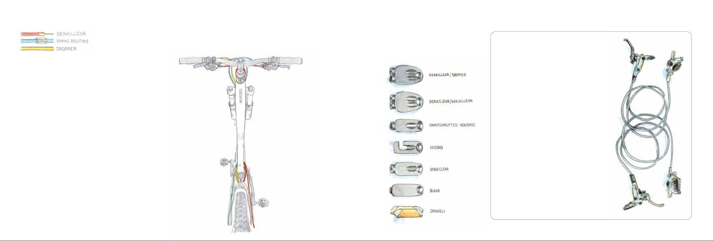
• Super versatile internal cable routing
• Optional polycarbonate down tube cable guard
• Chain stay length: 16.9”
• Threaded bottom bracket (68mm English thread)
• ISCG 05 compatible with removable adapter
• Tapered head tube and steerer, ZS44 upper, ZS56 lower
• 12 x 142mm Maxle rear axle
• 160mm post mount left dropout, carbon ber
• 29” wheels
• 120mm rear wheel dw-link travel
• Approved for 120-140mm forks, 32 or 34 stanchion
• 70º head angle with a 120mm fork (68.5º with 140mm fork)
• Super versatile internal cable routing
• Chain stay length: 17.4”
• BB92/Press GXP style integrated Bottom Bracket
• High direct mount front derailleur on swingarm
• Tapered head tube and steerer: ZS44 upper, EC49 lower
• 12 x 142mm Maxle rear axle
• 160mm post mount left dropout, carbon ber
FRAME GEOMETRY CHART
Size Small Medium Large X-Large
Seattube A 14.5” 17” 19” 21”
Toptube B 564 mm 584 mm 605 mm 625 mm
Headtube C 78 mm 94 mm 100 mm 115 mm
Chainstay D 435 mm 435 mm 435 mm 435 mm
Seat Angle E 73° 73° 73° 73°
Head Angle F 71° 71° 71° 71°
Wheelbase G 1045 mm 1066 mm 1087 mm 1107 mm
Stack 607 mm 622 mm 628.5 mm 642 mm
Reach 378 mm 393 mm 411 mm 437 mm
Size 47 50 53 55 58 61
Seattube A 470 mm 500 mm 530 mm 550 mm 580 mm 610 mm
Toptube B 520 mm 530 mm 540 mm 555 mm 570 mm 590 mm
Headtube C 100 mm 115 mm 135 mm 155 mm 175 mm 195 mm
Chainstay D 430 mm 430 mm 430 mm 430 mm 430 mm 430 mm
Seat Angle E 74.5° 74° 73.5° 73° 73° 73°
Head Angle F 70.5° 71° 71.5° 71.5° 71.5° 71.5°
Wheelbase G 1007 mm 1009 mm 1011 mm 1024 mm 1037 mm 1057 mm
Stack 523 mm 538 mm 559 mm 578 mm 596 mm 616 mm
Reach 373 mm 374 mm 374 mm 377 mm 387 mm 400 mm
Tranny 29 Hakkalügi Disc 700cc
• 29” wheels
• Approved for 120-140mm forks, 32 or 34 stanchion
• 71º head angle with a 100mm fork (70º with 120 fork)
• Super versatile internal cable routing
• Provision for cable-actuated adjustable seat posts
• Chain stay length: 17.1”
• Single speed and belt drive compatible
• BB92/Press GXP style integrated Bottom Bracket
• High direct mount front derailleur
• Tapered head tube and steerer: ZS44 upper, EC49 lower
• 12 x 142mm Maxle rear axle
• 160mm post mount left dropout, carbon ber
• 700c wheels
• Trail: 67mm @ 71.5º head angle, 70mm @ 71º and 73mm @ 70.5º
• Chain stay length: 16.9”
• BB86 Press Fit Bottom Bracket
• 34.9mm top pull front derailleur
• Tapered head tube: IS 41/28.6 upper, IS 52/40 lower
• 135mm rear dropout spacing
• Post mount for rear disc brake 140mm