A
EF
B
G
D
STACK
C
REACH
A
EF
B
G
D
STACK
C
REACH
B
G
D
REACH
STACK
A
EF
C
4 5
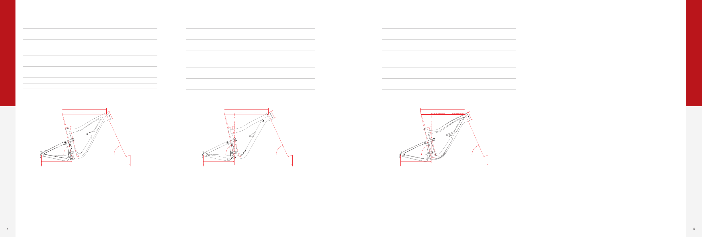
• 29” wheels
• 147mm rear wheel dw-link travel
• Approved for 160mm forks
• 64.9º head angle with a 160mm fork
• Cable routing through continuous internal tubes
• Chainstay length: 17.1”
• Threaded bottom bracket (73mm English thread)
• ISCG 05 compatible with optional removable adapter
• Tapered headtube and steerer: ZS44 upper, ZS56 lower
• 12 x 148mm BOOST rear axle
• 160mm post mount rear brake
• 29” wheels
• 147mm rear wheel dw-link travel
• Approved for 160mm forks
• 64.9º head angle with a 160mm fork
• Super versatile internal cable routing
• Chainstay length: 17.1”
• Threaded bottom bracket (73mm English thread)
• ––– 05 compatible with optional removable adapter
• Tapered headtube and steerer: ZS44 upper, ZS56 lower
• 12 x 148mm BOOST rear axle
• 160mm post mount rear brake
SIZE SMALL MEDIUM LARGE X-LARGE
SEATTUBE A 14.5” 14.5” 16.5 18.5”
TOPTUBE B 573mm 603mm 632mm 655mm
HEADTUBE C 90mm 100mm 110mm 120mm
CHAINSTAY D 435mm 435mm 435mm 435mm
SEAT ANGLE E 77° 76° 76° 76°
HEAD ANGLE F 64.9° 64.9° 64.9° 64.9°
WHEELBASE G 1177mm 1195mm 1220mm 1249mm
STACK 613mm 620mm 629mm 642mm
REACH 431mm 446mm 471mm 493mm
STANDOVER 705mm 750mm 750mm 760mm
BB DROP 29mm 29mm 29mm 29mm
SADDLE HEIGHT FOR
SEATTUBE ANGLE
650mm 700mm 750mm 800mm
SIZE SMALL MEDIUM LARGE X-LARGE
SEATTUBE A 14” 15” 16.5” 18.5”
TOPTUBE B 573mm 603mm 632mm 655mm
HEADTUBE C 90mm 100mm 110mm 120mm
CHAINSTAY D 435mm 435mm 435mm 435mm
SEAT ANGLE E 77° 76° 76° 76°
HEAD ANGLE F 64.9° 64.9° 64.9° 64.9°
WHEELBASE G 1185mm 1216mm 1237mm 1262mm
STACK 613mm 620mm 629mm 642mm
REACH 431mm 458mm 475mm 495mm
STANDOVER 705mm 750mm 750mm 760mm
BB DROP 30mm 30mm 30mm 30mm
SADDLE HEIGHT FOR
SEATTUBE ANGLE
650mm 700mm 750mm 810mm
RIPMO RIPMO AF
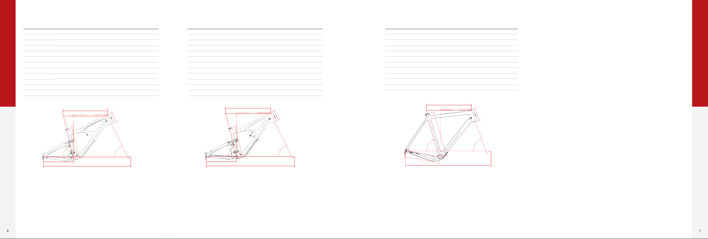
• 29” wheels
• 120mm rear wheel dw-link travel
• Approved for 120-140mm forks
• 66.5º head angle with a 130mm fork
• Cable routing through continuous internal tubes
• Chainstay length: 17”
• Threaded bottom bracket (73mm English thread)
• ISCG 05 compatible with optional removable adapter
• Tapered headtube and steerer: ZS44 upper, ZS56 lower
• 12 x 148mm BOOST rear axle
• 160mm post mount rear brake
SIZE SMALL MEDIUM LARGE X-LARGE
SEATTUBE A 14.5” 15” 16.5” 19”
TOPTUBE B 574mm 603mm 630mm 658mm
HEADTUBE C 90mm 105mm 115mm 125mm
CHAINSTAY D 432mm 432mm 432mm 432mm
SEAT ANGLE E 76° 76° 76° 76°
HEAD ANGLE F 66.5° 66.5° 66.5° 66.5°
WHEELBASE G 1147mm 1178mm 1207mm 1236mm
STACK 599mm 613mm 622mm 631mm
REACH 425mm 450mm 475mm 500mm
STANDOVER 708mm 712mm 742mm 755mm
BB DROP 38mm 38mm 38mm 38mm
SADDLE HEIGHT FOR
SEATTUBE ANGLE
650mm 700mm 750mm 800mm
RIPLEY
BUILD
BUILD