manuals.online logo
Brands
  1. Home
  2. •
  3. Brands
  4. •
  5. IBM
  6. •
  7. Desktop
  8. •
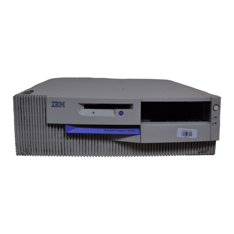
  9. IBM PC 300GL Types 6275 Technical manual

IBM PC 300GL Types 6275 Technical manual

Understanding Your Personal Computer
PC 300GL
Understanding Your Personal Computer
PC 300GL
IBM
First Edition (November 1998)
Note: Before using this information and the product it supports, be sure to read the general
information under Appendix, “Notices and Trademarks” on page 48.
The following paragraph does not apply to the United Kingdom or any country where such
provisions are inconsistent with local law: INTERNATIONAL BUSINESS MACHINES
CORPORATION PROVIDES THIS PUBLICATION “AS IS” WITHOUT WARRANTY OF ANY KIND,
EITHER EXPRESS OR IMPLIED, INCLUDING, BUT NOT LIMITED TO, THE IMPLIED
WARRANTIES OF MERCHANTABILITY OR FITNESS FOR A PARTICULAR PURPOSE. Some states
do not allow disclaimer of express or implied warranties in certain transactions, therefore, this
statement may not apply to you.
This publication could include technical inaccuracies or typographical errors. Changes are periodically
made to the information herein; these changes will be incorporated in new editions of the publication.
IBM may make improvements and/or changes in the product(s) and/or the program(s) described in
this publication at any time.
This publication was developed for products and services offered in the United States of America.
IBM may not offer the products, services, or features discussed in this document in other countries,
and the information is subject to change without notice. Consult your local IBM representative for
information on the products, services, and features available in your area.
Requests for technical information about IBM products should be made to your IBM reseller or IBM
marketing representative.
 Copyright International Business Machines Corporation 1998. All rights reserved.
Note to U.S. Government Users — Documentation related to restricted rights — Use, duplication or
disclosure is subject to restrictions set forth in GSA ADP Schedule Contract with IBM Corp.
Contents
Overview . . . . . . . . . . . . . . . . . . . . . . . . . . . . . . . . . . . . . . . . . . . . . . . . vi
Chapter 1. Microprocessors and Memory ............................ 1
Microprocessors . . . . . . . . . . . . . . . . . . . . . . . . . . . . . . . . . . . . . . . . . . . . 1
Microprocessor Speed . . . . . . . . . . . . . . . . . . . . . . . . . . . . . . . . . . . . . . . 1
Microprocessor Cache . . . . . . . . . . . . . . . . . . . . . . . . . . . . . . . . . . . . . . . 2
Microprocessor Bus . . . . . . . . . . . . . . . . . . . . . . . . . . . . . . . . . . . . . . . . 2
Microprocessor Instructions . . . . . . . . . . . . . . . . . . . . . . . . . . . . . . . . . . . 2
Memory . . . . . . . . . . . . . . . . . . . . . . . . . . . . . . . . . . . . . . . . . . . . . . . . . 2
Main Memory . . . . . . . . . . . . . . . . . . . . . . . . . . . . . . . . . . . . . . . . . . . . 3
CMOS Memory . . . . . . . . . . . . . . . . . . . . . . . . . . . . . . . . . . . . . . . . . . . 3
Flash Memory . . . . . . . . . . . . . . . . . . . . . . . . . . . . . . . . . . . . . . . . . . . . 3
Cache Memory . . . . . . . . . . . . . . . . . . . . . . . . . . . . . . . . . . . . . . . . . . . 4
Memory Organization . . . . . . . . . . . . . . . . . . . . . . . . . . . . . . . . . . . . . . . 5
Physical and Virtual Memory .................................. 6
Control Logic . . . . . . . . . . . . . . . . . . . . . . . . . . . . . . . . . . . . . . . . . . . . . . 7
Chapter 2. Expansion-Bus . . . . . . . . . . . . . . . . . . . . . . . . . . . . . . . . . . . . . 8
PCI-Bus . . . . . . . . . . . . . . . . . . . . . . . . . . . . . . . . . . . . . . . . . . . . . . . . . 8
PCI Interface . . . . . . . . . . . . . . . . . . . . . . . . . . . . . . . . . . . . . . . . . . . . 9
PCI Performance . . . . . . . . . . . . . . . . . . . . . . . . . . . . . . . . . . . . . . . . . . 9
ISA-Bus . . . . . . . . . . . . . . . . . . . . . . . . . . . . . . . . . . . . . . . . . . . . . . . . . 9
Expansion-Bus Slots . . . . . . . . . . . . . . . . . . . . . . . . . . . . . . . . . . . . . . . . . . 10
Adapter Configuration . . . . . . . . . . . . . . . . . . . . . . . . . . . . . . . . . . . . . . . . 10
Plug and Play Adapters ...................................... 10
Legacy Adapters . . . . . . . . . . . . . . . . . . . . . . . . . . . . . . . . . . . . . . . . . . 11
Chapter 3. Video . . . . . . . . . . . . . . . . . . . . . . . . . . . . . . . . . . . . . . . . . . . 12
Monitors . . . . . . . . . . . . . . . . . . . . . . . . . . . . . . . . . . . . . . . . . . . . . . . . . 12
Resolution and Dot Pitch ..................................... 12
Scanning Characteristics . . . . . . . . . . . . . . . . . . . . . . . . . . . . . . . . . . . . . . 12
DDC Protocol . . . . . . . . . . . . . . . . . . . . . . . . . . . . . . . . . . . . . . . . . . . . 13
Power Management . . . . . . . . . . . . . . . . . . . . . . . . . . . . . . . . . . . . . . . . 13
Selecting a Monitor ........................................ 14
Using Monitor Controls ...................................... 14
Using Screen Savers ........................................ 15
Video Control . . . . . . . . . . . . . . . . . . . . . . . . . . . . . . . . . . . . . . . . . . . . . 15
AGP Video Controller ........................................ 15
Video Drivers . . . . . . . . . . . . . . . . . . . . . . . . . . . . . . . . . . . . . . . . . . . . 15
SVGA Mode . . . . . . . . . . . . . . . . . . . . . . . . . . . . . . . . . . . . . . . . . . . . . . 16
Special Characters and Languages ................................. 16
Chapter 4. I/O Features . . . . . . . . . . . . . . . . . . . . . . . . . . . . . . . . . . . . . . . 17
 Copyright IBM Corp. 1998 iii
Audio Ports . . . . . . . . . . . . . . . . . . . . . . . . . . . . . . . . . . . . . . . . . . . . . . . 17
Serial Port . . . . . . . . . . . . . . . . . . . . . . . . . . . . . . . . . . . . . . . . . . . . . . . . 18
Universal Serial Bus Ports ...................................... 19
Parallel Port . . . . . . . . . . . . . . . . . . . . . . . . . . . . . . . . . . . . . . . . . . . . . . 20
Keyboard Port . . . . . . . . . . . . . . . . . . . . . . . . . . . . . . . . . . . . . . . . . . . . . 22
Keyboard Layout . . . . . . . . . . . . . . . . . . . . . . . . . . . . . . . . . . . . . . . . . . 22
Languages . . . . . . . . . . . . . . . . . . . . . . . . . . . . . . . . . . . . . . . . . . . . . . 26
Mouse Port . . . . . . . . . . . . . . . . . . . . . . . . . . . . . . . . . . . . . . . . . . . . . . . 26
Monitor Port . . . . . . . . . . . . . . . . . . . . . . . . . . . . . . . . . . . . . . . . . . . . . . 27
Chapter 5. Storage Devices . . . . . . . . . . . . . . . . . . . . . . . . . . . . . . . . . . . . . 28
Diskette Drives . . . . . . . . . . . . . . . . . . . . . . . . . . . . . . . . . . . . . . . . . . . . . 28
Diskettes . . . . . . . . . . . . . . . . . . . . . . . . . . . . . . . . . . . . . . . . . . . . . . . . 28
Identifying Diskettes . . . . . . . . . . . . . . . . . . . . . . . . . . . . . . . . . . . . . . . . 28
Handling and Storing Diskettes ................................. 30
Labeling Diskettes . . . . . . . . . . . . . . . . . . . . . . . . . . . . . . . . . . . . . . . . . 31
Inserting and Removing Diskettes ................................ 31
Write Protecting Diskettes .................................... 32
Formatting Diskettes . . . . . . . . . . . . . . . . . . . . . . . . . . . . . . . . . . . . . . . . 32
Copying Diskettes . . . . . . . . . . . . . . . . . . . . . . . . . . . . . . . . . . . . . . . . . 33
Hard Disk Drives ........................................... 33
IDE . . . . . . . . . . . . . . . . . . . . . . . . . . . . . . . . . . . . . . . . . . . . . . . . . . 34
SCSI . . . . . . . . . . . . . . . . . . . . . . . . . . . . . . . . . . . . . . . . . . . . . . . . . . 34
CD-ROM Drives . . . . . . . . . . . . . . . . . . . . . . . . . . . . . . . . . . . . . . . . . . . . 34
Zip Drives . . . . . . . . . . . . . . . . . . . . . . . . . . . . . . . . . . . . . . . . . . . . . . . 35
Chapter 6. Security . . . . . . . . . . . . . . . . . . . . . . . . . . . . . . . . . . . . . . . . . . 36
Information Backup . . . . . . . . . . . . . . . . . . . . . . . . . . . . . . . . . . . . . . . . . . 37
Erased Files . . . . . . . . . . . . . . . . . . . . . . . . . . . . . . . . . . . . . . . . . . . . . . . 37
Computer Viruses . . . . . . . . . . . . . . . . . . . . . . . . . . . . . . . . . . . . . . . . . . . 37
Chapter 7. Software . . . . . . . . . . . . . . . . . . . . . . . . . . . . . . . . . . . . . . . . . 39
Software Layers . . . . . . . . . . . . . . . . . . . . . . . . . . . . . . . . . . . . . . . . . . . . 39
POST . . . . . . . . . . . . . . . . . . . . . . . . . . . . . . . . . . . . . . . . . . . . . . . . . . . 40
Configuration/Setup Utility Program ............................... 40
Operating Systems . . . . . . . . . . . . . . . . . . . . . . . . . . . . . . . . . . . . . . . . . . 41
Device Drivers . . . . . . . . . . . . . . . . . . . . . . . . . . . . . . . . . . . . . . . . . . . . . 41
Latest Level Device Drivers ................................... 41
Device-Driver Types . . . . . . . . . . . . . . . . . . . . . . . . . . . . . . . . . . . . . . . . 42
Video Device Drivers ....................................... 42
Advanced Power Management ................................... 42
Advanced Configuration Power Interface (ACPI) ........................ 43
Application Programs . . . . . . . . . . . . . . . . . . . . . . . . . . . . . . . . . . . . . . . . . 43
Protecting Your Software ....................................... 43
Chapter 8. Networking and System Management Features ................. 45
Desktop Management Interface (DMI) ............................... 45
iv
Remote Administration . . . . . . . . . . . . . . . . . . . . . . . . . . . . . . . . . . . . . . . . 46
DHCP and RPL ............................................ 46
Wake on LAN ............................................. 46
Wake on Modem ........................................... 47
Wake on Ring ............................................. 47
Appendix. Notices and Trademarks ............................... 48
Notices . . . . . . . . . . . . . . . . . . . . . . . . . . . . . . . . . . . . . . . . . . . . . . . . . 48
Trademarks . . . . . . . . . . . . . . . . . . . . . . . . . . . . . . . . . . . . . . . . . . . . . . . 48
Glossary . . . . . . . . . . . . . . . . . . . . . . . . . . . . . . . . . . . . . . . . . . . . . . . . . 50
v
Overview
This book provides information about microprocessors, memory, bus architectures,
input/output features, video, power management, ports, storage devices, security features,
and software. Not all features and capabilities described in this book are available on all
models.
For specific information on features of the PC 300GL and instructions on how to set up,
operate, install options, program, or maintain your computer, refer to the PC 300GL User
Guide that comes with your computer.
vi  Copyright IBM Corp. 1998
Chapter 1. Microprocessors and Memory
The microprocessor-and-memory subsystem consists of components on the system board
that perform logical operations and calculations, control memory, and manage data-transfer
operations.
The devices and features that make up the microprocessor-and-memory subsystem are:
Microprocessors and buses
Memory and control logic
Microprocessors
The microprocessor controls most of the activity in your computer. Almost all information
passes through it, whether it is a keyboard stroke, data from a disk drive, or information
from a communication network. The microprocessor reads, changes, processes, and reroutes
information as needed.
Your computer comes with an Intel microprocessor that has a 64-bit internal data path
and integrated L2 cache. In addition, the microprocessor incorporates Intel MMX
technology. MMX technology boosts the performance of the microprocessor in processing
graphic, video, and audio data, thereby enhancing the performance of multimedia and
communications software. For information about the type and speed of the microprocessor
in your computer, view the System Summary screen displayed by the Configuration/Setup
Utility Program.
Another key feature of the microprocessor is that it includes system management mode
(SMM), which enables the microprocessor to control power used by peripheral devices and
other components. This makes processing more energy efficient and allows the system to
run cooler.
Microprocessor Speed
The microprocessor operating speed is referred to as clock speed and is measured in
megahertz (MHz)1. The design of the microprocessor determines the maximum clock speed
at which it can operate. A quartz crystal on the system board generates a pulse to the
microprocessor, causing the microprocessor to operate at a specific speed. A clock cycle is
the time that the microprocessor takes to perform instructions at a given clock speed. Clock
cycles are measured in nanoseconds (ns).
1MHz only denotes internal clock speed of the microprocessor, not application performance; many factors affect application
performance.
 Copyright IBM Corp. 1998 1
Microprocessors can operate at two clock speeds: an internal speed for operations within the
microprocessor and an external speed for transferring data in and out of the microprocessor.
Microprocessor Cache
Both level-1 (L1) cache and level-2 (L2) cache are integrated with the microprocessor on the
system board. Cache is high-speed memory that stores information most often used by the
microprocessor. Integrated cache provides a performance increase over the external
placement of cache on the system board. Refer to “Cache Memory” on page 4 for more
information about cache memory.
Microprocessor Bus
The microprocessor has an external bus that connects it with main memory and control
circuits. This pathway, which is also called the processor bus or local bus, has the same bus
width as the microprocessor and operates at the same external speed.
Another computer bus, called the I/O bus or expansion bus, carries data and instructions
between the microprocessor bus and the computer peripherals. The width of the I/O bus is
32 bits. With advanced bus technologies, the speed of the I/O bus might approach that of
the microprocessor bus. With standard bus technology, however, the speed of the I/O bus
is much slower than that of the microprocessor bus. Refer to Chapter 2, “Expansion-Bus”
on page 8 for additional information.
Microprocessor Instructions
Data and instructions are necessary for each processing operation that the microprocessor
performs. Data and instructions are copied from memory into registers within the
microprocessor. Registers are also used to store the data that results from each processing
operation until the data is returned to memory.
The set of instructions that the microprocessor can perform determines whether the
computer can run a particular program. For example, programs written for 32-bit
computers require a microprocessor capable of performing 32-bit instructions.
Memory
Your computer uses several types of memory to store information. This section explains
memory concepts, types of memory, and how the types of memory are used.
Although a computer is a complex machine, the method it uses to store information is quite
simple. All information (data and instructions) is stored in a coded format made up of 0’s
and 1’s. Memory is a series of switches, with an open switch representing a 0 and a closed
switch representing a 1. Each switch represents the smallest unit of computer storage, a bit;
eight consecutive bits of storage equals a byte. Memory is allocated in kilobytes (KB),
megabytes (MB), and gigabytes where 1 KB equals approximately 1000 bytes, 1 MB equals
approximately 1 000 000 bytes, and 1 GB equals approximately 1 000 000 000 bytes. In 1 MB
2Microprocessors and Memory
of memory, the computer can store over 1000000 characters of information. The computer
organizes its memory by assigning an address to each byte as a point of reference. The first
address is 0, and the addresses increase sequentially. When information is written to
memory, the encoded character is placed at a specific address.
Main Memory
Main memory (or system memory) is a temporary workspace that is active only while your
computer is on. Any information placed in main memory is lost when you turn off your
computer. Therefore, if you create or modify information, you must save the data to
permanent storage, such as a diskette or hard disk.
The main memory in your computer uses synchronous dynamic random access memory
(SDRAM) modules for temporary storage of data and instructions. These SDRAM modules
are also known as dual inline memory modules (DIMMs). SDRAM is volatile memory, which
means that it must be constantly refreshed by an electric current. While the computer is
turned off, no current is supplied to the DIMMs, so no data is retained in SDRAM.
The DIMM connectors are located on the system board. For information about the type and
amount of main memory (or System Memory) in your computer, view the System Summary
screen displayed by the Configuration/Setup Utility Program.
CMOS Memory
Your computer also uses some nonvolatile RAM (NVRAM), also called complementary
metal-oxide semiconductor (CMOS) memory, for storing configuration and setup information.
Powered by a small battery, CMOS retains its contents while your computer power is off.
CMOS maintains information about:
Date and time
Security features
Power-management settings
Storage devices
Keyboard and mouse
ISA legacy configuration information
Plug and Play configuration information
Port assignments
I/O addresses and interrupts
Other selectable features
Flash Memory
To store programs for startup procedures and other internal operations, some computers
use read-only memory (ROM). These programs are encoded in ROM modules on the system
board. ROM is nonvolatile memory, which means that it retains its contents when the
computer is turned off. Generally, the contents of a ROM module cannot be modified.
However, electrically erasable programmable ROM (EEPROM) modules (also referred to as flash
memory) can be reprogrammed while they are in the computer.
Microprocessors and Memory 3
Your computer stores various system programs and data in flash memory so that they can be
updated whenever enhancements are made. Stored in flash memory are:
Basic input/output system (BIOS)
Power-on self-test (POST)
Configuration/Setup Utility program
Vital product data (VPD)
Processor update code
Cache Memory
Microprocessors can be so fast that main memory cannot respond to read and write requests
as quickly as the microprocessor can send them. In some cases, main memory imposes one
or more wait states on the microprocessor when it reads data from or writes data to
memory.
A wait state is a period of time (one microprocessor clock cycle) during which the
microprocessor suspends processing and waits for memory to respond to a read or write
operation (a memory I/O operation). The speed of a memory I/O operation is measured in
microprocessor clock cycles, so the microprocessor clock speed determines the minimum
time required for a memory I/O operation. Wait states cause the computer to operate less
efficiently than if the microprocessor were able to continue processing data during memory
I/O operations.
A method of reducing the need for wait states is by using cache memory, which improves
system performance by temporarily storing frequently used data and instructions in a cache.
A cache is a buffer between the microprocessor and main memory.
For information about the cache memory in your computer, view the System Summary
screen displayed by the Configuration/Setup Utility Program.
Level-1 Cache
Level-1 (L1) cache is determined by the type of microprocessor installed in your computer.
The L1 cache for the Intel microprocessors contain high-speed memory, known as static
random access memory (SRAM), that can respond to memory I/O operations without
imposing wait states on the microprocessor.
L1 cache memory is used to store the information most often used by the microprocessor.
This allows a microprocessor to handle information faster than if it had to use the system
memory each time it needed new information. During processing, the cache controller
copies other data and instructions into the cache, replacing data and instructions that are no
longer needed.
Performance is improved each time the microprocessor finds what it needs in the cache (a
cache hit). If it does not find what it needs (a cache miss), the cache controller must locate the
data or instruction in memory and copy it into the cache, while one or more wait states are
4Microprocessors and Memory
imposed on the microprocessor. The cache controller manages the use of the cache so that
the number of cache hits far exceeds the number of cache misses.
Level-2 Cache
Your computer has level-2 (L2) cache memory integrated into the microprocessor. L2 cache
complements L1 cache to increase the probability of cache hits. If the microprocessor cannot
find what it needs in L1 cache, it searches L2 cache. If the data or instruction is not in
either cache, the cache controller locates it in main memory and copies it into both caches.
Cache Mode
The microprocessor frequently updates cache memory with changed data. Caches, in turn,
pass these changes to main memory.
When updating cache memory, your computer uses the write-back mode. In write-back
mode, the microprocessor updates the cache, then goes on to perform other functions while
the cache controller updates main memory.
Write-back mode provides better performance than write-through mode, which is a type of
cache architecture used in some other computers. In write-through mode, a microprocessor
updates main memory directly. Write-through mode is slower because the microprocessor
interacts directly with main memory, which is slower than cache memory.
Memory Organization
Operating systems are responsible for allocating memory space, assigning addresses, and
performing many other tasks associated with memory management.
DOS Memory Management
DOS organizes memory into the following types:
Conventional
Extended
Expanded
Conventional memory is the first 1 MB of memory-address space. Of this, the first 640 KB is
available for use by DOS and application programs. Memory from 640 KB through 1 MB is
reserved as a work space for hardware devices and the BIOS.
Extended memory starts above the first 1 MB, appended to conventional memory. Use of
this space is dependent on the operating system and application programs. Not all
programs can use extended memory.
Expanded memory is controlled through an expanded memory specification (EMS) device
driver, such as the one provided with DOS. The EMS device driver is commonly known as
a memory manager. The EMS device driver uses part of the reserved area of conventional
memory as a work space, and the memory above the first 1 MB as a storage area. The
Microprocessors and Memory 5
memory above the first 1 MB is not written to or read from directly. It is broken into 16 KB
pieces called pages, or 64 KB pieces called frames, and is moved in and out of the reserved
area as needed. When a page or frame is moved into the reserved area, it can be read from
and written to as any other address in conventional memory.
Other Types of Memory Management
Operating systems such as Microsoft Windows 95, Windows 98, and Windows NT have
very sophisticated memory-management systems. These operating systems use a technique
called disk swapping or disk paging. If your computer does not have enough memory to meet
the needs of your active programs, these operating systems transfer the least-used
information from memory to the hard disk to make more memory available. When the
information on the hard disk is needed, it is exchanged with other information in memory.
Microsoft Windows 95, Windows 98, and Windows NT also use memory in another way.
These operating systems assign blocks of memory as virtual DOS machines (VDM). Each
VDM runs independently of the others, providing the same function as a separate computer
running DOS. With very few exceptions, these operating systems are fully compatible with
application programs written for DOS.
If you are using any of these operating systems, adding memory can increase the overall
performance.
Physical and Virtual Memory
Physical memory consists of all the addressable memory locations in the computer. Physical
memory is used to store such items as the operating system, video data, and instructions
and data the computer uses to run programs.
Virtual memory is memory that appears to be allocated to application programs. The
operating system uses a portion of the hard disk as virtual memory, swapping data and
instructions between the hard disk and physical memory.
Virtual memory makes multitasking possible. In a multitasking session, the memory
requirements of all the programs that might be running in the system at the same time can
far exceed the amount of physical memory that is available. The operating system allocates
virtual memory to meet the total memory requirements of each program and then manages
the available physical memory to meet the actual requirements. Thus, the amount of virtual
memory that is allocated can be much greater than the amount of physical memory installed
in the computer.
6Microprocessors and Memory
Control Logic
The control logic consists of the modules on the system board that control access to main
and cache memory by the microprocessor and I/O devices. Control logic includes the
following devices and functions:
Audio-port controller and interface (some models only)
Bus-mastering IDE interface
Counters and timers
Direct memory access (DMA) controller
Diskette-port controller and interface
Interrupt controller
Keyboard and mouse port controller and interface
Memory (DRAM) controller
Microprocessor-interface control
Parallel-port controller and interface
PCI-bus interface
PCI-to-ISA interface
Power-management controller
Serial-port controller and interface
USB-port controller and interface
Microprocessors and Memory 7
Chapter 2. Expansion-Bus
This section gives an overview of the expansion-bus and explains how advanced buses can
improve performance.
A computer bus is a pathway of wires and signals that carries (or transfers) information
inside the computer; information includes data, addresses, instructions, and controls. The
microprocessor has an external bus, called the processor bus or local bus, that carries
information between the microprocessor and main memory. The processor bus has the
same bus width (64 bits) as the microprocessor and operates at the same external speed.
Another computer bus, the expansion-bus, carries information between the microprocessor or
memory and peripheral I/O devices. While processor-bus performance has improved
rapidly, improvements in expansion-bus performance have not equalled those of
microprocessors and some peripheral devices, such as video and disk controllers.
Regardless of how fast the microprocessor and other components are, data transfers
between them must pass through the expansion-bus.
Your computer has two expansion-buses: the ISA-bus and the PCI-bus. PCI is an advanced
expansion-bus standard developed by the computer industry to keep up with performance
improvements of processor buses and advanced peripheral devices. Although advanced
designs can match the performance of the microprocessor bus only up to a point, they do
achieve higher throughput by speeding up the expansion-bus and widening its data path.
PCI is intended to add to the capability provided by the ISA-bus.
PCI-Bus
An answer to the need for a higher-performance expansion-bus is the peripheral component
interconnect (PCI) bus. PCI architecture offers many features that improve expansion-bus
performance such as:
Microprocessor independence
Industry-standard compatibility
Wider data path (32 bits)
Faster data-transfer rates
More efficient data-transfer methods
Enhanced peripheral-device performance
Automatic configuration
8  Copyright IBM Corp. 1998
PCI Interface
The PCI-bus connects to the microprocessor bus through a buffered bridge controller. A
bridge translates signals from one bus architecture to another. PCI and ISA devices get all
their data and control information through the PCI controller. The PCI controller looks at
all signals from the microprocessor bus and then passes them to the ISA controller or to
peripheral devices connected to the PCI-bus. However, the PCI-bus is not governed by the
speed of the microprocessor bus. PCI can operate at speeds as fast as 33 MHz1, slow down,
or even stop if there is no activity on the bus, all independent of the microprocessor’s
operations. Microprocessor independence also makes PCI adaptable to various
microprocessor speeds and families and allows consistency in the design and use of PCI
peripheral devices across multiple computer families.
PCI Performance
One of the most significant features of PCI is its 32-bit data path, which is twice the width
of the ISA data path. With a 32-bit data path, the PCI-bus can transfer more information
per second than the ISA-bus, with its 16-bit data path. Also, PCI operates at higher speeds
of up to 33 MHz. Depending on the mode of operation and computer components used,
the PCI-bus can transfer data at speeds up to 132 MB per second. While many factors can
reduce practical performance, achieving just half or a third of the PCI maximum theoretical
throughput far exceeds the practical performance of the ISA-bus, which operates at 4 MB to
8 MB per second.
ISA-Bus
One of the most widely used and successful expansion-buses is the industry standard
architecture (ISA) bus, also called the AT bus. The ISA-bus is a 16-bit bus that operates at a
speed of 8 MHz. It can transfer up to 8 MB of data per second between the microprocessor
and an I/O device. Practical performance ranges between 4 MB and 8 MB per second.
The ISA-bus continues to be popular because so many adapters, devices, and applications
have been designed and marketed for it. Peripheral devices that do not require faster
throughput, such as fax modems, can use ISA. Also, ISA is adequate for users of DOS
applications in a stand-alone environment, or for DOS network requesters with moderate
performance requirements.
Although the ISA-bus is widely used and is suitable for many applications, it cannot
transfer data fast enough for today's high-speed microprocessors and I/O devices. For
example, the ISA-bus might not provide the performance needed by video devices and
applications with high resolution and high-color content. Also, ISA might not be capable of
handling the throughput required by some fast hard disk drives, network controllers, or
full-motion graphics controllers.
Expansion-Bus 9
Expansion-Bus Slots
If you want to add new capabilities to your computer, you can do so by installing optional
adapters. Your computer provides an ISA-bus expansion slot so you can take advantage of
the wide availability of ISA peripheral devices and applications. Also, PCI-bus expansion
slots allow you to connect high-performance devices to your computer, such as graphics,
SCSI, or LAN adapters.
There are four expansion slots in your computer. Three are dedicated PCI slots and one is a
dedicated ISA slot. These slots are grouped together on the system board.
The width of the expansion-bus determines the type of adapters the computer supports.
The dedicated ISA slots accept only 8-bit or 16-bit ISA adapters, and the dedicated PCI slots
accept only 32-bit PCI adapters. The width of the bus does not affect software
compatibility.
Adapter Configuration
When adding adapters, you might need to manually set a variety of switches on the
adapters. These switches control the assignment of computer resources such as interrupt
request (IRQ) lines, direct memory access (DMA) channels, and memory address ranges.
Determining how to set switches for (or configuring) these resources can be complex. A
better method of configuring adapters and devices called Plug and Play is used on your
computer to make expansion an easier task.
Plug and Play Adapters
Plug and Play is a configuration method that makes expanding your computer easier. Plug
and Play adapters are easier to set up because they are auto-configuring. A Plug and Play
adapter comes with built-in identification and configuration specifications set in memory on
the adapter to provide installation information to the computer during startup. This
information is interpreted by the computer's basic input/output system (BIOS), which supports
Plug and Play. The BIOS routines automatically configure the adapter as long as the
required resources are not already in use.
Adapters designed for PCI slots are Plug and Play devices. Many adapters designed for
ISA slots are not Plug and Play devices. If the adapter you are installing is not Plug and
Play, you must configure it manually.
10 Expansion-Bus
Legacy Adapters
Adapters that are not Plug and Play devices are referred to as legacy devices. The
Configuration/Setup Utility Program can help you manually configure legacy adapters.
The screens of the Configuration/Setup Utility Program show the resources typically
required by adapters:
Memory resources
I/O port resources
Direct memory access (DMA) resources
Interrupt resources
From these screens you can select available resources for the adapter you are installing.
Resources not currently being used by adapters already installed in your computer are set
to Available. When you install an additional legacy adapter, set the resources used to ISA
Resource. This enables the Plug and Play software to configure around legacy adapters,
then you can make the appropriate jumper or switch settings on the adapter. Also, if you
remove an ISA legacy adapter, set the resources it used back to Available. This frees up
those resources for future configurations. Refer to the adapter documentation for
information about required resources. Also, the refer to PC 300GL User Guide for more
information about using the Configuration/Setup Utility Program.
Expansion-Bus 11
Chapter 3. Video
This section describes the video features of your computer, including monitors, the graphics
controller, video modes, and other video features.
Monitors
Although there are various types of monitors, the most common distinguishing
characteristics are resolution, dot pitch, scanning rates, screen size, and color.
Resolution and Dot Pitch
The entire image on a monitor screen is made up of many tiny dots. These dots are called
picture elements or pels. The monitor resolution is described by the number of pels that fill
the screen in an array of horizontal rows and vertical columns. For example, the pels might
be arranged in a horizontal-by-vertical array of 640 x 480 pels to make up a typical screen
image. Higher resolutions, such as 800 x 600 or 1024 x 768 pels, mean more dots on the
screen. The benefit of higher resolutions is either displaying more information at one time
or displaying the same information with a sharper image.
Dot pitch refers to the space between the individual dots or pels. The inside of the monitor
screen is coated with light-emitting materials called phosphors. Color monitors use three
phosphors: red, green, and blue. The phosphor coating consists of dots arranged in a
red-green-blue pattern. The distance from the center of one phosphor dot to the center of
the next phosphor dot of the same color is the dot pitch. Dot pitch is measured in
millimeters, such as 0.28, 0.31, 0.39, and 0.41. In general, the monitor with the highest
resolution and finest dot pitch produces the sharpest image. A monitor with a fine dot
pitch, such as 0.28, produces sharper, better defined characters than a similar monitor that
uses a coarser dot pitch, such as 0.41.
Monitor characteristics can be very important. A computer used extensively for detailed
graphics might need a monitor that shows more colors, at a higher resolution and finer dot
pitch, than one used exclusively for word processing. For some applications, a
black-and-white (monochrome) monitor might work as well or better than a color monitor.
Scanning Characteristics
The phosphors on the inside of the monitor screen hold their brightness and color for a very
short time. Therefore, the image has to be scanned (redrawn) many times each second to
refresh the phosphors. The vertical refresh rate is the speed at which the image on the screen
is redrawn (or scanned). Refresh rates are specified in hertz (Hz).
The image is redrawn from top to bottom (or vertically). By the time the bottom pel rows
are drawn, the top rows are starting to fade. There are two ways of redrawing the image:
interlaced scanning and noninterlaced scanning. The interlaced method draws every other
12  Copyright IBM Corp. 1998

Other manuals for PC 300GL Types 6275

25

This manual suits for next models

1

Other IBM Desktop manuals

IBM NetVista A30 User manual

IBM

IBM NetVista A30 User manual

IBM 686536U - IntelliStation Z - Pro 6865 User manual

IBM

IBM 686536U - IntelliStation Z - Pro 6865 User manual

IBM 3270 User manual

IBM

IBM 3270 User manual

IBM NetVista A22p Instructions for use

IBM

IBM NetVista A22p Instructions for use

IBM ThinkCentre 8127 Owner's manual

IBM

IBM ThinkCentre 8127 Owner's manual

IBM PS/2 CL57 SX Owner's manual

IBM

IBM PS/2 CL57 SX Owner's manual

IBM 5100 Use and care manual

IBM

IBM 5100 Use and care manual

IBM IntelliStation M Pro 6233 Owner's manual

IBM

IBM IntelliStation M Pro 6233 Owner's manual

IBM NetVista A20 User manual

IBM

IBM NetVista A20 User manual

IBM NetWista A60 Type 6838 User manual

IBM

IBM NetWista A60 Type 6838 User manual

IBM DISA e-collaboration User manual

IBM

IBM DISA e-collaboration User manual

IBM ThinkCentre 9212 User manual

IBM

IBM ThinkCentre 9212 User manual

IBM PC 300 User manual

IBM

IBM PC 300 User manual

IBM NetVista S42 User manual

IBM

IBM NetVista S42 User manual

IBM NetVista X40 User manual

IBM

IBM NetVista X40 User manual

IBM PC 300 Manual

IBM

IBM PC 300 Manual

IBM NetVista A22p Quick start guide

IBM

IBM NetVista A22p Quick start guide

IBM IntelliStation A Pro User manual

IBM

IBM IntelliStation A Pro User manual

IBM NetVista A21 Quick start guide

IBM

IBM NetVista A21 Quick start guide

IBM NetVista A21 User manual

IBM

IBM NetVista A21 User manual

IBM 2790 User manual

IBM

IBM 2790 User manual

IBM PC 300 User manual

IBM

IBM PC 300 User manual

IBM 2179 User manual

IBM

IBM 2179 User manual

IBM 6643 User manual

IBM

IBM 6643 User manual

Popular Desktop manuals by other brands

iDOT M2 System User handbook

iDOT

iDOT M2 System User handbook

IC nexus SBC21 Series quick start guide

IC nexus

IC nexus SBC21 Series quick start guide

Lenovo J100 Notice

Lenovo

Lenovo J100 Notice

Intergraph ExtremeZ SAN Start guide

Intergraph

Intergraph ExtremeZ SAN Start guide

ACT apricot Technical reference manual

ACT

ACT apricot Technical reference manual

Flex Giraffenmobil GM 320 Original operating instructions

Flex

Flex Giraffenmobil GM 320 Original operating instructions

Advantech IPC-690 user manual

Advantech

Advantech IPC-690 user manual

JMI Telescopes MAX Computer Operator's guide

JMI Telescopes

JMI Telescopes MAX Computer Operator's guide

Lenovo ThinkCentre M75e Podręcznik użytkownika

Lenovo

Lenovo ThinkCentre M75e Podręcznik użytkownika

Lenovo 07ADA05 user guide

Lenovo

Lenovo 07ADA05 user guide

Asus BM6330 user manual

Asus

Asus BM6330 user manual

IEI Technology UPC-V312-D525 user manual

IEI Technology

IEI Technology UPC-V312-D525 user manual

HP Media Center m200 - Desktop PC manual

HP

HP Media Center m200 - Desktop PC manual

Fujitsu Esprimo D5210 user manual

Fujitsu

Fujitsu Esprimo D5210 user manual

Panasonic Toughpad FZ-M1CCAAXBM operating instructions

Panasonic

Panasonic Toughpad FZ-M1CCAAXBM operating instructions

Lenovo ThinkStation E30 Podręcznik użytkownika

Lenovo

Lenovo ThinkStation E30 Podręcznik użytkownika

Sony PCV-W30 VAIO User Guide  (primary manual) quick start guide

Sony

Sony PCV-W30 VAIO User Guide (primary manual) quick start guide

Lenovo IdeaCentre 310S-08IGM user guide

Lenovo

Lenovo IdeaCentre 310S-08IGM user guide

manuals.online logo
manuals.online logoBrands
  • About & Mission
  • Contact us
  • Privacy Policy
  • Terms and Conditions

Copyright 2025 Manuals.Online. All Rights Reserved.