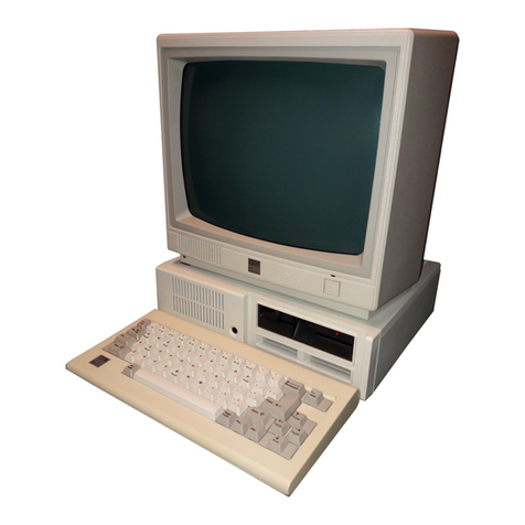
IBM PC/2 25 Owner's manual

FRONT
PICTURE 1
March 21, 1990
Part Number 64F3985
Form Number S64F-3985-00
HMR Diagnostics for Non Micro Channel
¦ Copyright IBM Corp. 1990
FRONT - 1

FRONT_1 Safety Information
Refer to the Hardware Maintenance Reference General Information pamphlet
for the following information:
General Safety
Electrical Safety.
First Edition (March 1990)
The following paragraph does not apply to the United Kingdom or any
country where such provisions are inconsistent with local law:
INTERNATIONAL BUSINESS MACHINES CORPORATION PROVIDES THIS PUBLICATION "AS
IS" WITHOUT WARRANTY OF ANY KIND, EITHER EXPRESS OR IMPLIED, INCLUDING,
BUT NOT LIMITED TO, THE IMPLIED WARRANTIES OF MERCHANTABILITY OR FITNESS
FOR A PARTICULAR PURPOSE. Some states do not allow disclaimer of express
or implied warranties in certain transactions, therefore, this statement
may not apply to you.
This publication could include technical inaccuracies or typographical
errors. Changes are periodically made to the information herein; these
changes will be incorporated in new editions of the publication. IBM may
make improvements and/or changes in the product(s) and/or the program(s)
described in this publication at any time.
It is possible that this publication may contain reference to, or
information about, IBM products (machines and programs), programming, or
services that are not announced in your country. Such references or
information must not be construed to mean that IBM intends to announce
such IBM products, programming, or services in your country.
Requests for technical information about IBM products should be made to
your IBM Authorized Dealer or your IBM Marketing Representative.
IBM may have patents or pending patent applications covering subject
matter in this document. The furnishing of this document does not give
you any license to these patents. You can send license inquiries, in
writing, to the IBM Director of Commercial Relations, IBM Corporation,
Armonk NY 10504.
¦ Copyright International Business Machines Corporation 1990. All rights
reserved.
Note to US Government users-Documentation related to Restricted
rights-Use, duplication, or disclosure is subject to restrictions set
forth in GSA ADP Schedule Contract with IBM Corp.
HMR Diagnostics for Non Micro Channel
Safety Information
¦ Copyright IBM Corp. 1990
FRONT_1 - 1
FRONT_2 Special Notices
References in this publication to IBM products, programs, or services do
not imply that IBM intends to make these available in all countries in
which IBM operates. Any reference to an IBM product, program or service
is not intended to state or imply that only IBM's product, program, or
service may be used. Any functionally equivalent product, program, or
service that does not infringe any of IBM's intellectual property rights
or other legally protectible rights may be used instead of the IBM
product, program, or service. Evaluation and verification of operation in
conjunction with other products, programs, or services, except those
expressly designated by IBM, are the user's responsibility.
IBM may have patents or pending patent applications covering subject
matter in this document. The furnishing of this document does not give
you any license to these patents. You can send license inquiries, in
writing, to the IBM Director of Commercial Relations, IBM Corporation,
Purchase, NY 10577.
The following terms, denoted by an asterisk (*) in this publication, are
trademarks of the IBM Corporation in the United States and/or other
countries:
IBM
Personal System/2
Micro Channel.
HMR Diagnostics for Non Micro Channel
Special Notices
¦ Copyright IBM Corp. 1990
FRONT_2 - 1

CONTENTS Table of Contents
FRONT_1 Safety Information
FRONT_2 Special Notices
CONTENTS Table of Contents
1.0 Introduction to Diagnostics
2.0 Diagnostic Aids
3.0 Power-On Self-Test (POST)
4.0 Icons
4.1 Set Time and Date
4.2 Press F1 to Continue
4.3 Insert a Diskette
4.4 Non-loadable Diskette
4.5 Power-On Password
5.0 Advanced Diagnostics Diskette
5.1 Special Keys
5.2 Diagnostic Menus
5.2.1 Diskette Diagnostic
5.2.2 Fixed Disk Diagnostic
5.2.3 Video Graphics Array
5.2.4 Video Test
5.3 Utilities
5.3.1 Select an Option Menu
5.3.2 Formatting a Fixed Disk Drive
5.3.3 Format Selection Menu
5.3.4 Error Log
5.4 Setup Program
5.4.1 Set Configuration Menu
6.0 Hardware Maintenance Service Pamphlets
7.0 Display Self-Test
HMR Diagnostics for Non Micro Channel
Table of Contents
¦ Copyright IBM Corp. 1990
CONTENTS - 1

1.0 Introduction to Diagnostics
This pamphlet provides diagnostic information for IBM (*) Personal
System/2 (*) non-Micro Channel computers (for example Models 25 and 30).
For diagnostic information about Micro Channel (*) computers (for example,
Models 50, 60, 70, and 80), refer to the Diagnostic Information for Micro
Channel Computers pamphlet.
HMR Diagnostics for Non Micro Channel
Introduction to Diagnostics
¦ Copyright IBM Corp. 1990
1.0 - 1

2.0 Diagnostic Aids
This section provides an introduction to the diagnostic service aids and
how they work together to solve problems. It will serve as a useful
reference until you become familiar with the diagnostic aids.
The diagnostic aids in isolating a failing field replaceable unit (FRU)
are:
Power-On Self-Test (POST)
Advanced Diagnostic Tests on the Advanced Diagnostics Diskette
Hardware Maintenance Service pamphlets.
The display screen drawings shown in this pamphlet are intended to be
representative rather than exact. The shapes of characters on your
display screen may appear slightly different from those shown.
When instructed to "Power-on the system," switch on the power to all
externally attached devices (such as displays, printers, or plotters)
before switching on power to the system unit.
When instructed to "Power-off the system," switch off the power to all
externally attached devices and then power to the system unit.
(*) IBM, Personal System/2, and Micro Channel are trademarks of
the International Business Machines Corporation.
HMR Diagnostics for Non Micro Channel
Diagnostic Aids
¦ Copyright IBM Corp. 1990
2.0 - 1

3.0 Power-On Self-Test (POST)
The POST is initiated each time you power-on the system and takes up to 90
seconds to complete, depending on the options installed.
The POST checks the following:
System Board
Memory
Video Interface
Keyboard
Diskette Drive
Fixed Disk Drive
Serial and Parallel Ports.
To start the POST, power-on the system. The following occurs:
1. While the memory is tested, the memory size is displayed in the
top-left corner of the screen and increases in 64KB increments until
the total system memory is tested.
2. One short beep sounds when the POST has successfully completed.
3. The system attempts to load an operating system. If an operating
system is not found either in diskette drive A or on fixed disk drive
C (if installed), an icon is displayed requesting the user to insert a
diskette into drive A and press the F1 key to resume operation.
If the POST cannot be completed successfully, an error message is
displayed accompanied by the (RESUME = "F1" KEY) icon, requesting the user
to press the F1 key. When the F1 key is pressed, the system unit bypasses
the error and attempts to complete the POST. If a critical error is
encountered, the POST stops.
HMR Diagnostics for Non Micro Channel
Power-On Self-Test (POST)
¦ Copyright IBM Corp. 1990
3.0 - 1

4.0 Icons
The following graphic messages (icons) request the user to take a specific
action.
Subtopics
4.1 Set Time and Date
4.2 Press F1 to Continue
4.3 Insert a Diskette
4.4 Non-loadable Diskette
4.5 Power-On Password
HMR Diagnostics for Non Micro Channel
Icons
¦ Copyright IBM Corp. 1990
4.0 - 1

4.1 Set Time and Date
PICTURE 2
This icon requests the user to run the "Set Time and Date" program from
either the Advanced Diagnostics diskette or the Customer Diagnostics
diskette. The real-time clock memory is checked each time the system is
powered on. If the memory is found to be empty, the POST generates this
icon. Conditions that may cause this problem are:
Initial install, date and time have not been set.
The bus adapter has been removed from the system, causing the
real-time clock memory to be lost.
A defective bus adapter is not able to keep the real-time clock memory
active.
This icon is accompanied by the instruction (RESUME = "F1" KEY). The user
has two alternatives:
Insert the diagnostic diskette into diskette drive A, press the F1
key, and run the Set Time and Date program.
Press the F1 and bypass the error.
HMR Diagnostics for Non Micro Channel
Set Time and Date
¦ Copyright IBM Corp. 1990
4.1 - 1

4.2 Press F1 to Continue
PICTURE 3
The "Press F1 to Continue" icon is displayed with other icons. The user
is advised that an action is required. Pressing the F1 key allows the
system to resume its operation. The service pamphlet refers to this icon
as the (RESUME ="F1" KEY) message.
HMR Diagnostics for Non Micro Channel
Press F1 to Continue
¦ Copyright IBM Corp. 1990
4.2 - 1

4.3 Insert a Diskette
PICTURE 4
Each time the system is powered on or a system reset is performed, the
system looks for an operating system. If the operating system is not
found, this icon is displayed. It instructs the user to insert a diskette
containing the operating system into diskette drive A, then press the F1
key to resume operation.
If the F1 key is pressed prior to inserting the diskette, the system
automatically loads BASIC from the ROM BIOS.
HMR Diagnostics for Non Micro Channel
Insert a Diskette
¦ Copyright IBM Corp. 1990
4.3 - 1

4.4 Non-loadable Diskette
PICTURE 5
Each time the system is powered on or a system reset is performed, the
system checks diskette drive A to see if a diskette is installed. If a
formatted diskette is installed but does not contain an executable
program, this icon is displayed for several seconds and is then replaced
by the "Insert a Diskette" icon.
HMR Diagnostics for Non Micro Channel
Non-loadable Diskette
¦ Copyright IBM Corp. 1990
4.4 - 1

4.5 Power-On Password
The power-on password icon is a small key that is displayed on the screen
each time the system (not all non-Micro Channel systems) is powered-on
with the password option set. The user is required to type the password to
access the system (the password is not displayed as it is typed). The
system cannot be used until the password is entered.
PICTURE 6
To service a system with an active, unknown power-on password, power-off
the system. Move jumper J13, on the system board, from its current
position (pins 1 and 2 or pins 2 and 3) to the alternate position (pin 2
and the present unused pin); then power-on the system. This disables the
password portion of CMOS RAM. The jumper can be left in this position
after service is completed.
Note: If a password is malfunctioning or cannot be disabled, the system
board must be replaced.
The user must reinstall the password after service. To reinstall the
password, have the user start the Starter diskette, select Set features
from the main menu, and follow the instructions on the screen.
HMR Diagnostics for Non Micro Channel
Power-On Password
¦ Copyright IBM Corp. 1990
4.5 - 1

5.0 Advanced Diagnostics Diskette
The Advanced Diagnostics diskette contains diagnostic and utility programs
that aid in FRU isolation and system service. Backup your Advanced
Diagnostics diskette (see "Utilities" on page 5.3), store the original,
and use the copy.
Note: Depending on the PS/2 model, the diagnostic menus on Advanced
Diagnostics diskettes may vary. For example, the "Setup
Configuration" menu appears only on diskettes with a setup program.
Subtopics
5.1 Special Keys
5.2 Diagnostic Menus
5.3 Utilities
5.4 Setup Program
HMR Diagnostics for Non Micro Channel
Advanced Diagnostics Diskette
¦ Copyright IBM Corp. 1990
5.0 - 1

5.1 Special Keys
The following keys and key combinations have special functions for the
advanced diagnostic tests:
Key Use
F1 Forces the system unit to bypass a non-critical error and
continue with the POST.
Ctrl + P Directs screen output to the printer.
Ctrl + N Cancels output to the printer.
Ctrl + C Stops diagnostic tests and returns to the Installed Devices
menu.
Print Screen Prints what is on the screen (useful when the display is
unreadable).
HMR Diagnostics for Non Micro Channel
Special Keys
¦ Copyright IBM Corp. 1990
5.1 - 1

5.2 Diagnostic Menus
The following menus are available on the Advanced Diagnostics diskette.
Subtopics
5.2.1 Diskette Diagnostic
5.2.2 Fixed Disk Diagnostic
5.2.3 Video Graphics Array
5.2.4 Video Test
HMR Diagnostics for Non Micro Channel
Diagnostic Menus
¦ Copyright IBM Corp. 1990
5.2 - 1

5.2.1 Diskette Diagnostic
This menu allows you to test the diskette drives and the control logic on
the system board.
+----------------------------------------------------------------------------------+
¦ ¦
¦ ¦
¦ TESTING - ¦
¦ X DISKETTE DRIVE(S) ¦
¦ DISKETTE DIAGNOSTIC MENU ¦
¦ ----------------------------- ¦
¦ OPTION ¦
¦ 1 - SEEK TEST ¦
¦ 2 - WRITE, READ, COMPARE TEST ¦
¦ 3 - VERIFY DISKETTE TEST ¦
¦ 4 - SPEED TEST ¦
¦ 5 - DISKETTE CHANGE TEST ¦
¦ 9 - RETURN TO CONTROL PROGRAM ¦
¦ ¦
¦ ¦
¦ ¦
+----------------------------------------------------------------------------------+
1 - SEEK TEST: Tests the basic diskette seek operations, including
sequential and random diskette-drive head positioning.
2 - WRITE, READ, COMPARE TEST: Tests the basic diskette operations,
including a series of random seeks, each seek being followed by a write,
read, and comparison of data.
3 - VERIFY DISKETTE TEST: Verifies data-accessing and each sector on the
diskette.
4 - SPEED TEST: Measures the time required for one revolution of the
diskette.
5 - DISKETTE CHANGE TEST: Tests the diskette change signal and
write-protect feature as you remove and insert a diskette.
9 - RETURN TO CONTROL PROGRAM: Returns to the System Checkout menu.
HMR Diagnostics for Non Micro Channel
Diskette Diagnostic
¦ Copyright IBM Corp. 1990
5.2.1 - 1

5.2.2 Fixed Disk Diagnostic
This menu allows you to test the fixed disk drive and the integrated
controller.
+----------------------------------------------------------------------------------+
¦ ¦
¦ ¦
¦ ¦
¦ FIXED DISK DIAGNOSTIC MENU ¦
¦ -------------------------- ¦
¦ 1 - WRITE, READ, COMPARE (ON TEST CYLINDER) ¦
¦ 2 - SEEK TEST ¦
¦ 3 - HEAD SELECT ¦
¦ 4 - ERROR DETECTION AND CORRECTION ¦
¦ 5 - RUN ALL TESTS ¦
¦ 6 - READ VERIFY ¦
¦ 7 - FORMAT MENU ¦
¦ 9 - RETURN TO CONTROL PROGRAM ¦
¦ ¦
¦ ¦
+----------------------------------------------------------------------------------+
1 - WRITE, READ, COMPARE (ON TEST CYLINDER): Tests the write and read
operations.
2 - SEEK TEST: Sequentially moves the heads inward one cylinder at a time
until the last cylinder is reached. The heads then reset to the first
cylinder and a random seek test is performed.
3 - HEAD SELECT: Writes data to the test cylinder using each head. The
data is then read and checked for any errors.
4 - ERROR DETECTION AND CORRECTION: Reads data, alters the data, and
writes the data at the test cylinder. A comparison test is made to detect
any errors.
5 - RUN ALL TESTS: Runs tests 1 through 4.
6 - READ VERIFY: Reads the entire fixed disk drive and reports any
existing defects and tracks that cannot be read.
7 - FORMAT MENU: Selects the Format Selection menu.
9 - RETURN TO CONTROL PROGRAM: Returns to the System Checkout menu.
HMR Diagnostics for Non Micro Channel
Fixed Disk Diagnostic
¦ Copyright IBM Corp. 1990
5.2.2 - 1

5.2.3 Video Graphics Array
This menu allows you to test the display and the control logic on the
system board.
+----------------------------------------------------------------------------------+
¦ ¦
¦ ¦
¦ ¦
¦ VIDEO GRAPHICS ARRAY ¦
¦ ¦
¦ 1 - VGA TEST ¦
¦ 2 - DISPLAY ATTRIBUTES ¦
¦ 3 - CHARACTER TESTS ¦
¦ 4 - GRAPHICS TESTS ¦
¦ 5 - SCREEN PAGING ¦
¦ 6 - RUN TESTS 1 THROUGH 5 ¦
¦ 7 - SYNC TEST ¦
¦ 9 - EXIT TO MAIN MENU ¦
¦ ¦
¦ ¦
¦ ¦
+----------------------------------------------------------------------------------+
1 - VGA TEST: Verifies the video portion of the system board.
2 - DISPLAY ATTRIBUTES: Shows the following character attributes: normal
and high intensity, reverse video, blinking, non-display, and 16 colors
(color displays only).
3 - CHARACTER TESTS: Shows the following character modes: 40x25, 80x25,
80x30, and 256 ASCII characters.
4 - GRAPHICS TESTS: Displays various patterns to test the display
graphics modes.
5 - SCREEN PAGING: Tests the video-addressing circuitry.
6 - RUN TESTS 1 THROUGH 5: Performs tests 1 through 5.
7 - SYNC TEST: Provides a test signal to allow voltage measurements at
the video connector.
9 - EXIT TO MAIN MENU: Returns to the System Checkout menu or continues
with the next device test.
HMR Diagnostics for Non Micro Channel
Video Graphics Array
¦ Copyright IBM Corp. 1990
5.2.3 - 1

5.2.4 Video Test
This menu allows you to test the display and the control logic on the
system board.
+----------------------------------------------------------------------------------+
¦ ¦
¦ ¦
¦ DISPLAY TEST ¦
¦ ¦
¦ 0 - DISPLAY SELF TEST ¦
¦ 1 - DISPLAY ATTRIBUTES ¦
¦ 2 - CHARACTER SET ¦
¦ 3 - 80X25 DISPLAY ¦
¦ 4 - 40X25 DISPLAY ¦
¦ 5 - 320X200 GRAPHICS ¦
¦ 6 - 640X200 AND 640X480 GRAPHICS ¦
¦ 8 - SCREEN PAGING ¦
¦ 9 - EXIT TO MAIN MENU ¦
¦ 10 - RUN ALL ABOVE TESTS ¦
¦ 11 - VIDEO TEST ¦
¦ 12 - SYNC TEST ¦
¦ ¦
¦ ¦
+----------------------------------------------------------------------------------+
0 - DISPLAY SELF TEST: Tests the video memory, video registers, scan
frequency, and monitor interface.
1 - DISPLAY ATTRIBUTES: Tests the display attribute logic for intensity,
reverse video, blinking, non-display, and underline modes.
2 - CHARACTER SET: Tests character ROM by displaying all of the available
characters.
3 - 80X25 DISPLAY: Fills the screen with a pattern of characters, in the
80-by-25 display mode.
4 - 40X25 DISPLAY: Fills the screen with a pattern of characters and an
intensified white border in the 40-by-25 display mode.
5 - 320X200 GRAPHICS: Tests the 320-by-200 graphics mode and displays
graphics tests 1, 2, and 3.
6 - 640X200 AND 640X480 GRAPHICS: Tests the 640-by-200 and 640-by-480
graphics modes.
8 - SCREEN PAGING: Tests the video addressing circuitry.
9 - EXIT TO MAIN MENU: Returns to the System Checkout menu.
10 - RUN ALL ABOVE TESTS: Performs tests 0 through 8.
11 - VIDEO TEST: Provides a test signal to allow voltage measurements at
the video and intensity outputs.
12 - SYNC TEST: Provides a test signal to allow voltage measurements at
the horizontal and vertical synchronization outputs.
HMR Diagnostics for Non Micro Channel
Video Test
¦ Copyright IBM Corp. 1990
5.2.4 - 1
This manual suits for next models
1
Table of contents
Other IBM Desktop manuals

IBM
IBM P 75 486 User manual

IBM
IBM Types 2193 User manual

IBM
IBM NetVista A21 User manual

IBM
IBM 5114 Setup guide

IBM
IBM PS/2 90 XP 486 Owner's manual

IBM
IBM Aptiva 2140 Owner's manual

IBM
IBM Aptiva 2190 Owner's manual

IBM
IBM System/36 Setup guide

IBM
IBM HC10 - BladeCenter - 7996 User manual

IBM
IBM 6565 - PC 300 PL User manual

IBM
IBM NetVista A30 User manual

IBM
IBM NetVista A30 User manual

IBM
IBM R/S6000 7012 300 Series Manual

IBM
IBM PCjr Owner's manual

IBM
IBM NetVista A30 User manual

IBM
IBM NetVista A22p Technical document

IBM
IBM Aptiva User manual

IBM
IBM Aptiva 2140 Manual

IBM
IBM NetVista A22p Setup guide

IBM
IBM RS/6000 7043 43P Series User manual