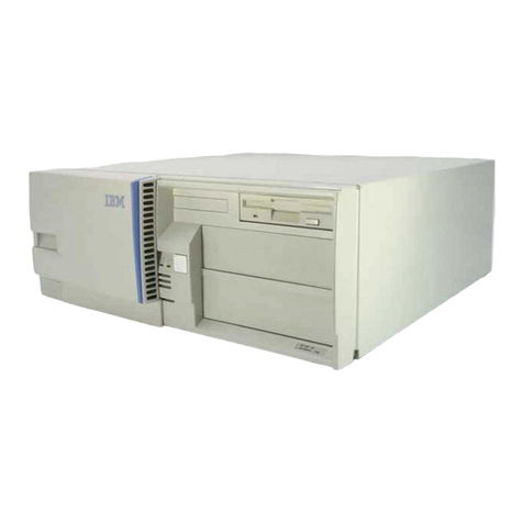
IBM Personal System/2 50 Use and care manual


First
Edition (May, 1988)
The following paragraph does not apply
to
the United Kingdom
or
any country where
such provisions
are
Inconsistent with local law: INTERNATIONAL BUSINESS MACHINES
CORPORATION PROVIDES THIS PUBLICATION "AS IS" WITHOUT WARRANTY
OF
ANY
KIND.
EITHER
EXPRESS
OR
IMPLIED. INCLUDING.
BUT
NOT
LIMITED
TO.
THE
IMPLIED
WARRANTIES
OF
MERCHANTABILITY
OR
FITNESS
FOR
A PARTICULAR
PURPOSE.
Some states do not
allow
disclaimer
of
express
or
implied warranties in certain
transactions. therefore.
this
statement may not applyto you.
This publication could include technical inaccuracies
or
typographical errors. Changes
are
periodically made
to
the information herein; these changes
will
be incorporated in
new
editions of the publication. IBM may make improvements and/or changes in the
product(s) and/orthe program(s) described in this publication at any time.
It is possible that this publication may contain reference to.
or
information about. IBM
products (machines and programs). programming.
or
services that are not announced
in your country. Such references
or
information must not be construed
to
mean that
IBM intends to announce such IBM products. programming.
or
services in your country.
THE PUBLICATION
OFTHE
INFORMATION CONTAINED HEREIN IS NOT INTENDED TO
AND DOES NOT CONVEY ANY RIGHTS OR LICENSES, EXPRESS OR IMPLIED, UNDER
ANY
IBM
PATENTS, COPYRIGHTS, TRADEMARKS,
MASK
WORKS OR ANY OTHER
INTELLECTUAL PROPERTY RIGHTS.
Requests for copies ofthis publication and for technical information about IBM
products should
be
made
to
your IBM Authorized Dealer
or
your IBM Marketing
Representative.
Personal System/2 is a registered trademark ofthe International Business Machines
Corporation.
© Copyright International Business Machines Corporation
1988.
All rights reserved.
No part ofthis work may be reproduced
or
distributed in any form
or
by any means
without
prior
permission in writing from the IBM Corporation.

Preface
The Technical Reference library is intended
for
those who develop
hardware and software products for IBM Personal Computers and
IBM Personal System/2. Users should understand computer
architecture and programming concepts.
This technical reference provides hardware and software interface
information
for
the IBM Personal System/2 Model
50
and should be
used with the following publications:
IBM Personal Systeml2 Hardware Interface Technical Reference
IBM Personal Systeml2 and Personal Computer BIOS Interface
Technical Reference
This manual consists of the following sections:
Section
1,
"System Overview," describes the system, features
and specifications.
Section
2,
"Programmable Option Select," describes registers
used
for
configuration.
Section
3,
"System Board," describes the system specific
hardware implementations.
Warning: The term "Reserved" describes certain signals, bits, and
registers that should not be changed. Use of reserved areas can
cause compatibility problems, loss of data,
or
permanent damage to
the hardware. When the contents of a register are changed, the state
of the reserved bits must be preserved. When possible, read the
register first and change only the bits that must be changed.
For information about components
or
devices not described in this
manual, refer to the Hardware Interface Technical Reference.
Information about diskette drives, fixed disk drives, adapters, and
external options are in separate option technical references.
III

Notes:
Iv

Contents
Section 1. System Overview
........................
1-1
Description
....................................
1-3
System Board Features
............................
1-3
System Board Block Diagram
........................
1-5
System Board I/O Address Map
......................
1-6
Specifications
..................................
1-7
Section 2. Programmable Option Select
.........
. . . . . . . .
2-1
Description
....................................
2-3
POS
Address Map
....................
. . . . . . . . . .
..
2-5
Card Selected Feedback
...........................
2-6
System Board Setup
..............................
2-6
System Board Enable/Setup Register (Hex
0094)
.........
2-7
System Board
POS
Register 2 (Hex
0102)
..............
2-8
System Board
POS
Register 3 (Hex
0103)
..............
2-9
Adapter Enable/Setup Register (Hex
0096)
............
2-10
Section 3. System Board
...........................
3-1
Description
....................................
3-3
Micro Channel
..................................
3-3
Adapter Identification
...........................
3-3
Central Arbiter
................................
3-3
Memory
......................................
3-7
Read-Only Memory Subsystem
.....................
3-7
Random Access Memory Subsystem
.................
3-7
Real-Time Clock/Complementary Metal-Oxide Semiconductor
RAM
.....................................
3-12
Miscellaneous System Functions
...
. . . . . . . . . . . . . . . .
..
3-24
Nonmaskable Interrupt . . . . . . . . . . . . . . . . . . . . . . . .
..
3-24
System Control Port B (Hex
0061)
..................
3-24
System Control Port A (Hex
0092)
..................
3-26
Power-On Password
...........................
3-28
Type 2 Serial Port Controller
.......................
3-29
Hardware Compatibility
...........................
3-29
Index
........................................
X-1
v

Notes:
vi

Figures
1-1.
Model and Submodel Bytes
...................
1-3
1-2.
System Board Devices and Features
.............
1-4
1-3.
System Board
............................
1-5
1-4.
System Board I/O Address Map
................
1-6
1-5.
Performance Specifications -Type 1 System Board
..
1-7
1-6.
Performance Specifications -Type 2 System Board
..
1-8
1-7.
Physical Specifications
......................
1-9
2-1.
POS
I/O Address Map
.......................
2-5
2-2. Card Selected Feedback Register (Hex
0091)
.......
2-6
2-3. System Board Enable/Setup Register (Hex
0094)
.....
2-7
2-4. System Board
POS
Register 2 (Hex
0102)
..........
2-8
2-5. Parallel Port Select Bits
.....................
2-8
2-6. System Board
POS
Register (Hex
0103)
...........
2-9
2-7. Adapter Enable/Setup Register (Hex
0096)
........
2-10
3-1. Arbitration Bus Priority Assignments
.............
3-4
3-2. Arbitration Register, Write to Hex
0090
...........
3-5
3-3. Arbitration Register, Read Hex
0090
.............
3-5
3-4. System Memory Map
.......................
3-8
3-5. System Board Memory Connector, Type 1
.........
3-9
3-6. System Board Memory Connector, Type 2
........
3-10
3-7. Presence Detect Encoding
...................
3-11
3-8. RT/CMOS RAM Address Map
.................
3-12
3-9. RT/CMOS Address Register and NMI Mask (Hex
0070)
3-13
3-10. RT/CMOS Data Register (Hex
0071)
.............
3-13
3-11. Real-Time Clock Bytes
.....................
3-15
3-12. Status Register A
.........................
3-16
3-13. Status Register B
.........................
3-16
3-14. Status Register C
.........................
3-18
3-15. Status Register D
.........................
3-18
3-16. Diagnostic Status Byte
.....................
3-19
3-17. Diskette Drive Type Byte
....................
3-20
3-18. Diskette Drive Type Byte (Bits 7 -
4)
............
3-21
3-19. Diskette Drive Type Byte (Bits 3 -
0)
............
3-21
3-20. Equipment Byte
..........................
3-22
3-21. Equipment Byte (Bits
7,
6)
...................
3-22
3-22. Equipment Byte (Bits
5,
4)
...................
3-22
3-23. System Control Port B (Write)
.................
3-25
3-24. System Control Port B (Read)
.................
3-25
3-25. System Control Port A (Hex
0092)
..............
3-26
vII
Notes:
vIII

Section 1. System Overview
Description
....................................
1-3
System Board Features
............................
1-3
System Board Block Diagram
........................
1-5
System Board I/O Address Map
......................
1-6
Specifications
..................................
1-7
Model
50
System Overview
1-1

Notes:
1-2
Model 50 System
Overview

Description
The IBM Personal System/2 Model
50
is a self-contained, desktop
computer system with a keyboard. It can support two diskette drives
and one internal fixed disk drive.
A system can have either a Type 1
or
Type 2 system board. The
major differences between the system boards are component layout
and memory. Programs identify the type by reading the model and
submodel bytes and BIOS revision code. Interrupt hex
15,
function
code (AH) = hex
CO,
returns the model and submodel bytes and BIOS
revision code. The following figure shows these bytes and the
system board types.
Model Submodel Revision
Byte Byte Code System Board
FC
04
00
Type 1
FC
04 03
Type 2
Figure 1-1. Model and Submodel Bytes
Refer to the IBM Personal System/2 and Personal Computer BIOS
Interface Technical Reference for a listing of other systems, and
check the supplements section
for
updates to that listing.
System Board Features
The following figure lists the system board devices and features. The
Hardware Interface Technical Reference describes devices common
to PS/2 products by type number.
Model
50
System Overview 1-3

Device
Microprocessor
System Tlmen
ROM Subaystem
RAM Subsystem
CMOS RAM
Subsystem
Video Subsystem
Audio Subsystem
DMA Controller
Interrupt
Contro"er
Keyboard/Auxl"ary
Device
Controller
Dlskene Drive
Contro"er
Type
Serial
Contro"er
1,
2**
Para"el
Contro"er
Micro
Channel
Math Coprocessor
Socket
Power Supply
Features
80286
24-bit address and 16-bitdata interface
Channel 0 - System
timer
Channel 2 - Tone generation
for
speaker
Channel 3 - Watchdog
timer
128KB (KB = 1024 bytes)
1MB -Type 1and 2 System Boards *
(MB = 1,048,576 Bytes)
Expandable on the channel
Type 2 can be expanded on the system
board
to
2MB
64-byte CMOS RAM with
real-time clock/calendar
Battery backup
Auxiliary
connector on the channel
Analog output
256KB video memory
Driven by:
-System-timer channel 2
-The 'audio sum node' signal.
Eight independent DMA channels
Single
or
burst transfers and read verification
16 levels
of
system interrupts
Interrupts
are
level-sensitive
Keyboard connector
AUXiliary device connector
Password
security
Supports:
-720KB formatted diskette density
-1.44MB formatted diskette density.
RS-232C Interface
Programmable
as
serial
port 1
or
2
Programmable
as
parallel
port
1,
2,
or
3
Supports bidirectional input and output
Four channel connectors:
-8-
or
16-bit device support
-One with an
auxiliary
video extension
-One occupied
by
the fixed
disk
drive
adapter
Supports
80287
math coprocessor
Same clock speed as the system
microprocessor
110
and
220
Vac support
*Some modelS support 2MB on the Type 2 system board.
••
The Model 50 does not support
the
FIFO mode.
Figure
1-2.
System Board Devices and Features
1-4 Model
50
System Overview

System Board Block Diagram
16
-Level
Interrupt
,----
Controller
Diskette
l-
I
ROM
I
Controller
I--I--
......
-3
Channel
Video
I--
Timer
L Graphics
I--I--
Array
:::
IDRAMI
f-
Kybd/Aux.
Device
80287 Controller
Coprocessor Serial
I--
(optional) t-- Port
I--
I-
......
-CMOS
Memory Clock
Controller
l-
I DMA .b- Parallel
I--I--
-
Controller Port
r-
Buffer I M
I I
iCC
B Control Buffer c h
u a 0
80288 f Data r n
Microprocessor f Address o n
n n
e e e
r Multidevice Interface
I
'-
I c
t
I Clock I 0
m Bus Central r
Controller Arbitration Point s
Oscillator
Figure 1-3. System Board
Model
50
System Overview 1-5

System
Board
1/0
Address
Map
Hex Addre
....
0000 -
oo1F
0020,0021
0040, 0042 -0044, 0047
0060
0061
0064
0070,0071
0081
-0083, 0087
0089,OO8A,008B,008F
0090
0091
0092
0094
0096
OOAO-
00A1
OOCO-
OODF
OOFO-
OOFF
0100 -
0107
01FO
-
01FS
027S- 027B
02FS
-02FF
037S
-037B
0384,
O3B5,
O3BA
OOBC- 03BF
03CO-
OOC5
O3C6
-03C9
03CA, 03CC, 03CE, 03CF
0304,
03D5,
03DA
03FO-
03F7
O3FS
-OOFF
Device
DMA
Controller
(0 -3)
Interrupt
Controller
(Master)
System
Timers
Keyboard,
Auxiliary
Device
System Control Port B
Keyboard,
Auxiliary
Device
RT/CMOS and NMI Mask
DMA Page Registers (0 -
3)
DMA Page Registers (4 -
7)
Central
Arbitration
Control Point
Card Selected Feedback Register
System Control Port A
System Board Enable/Setup Register
Adapter Enable/Setup Register
Interrupt
Controller
(Slave)
DMA
Controller
(4 -
7)
Math Coprocessor
Programmable Option Select
Fixed Disk Drive
Controller
Parallel Port 3
Serial Port 2 (RS-232C)
Parallel Port 2
Video Subsystem
Parallel Port 1
Video Subsystem
Video DAC
Video Subsystem
Video Subsystem
Diskette Drive
Controller
Serial Port 1 (RS-232C)
Figure
1-4.
System Board
110
Address Map
1-6 Model 50 System Overview

Specifications
Device
Microprocessor (10 MHz -100 na Clock):
Access
to
System Board RAM
Access to System Board
ROM
Access to Channel:
Default Transfer Cycle:
110
Access
Memory Access
Synchronous Extended Transfer Cycle
Refreah Rate
(Typically performed every
15.1
Jls)
Bua Maater Aceeaa
to
System Board RAM
DMA Controller(10 MHz -100 na Clock):
Number
of
Walta
1
o
1
Single Transfer:
300
+
110
Access + Memory Access
Burst Transfers: 300 +
(110
Access +Memory Access)N •
System Board Memory Access
Default Transfer Cycle:
110
Access
Memory Access
Synchronous Extended Transfer Cycle
• N is the number oftransfers in the burst.
Cycle
Time (na)
300
300
300
200
300
500
(min)
300
(min)
300
300
200
300
Figure 1-5. Performance Specifications -Type 1 System Board
Model
50
System Overview 1-7

The Type 2 system board supports two speeds of system board
memory. Cycle times differ depending upon the speed. See
Figure
3-7
on page
3-11.
DeYlce
Mlcroproceaaor (10 MHz -100
ns
Clock):
Access to System Board RAM:
85-ns Memory
120-ns Memory
Access to System Board
ROM
Access
to
Channel:
Default Transfer Cycle:
110
Access
Memory Access
Synchronous Extended Transfer Cycle
Refreah Rate
(Typically performed
every
15.1
jls)
Bua Master Accesa
to
System Board RAM
DMA Controller (10 MHz -100 na Clock):
Number
of
Walta
o
1
1
o
Single Transfer:
300
+
110
Access +Memory Access
Burst Transfers:
300
+
(110
Access +
Memory
Access)N •
System Board Memory Access
85-ns
Memory
120-ns Memory
Default Transfer Cycle:
110
Access
Memory Access
Synchronous Extended Transfer Cycle
• N is the number
of
transfers in the burst.
Cycle
Time (na)
200
300
300
300
200
300
500
(min)
300
(min)
200
300
300
200
300
Figure 1-6. Performance Specifications -Type 2 System Board
1-8 Model
50
System Overview

Size:
Width
Depth
Height
Weight
Cables:
Power Cable
Keyboard Cable
Air
Temperature:
System On
System Off
Humidity:
System On
System Off
Maximum Aftltude
Heat Output
Acoustical Readings
from
1 m (3.28 H):
Operating
Idle
Electrical:
Power Supply Input
Low Range
High Range
Maximum Current Draw:
Low Range
High Range
Frequency
Maximum Allowable Current:
Keyboard Port
Auxiliary
Device Port
Electromagnetic Compatibility
360
mm
(14.1
in)
420 mm (16.5 in)
140
mm (5.5 in)
9.55 kg
(21
Ib)
1.8 m (6 ft)
1.8 m(6 tt)
15.6 to 32.2"C (60 to 90°F)
10.0 to 43.0°C
(50
to 110°F)
8%
to
80%
20%
to
80%
2133.6 m (7000 ft)
144.8W
46
dB
average
40
dB
average
90 (min) -
137
(max)Vac
180
(min) -
265
(max)Vac
2.7
A
1.4A
50
-60Hz ±3Hz
275mA
300mA
FCC
Class B
Figure 1-7. Physical Specifications
Model
SO
System Overview 1-9

Notes:
1-10 Model
50
System Overview

Section
2.
Programmable Option Select
Description
....................................
2-3
P~S
Address Map
..
. . . . . . . . . . . . . . . . . . . . . . . . . . . . . . 2-5
Card Selected Feedback
...........................
2-6
System Board Setup
..............................
2-6
System Board Enable/Setup Register (Hex
0094)
.........
2-7
System Board
P~S
Register 2 (Hex 0102)
..............
2-8
System Board
P~S
Register 3 (Hex
0103)
..............
2-9
Adapter Enable/Setup Register (Hex
0096)
............
2-10
Model 50
POS
2-1

Notes:
2-2 Model 50 POS
Table of contents
Other IBM Desktop manuals

IBM
IBM NetVista A21 Service manual

IBM
IBM 5155 User manual

IBM
IBM NetVista A20 User manual

IBM
IBM PC 300GL Types 6275 Quick start guide

IBM
IBM NetVista A21 User manual

IBM
IBM NetVista A21 Service manual

IBM
IBM 6862 - PC 300 PL User manual

IBM
IBM MICRO TOWER 2169 Owner's manual

IBM
IBM Power System S822 Instruction Manual

IBM
IBM 3270 Installation manual

IBM
IBM NetVista A22p User manual

IBM
IBM 7012 300 Series Installation and maintenance instructions

IBM
IBM NetVista Owner's manual

IBM
IBM PC 300GL Types 6275 Technical manual

IBM
IBM ThinkPad 380 Owner's manual

IBM
IBM NetVista A20 Guide

IBM
IBM PC 300 Mounting instructions

IBM
IBM IntelliStation 6866 Owner's manual

IBM
IBM Aptiva User manual

IBM
IBM NetVista X40 User manual