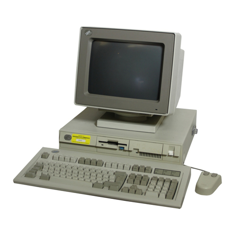
IBM RT PC 10 Owner's manual

----
----
--
---
---
-----
---
---
-----
--_.-
Personal
Computer
Hardware
Reference
Library
IBM
RT
PC
Model
10
Hardware
Maintenance
and
Service
59X9319

----
----
--
---
---
--
---
---
---
-----
--_.-
Personal
Computer
Hardware Reference
Library
IBM
RT
PC
Model
10 Hardware
Maintenance and Service

NOTICE
TO
USER
The Diagnostic Diskettes (Diag 1and Diag 2) referred to in this manual are
located in the IBM
RT
PC
Problem Determination Guide binder.
First Edition November
1985
Changes are made periodically to the information herein; these changes will be incorporated in new editions of this publication.
References in this publication to IBM products, programs,
or
services do not imply that IBM intends to make these available in all countries
in which IBM operates. Any reference to an IBM program product in this publication
is
not intended to state
or
imply that only IBM's
program product may be used. Any functionally equivalent program may be used instead.
International Business Machines Corporation provides this manual "as is," without awarranty of any kind, either expressed
or
implied,
including, but not limited to, the implied warranties of merchantability and fitness for aparticular purpose. IBM may make improvements
and/or
changes in the product(s)
and/or
the program(s) described in this manual at any time.
Products are not stocked at the address given below. Requests for copies
of
this product and for technical information about the system
should be made to your authorized IBM RT PC Model 10 dealer.
Areader's comment form
is
provided at the back
of
this publication.
If
the form has been removed, address comments to IBM
Corporation, Department 998, 11400 Burnet Road, Austin, Texas 78758. IBM may use or distribute whatever information you supply in
any way it believes appropriate without incurring any obligation to you.
©Copyright International Business Machines Corporation 1985

Federal
Communications
Commission (FCC) Radio Frequency
Interference Statement
Warning:
This equipment has been tested and found
to
comply with
the limits for aClass Acomputing device pursuant to Subpart Jof
Part
15
of
FCC
Rules, which are designed to provide reasonable
protection against such interference when operated in acommercial
environment. Operation of this equipment in aresidential area
is
likely to cause interference, in which case the user
at
his own expense
will be required to take whatever measures may
be
required to correct
the interference.
This equipment generates, uses, and can radiate radio frequency energy.
If
not
installed and used according to the instruction manual, the equipment
may cause interference to radio communications. It has
been
tested and
found to comply with the limits for aClass Acomputing device pursuant
to
Subpart J
of
Part
15
of
FCC
Rules, which are designed to provide
reasonable protection against such interference when operated in a
commercial environment. Operation of this equipment in aresidential area
is
likely to cause interference, in which case the user
at
his own expense will
be required to take whatever measures may be required to correct the
interference.
If
this equipment causes interference to radio communications, which can be
determined by turning the equipment off and on, the user
is
encouraged to
try to correct the interference
by
one
or
more of the following measures:
•Reorient the receiving antenna.
•Relocate the equipment with respect to the receiver.
•Move the equiplnent away from the receiver.
•Plug the computer into adifferent outlet, so that the computer and
receiver are
on
different branch circuits.
•Ensure that card mounting screws, attachment connector screws,
and
ground wires are tightly secured.
iii

iv
Service Manual
•Ensure that card slot covers are
in
place when no card
is
installed.
•
If
peripherals not offered by IBM are used with this equipment, it is
suggested to use shielded, grounded cables with in-line filters, if
necessary.
If
necessary, consult your dealer service representative for additional
suggestions.
The manufacturer
is
not responsible for any radio or television interference
caused
by
unauthorized modifications to this equipment.
It
is
the
responsibility of the user to correct such interference.

Safety
This manual contains
"DANGER"
notices
on
pages 4-22 and 4-23.
If
desired, translate the text and write your own words
on
the pages.
This manual contains a"Safety Inspection Guide"
on
the following pages.
The Safety Inspection Guide
is
used by the IBM Service Representative.
The IBM
RT
PC
Model 10 System Unit contains no hazardous voltages
or
safety grounds outside the power supply. The power supply
is
asealed unit
and
is
not field serviceable.
Safety v

Safety Inspection
Guide
Use this guide to identify unsafe conditions. Use good judgment to identify
potential safety hazards not covered by this guide.
If
unsafe conditions are
present, determine how serious the hazards are and whether you should
continue before correcting the problem.
Do the following checks:
1.
Check the covers for damage
or
alterations that expose the internal
parts of the system unit
or
for sharp edges.
2. Check the covers for proper fit to the system unit. They should be in
place and secure.
vi Service Manual

3. Set the power switch
on
the
system unit
to
Off.
4. Remove the rear cover (page 4-10).
5. Remove the
top
cover (page 4-12).
6.
Check for alterations
or
attachments.
If
there are any, check for
obvious safety hazards such as
broken
wires, sharp edges,
or
broken
insulation.
7. Check the internal cables for damage.
8. Check for dirt, water,
and
any
other
contamination within
the
system
unit.
Safety
vii

viii Service Manual
9.
Check the voltage label
on
the rear of the system unit to ensure it
matches the voltage at your outlet.
10. Check the external power cable for damage.
11. With the external power cable connected to the system unit, check for
less than 0.1 ohm resistance between the ground lug
on
the external
power cable plug and the metal frame
of
the power supply.
12. Install the top cover (page 4-13).
13. Install the rear cover (page 4-11).
Metal
Frame

About this
Book
This manual provides service information about the IBM RT
PC
Model 10
System Unit, adapters, and attached devices
that
do
not
have their own
service information. This manual does
not
contain service information
about attached printing devices.
Users of this manual should have training
on
the IBM
RT
PC
Model 10.
This manual
is
divided into sections to make the information easier
to
find.
Section
1,
"System Description" contains abrief description
of
the system
unit, keyboard, and display.
Section 2, "Diagnostics" contains descriptions of the diagnostic programs,
utilities, and the service request number.
Section 3, "Problem Isolation Charts" contains the service procedures used
to isolate failures to afield-replaceable unit.
Section 4, "Removal and Replacement Procedures" contains the locations,
removal procedures, and replacement procedures. These procedures may
direct you to another section for specific details such as switch settings,
jumper settings,
or
terminator resistor settings.
Section 5, "Base System Unit" contains adescription, specifications, cabling
diagrams, adata flow diagram, and parts information for the base
components of the system unit.
Section 6, "System Memory Options" contains adescription, specifications,
and parts information for each system memory option.
About this Book
ix

xService Manual
Section 7, "Diskette Drive" contains adescription, specifications,
terminator resistor setting, and parts information for the diskette drive.
Section 8, "Fixed-Disk Drive" contains adescription, specifications,
terminator resistor setting, and parts information for the fixed-disk drive.
Section 9, "Adapters" contains adescription, specifications, switch
or
jumper settings, and parts information for each adapter used in the system
unit.
Section 10,
"User
Input Devices" contains adescription, specifications, a
removal procedure, areplacement procedure, and parts information for each
type device used to input data or commands.
Section 11, "Displays" contains adescription, specifications, control
adjustment procedures, and parts information for each IBM display used
with the IBM
PC
RT
Model 10.
Section 12,
"Tape
Drive" contains adescription, specifications, and parts
information for the tape drive used with the IBM
PC
RT
Model 10.
Appendix A, "Tool Requirements" contains descriptions of the tools needed
to service the IBM
PC
RT
Model 10.
Appendix B,
"SRA
to
FRU
Cross-Reference List" contains alist of each
Service Repair Action (SRA) number and the part number and part name
of
the field-replaceable unit it represents. This list
is
in SRA number order.
AReader's Comment
Form
and Book Evaluation
Form
are provided at the
back of this book. Use the Reader's Comment
Form
at any time to give
IBM information that may improve the book. After you become familiar
with the book, use the Book Evaluation Form to give IBM specific feedback
about the book.

Related
Publications
•
IBM
RT
PC
Guide
to
Operations describes the Model 10, Model 20, and
Model 25 system units, the displays, keyboard, and other devices that
can be attached. This guide also includes procedures for operating the
hardware and moving the Model 10, Model 20, and Model 25 system
units.
•
IBM
RT
PC
User
Setup Guide provides instructions for setting up and
connecting devices to the system units. This
book
also gives procedures
for testing the setup and for installing the AIX Operating System.
•
IBM
RT
PC
Options Installation provides instructions for installing
optional adapters in Model 10, Model 20, and Model 25 and installing
fixed-disk and diskette drives in Model 20 and Model 25.
•
IBM
RT
PC
Problem Determination Guide provides instructions for
running diagnostic routines to locate and identify hardware problems.
Also includes problem determination for software. Two high-capacity
(1.2MB) diskettes containing the IBM
RT
PC
diagnostic routines are
included.
•
IBM
RT
PC
Hardware Technical Reference
is
atwo-volume set.
Volume Idescribes how the system unit operates, including
1/0
interfaces, serial ports, memory interfaces, and
CPU
interface
instructions. Volume II describes adapter interfaces for optional
devices and communications and includes information about IBM
Personal Computer family options and the adapters supported
by
Model
10, Model 20, and Model 25. (Available optionally)
•
IBM
6157
Streaming Tape Drive Setup and Operating Instructions
provides instructions for setting up and operating the IBM 6157
Streaming Tape Drive. This pamphlet also describes procedures for
cleaning the recording head
of
the tape drive and handling tape
cartridges.
About this Book
xi

•Setup Instructions for the
IBM
PC
Network Short, Medium, and Long
Distance Kits provides instructions for setting up and connecting the
short, medium, and long distance expanders.
•Setup Instructions for the
IBM
PC
Network Transformer and Translator
Unit provides instructions for setting up and connecting the transformer
and translator.
Ordering
Additional
Copies
of
This
Book
To order additional copies
of
this publication, use either of the following
sources:
•To order from your IBM representative, use Order Number SV21-8026.
•To order from your
mM
dealer, use Part Number 6280745.
Abinder and wrap plugs are included with the order.
xii Service Manual

Contents
Section 1. System Description
1-1
About this Section 1-3
Introduction 1-4
System Unit 1-4
Keyboard 1-5
Display 1-6
Section 2. Diagnostics
2-1
About this Section 2-3
Introduction to Diagnostics ................................
..
2-4
Power-On Self-Test 2-7
Standalone Diagnostic Program Descriptions 2-8
Loading the Diagnostic Diskette 2-8
Key Descriptions 2-9
Diagnostic Routines 2-10
Utilities 2-12
Advanced Diagnostic Routines 2-15
Installation Verification 2-16
Service Request Number Description 2-17
Source Number 2-18
Service Repair Action Number 2-19
Section 3. Problem Isolation Charts
3-1
About this Section 3-3
Introduction 3-4
Start of Call PIC 3-5
Problem Determination Procedure 3-22
Memory Expansion Option PIC 2100 3-62
Power Supply PIC 8800 3-68
POST Errors 03
or
05 PIC 9810 3-79
POST Errors 00 or 04 PIC 9820 3-87
POST Errors
11
or 12 PIC 9830 3-92
POST Error 23 PIC 9840 3-96
Contents xiii

xiv
Service Manual
Invalid Display Data PIC 9850 3-100
Undetermined Problem PIC 9860 . .
..
3-104
Service Repair Action Number Chart 3-109
Section 4. Removal and Replacement Procedures
4-1
About this Section 4-3
System Unit Locations 4-4
Front View With Covers 4-4
Rear View Without Rear Cover 4-5
Top View Without Covers 4-6
System Board 4-7
Handling Static-Sensitive Devices 4-8
Removal and Replacement Procedures 4-10
Rear Cover Removal 4-10
Rear Cover Replacement 4-11
Top Cover Removal 4-12
Top Cover Replacement 4-13
Processor, Floating-Point,
or
System Memory Removal 4-14
Processor, Floating-Point,
or
System Memory Replacement 4-15
Adapter Removal 4-16
Adapter Replacement 4-18
Attached Device Removal 4-20
Attached Device Replacement 4-21
Battery Removal 4-22
Battery Replacement 4-23
Diskette Drive Removal 4-24
Diskette Drive Replacement 4-26
Fixed-Disk Drive Removal 4-28
Fixed-Disk Drive Replacement 4-30
Keylock Removal 4-32
Keylock Replacement 4-33
Operator Panel Board Removal 4-34
Operator Panel Board Replacement 4-35
Cooling
Fan
Assembly Removal 4-36
Cooling
Fan
Assembly Replacement 4-37
Power Supply Removal 4-38
Power Supply Replacement 4-40
System Board Removal 4-42
System Board Replacement 4-46

Section 5. Base System Unit
5-1
About this Section 5-3
Base System Unit (6151) 5-4
Specifications 5-4
Removal and Replacement Procedures 5-4
Processor Board 5-5
Floating-Point Board 5-5
System Board 5-6
Data Flow Diagram .................................
..
5-7
Power Distribution Diagram 5-8
Internal Signal Cabling Diagram 5-9
Parts Information 5-10
Section 6. System Memory Options
6-1
About this Section 6-3
System Memory Option Chart 6-4
1MB
Memory Expansion Option 6-5
Specifications 6-5
Removal and Replacement Procedures 6-5
Parts Information 6-6
2MB Memory Expansion Option 6-7
Specifications 6-7
Removal and Replacement Procedures 6-7
Parts Information 6-8
Section 7. Diskette Drive 7
-1
About this Section 7-3
Personal Computer AT High Capacity Diskette Drive 7-4
Specifications 7-4
Removal and Replacement Procedures 7-4
Terminator Resistor 7-5
Parts Information 7-6
Section 8. Fixed-Disk Drive
8-1
About this Section 8-3
Fixed-Disk Drive Type R40 8-4
Specifications 8-4
Removal and Replacement Procedures 8-4
Terminator Resistor 8-5
Contents
xv

xvi
Service Manual
Parts Information 8-6
Section 9. Adapters 9-1
About this Section 9-4
Personal Computer
AT
Coprocessor Option 9-5
Specifications 9-5
Removal and Replacement Procedures 9-5
Parts Information 9-6
AT 512
KB
Memory Expansion Option 9-7
Specifications 9-7
Removal and Replacement Procedures
9-
7
Switch Settings 9-8
Parts Information 9-9
Personal Computer
AT
Fixed-Disk and Diskette Drive Adapter 9-10
Specifications 9-10
Removal and Replacement Procedures 9-10
Jumper Settings 9-11
Parts Information 9-12
ffiM Monochrome Display and Printer Adapter 9-13
Specifications 9-13
Removal and Replacement Procedures 9-13
Parts Information 9-14
Advanced Monochrome Graphics Display Adapter 9-15
Specifications 9-15
Removal and Replacement Procedures 9-15
Parts Information 9-16
Enhanced Graphics Adapter 9-17
Specifications 9-17
Removal and Replacement Procedures 9-17
Switch and Jumper Settings 9-18
Parts Information 9-19
4Port Asynchronous RS232C Adapter 9-20
Specifications 9-20
Removal and Replacement Procedures 9-20
Switch Settings 9-21
Parts Information 9-22
4Port Asynchronous RS422 Adapter 9-23
Specifications 9-23
Removal and Replacement Procedures 9-23
Switch Settings 9-24

Parts Information 9-25
ffiM
PC
Network Adapter (5178) 9-26
Specifications 9-26
Removal and Replacement Procedures 9-26
Jumper Settings ......................................
..
9-27
Parts Information 9-28
Personal Computer
AT
Serial/Parallel Adapter 9-30
Specifications 9-30
Removal and Replacement Procedures 9-30
Jumper Module Settings 9-31
Parts Information 9-32
Streaming Tape Drive Adapter 9-33
Specifications 9-33
Removal and Replacement Procedures 9-33
Parts Information 9-34
3278/79
Emulation Adapter 9-35
Specifications 9-35
Removal and Replacement Procedures 9-35
Parts Information 9-36
Section 10. User Input Devices 10-1
About this Section
.............•.........................
10-3
Keyboard 10-4
Specifications 10-4
Removal Procedure 10-4
Replacement Procedure 10-4
Parts Information 10-5
Mouse 10-6
Specifications 10-6
Removal Procedure 10-6
Replacement Procedure 10-6
Parts Information 10-7
Section 11. Displays 11-1
About this Section 11-3
ffiM Personal Computer Display (5151) 11-4
Specifications 11-4
Removal and Replacement Procedures 11-4
Test Patterns 11-5
Parts Information 11-7
Contents
xvii

xviii
Service Manual
Advanced Monochrome Graphics Display (6153) 11-9
Specifications 11-9
Removal and Replacement Procedures 11-9
Parts Information 11-10
Enhanced Color Display (5154) 11-11
Specifications 11-11
Removal and Replacement Procedures 11-11
Adjustments 11-12
Test Patterns 11-14
Parts Information 11-16
Section 12. TapeDrive
12-1
About this Section 12-3
Streaming Tape Drive (6157) 12-4
Specifications 12-4
Removal and Replacement Procedures 12-4
Parts Information 12-5
Appendix
A.
Tool Requirements
A-I
Wrap Plugs
A-I
Module Puller A-4
Multimeter A-4
Appendix B. SRA to
FRU
Cross-Reference List
B-1
Glossary .
X-I
Index
X-7

Section
1.
System Description
System Description 1-1
Table of contents
Other IBM Desktop manuals

IBM
IBM 3179 User manual

IBM
IBM NetWista A60 Type 6838 User manual

IBM
IBM NetVista X40 Instruction Manual

IBM
IBM 5170 Use and care manual

IBM
IBM Aptiva 2158 Owner's manual

IBM
IBM NetVista X40 User manual

IBM
IBM NetVista A30 User manual

IBM
IBM NetVista 2289 User manual

IBM
IBM ThinkCentre A30 8198 User manual

IBM
IBM NetVista Owner's manual

IBM
IBM NetVista A22p User manual

IBM
IBM NetVista A21 Service manual

IBM
IBM IntelliStation A Pro User manual

IBM
IBM NetVista A30 User manual

IBM
IBM RAMAC 305 User manual

IBM
IBM 525 User manual

IBM
IBM 3290 User manual

IBM
IBM PC 300GL Types 6275 User manual

IBM
IBM NetVista A21 User manual

IBM
IBM IntelliStation M Pro User manual