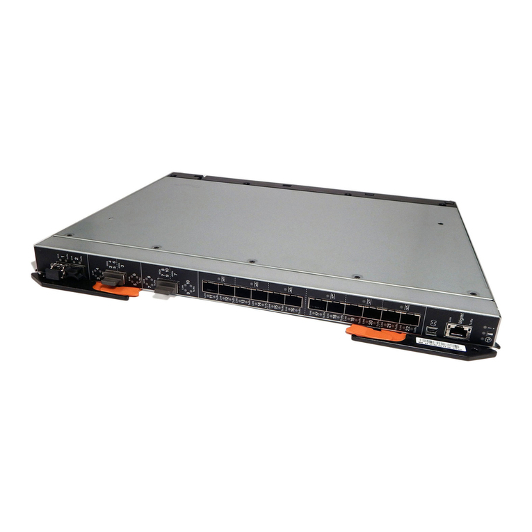
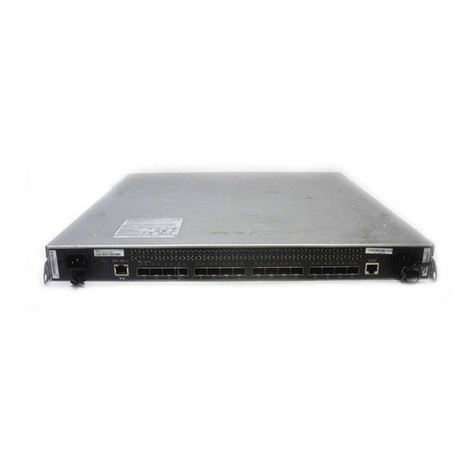
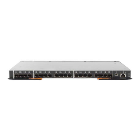
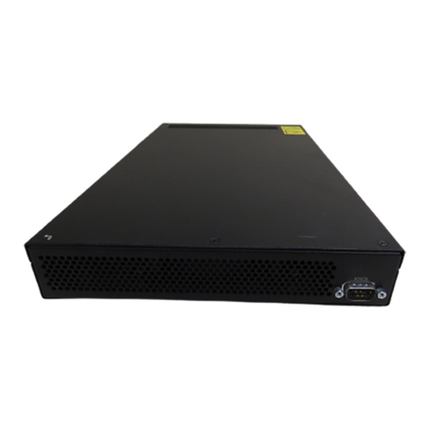
IBM SAN32M-2 Manual

IBM TotalStorage SAN32M-2
Installation and Service Manual
Service information: 2026 /432, 32E
GC26-7763-01
Read Before Using
This product contains software that is licensed under written license agreements. Your use of such software is subject to
the license agreements under which they are provided.


IBM TotalStorage SAN32M-2
Installation and Service Manual
Service information: 2026 /432, 32E
GC26-7763-01

Note:
Before using this information and the product it supports, read the information in the Notices section.
Second Edition (March 2006)
This edition replaces all previous versions. This edition includes information about RoHS compliance and part
numbers.
The following paragraph does not apply to any country (or region) where such provisions are inconsistent with local
law.
INTERNATIONAL BUSINESS MACHINES CORPORATION PROVIDES THIS PUBLICATION “AS IS” WITHOUT
WARRANTY OF ANY KIND, EITHER EXPRESS OR IMPLIED, INCLUDING, BUT NOT LIMITED TO, THE IMPLIED
WARRANTIES OF MERCHANTABILITY OR FITNESS FOR APARTICULAR PURPOSE. Some states (or regions) do
not allow disclaimer of express or implied warranties in certain transactions; therefore, this statement may not apply
to you.
Order publications through your IBM
®
representative or the IBM branch office serving your locality.
©Copyright International Business Machines Corporation 2005, 2006. All rights reserved.
US Government Users Restricted Rights –Use, duplication or disclosure restricted by GSA ADP Schedule Contract
with IBM Corp.

© Copyright IBM Corp. 2006 vii
Contents
About this book ........................................................................................................ xvii
Chapter 1 General information
Switch description ...............................................................................1
Field replaceable units .................................................................2
SFP transceiver..............................................................................3
Power supply assembly...............................................................4
Controls, connectors, and indicators.................................................5
RESET button ................................................................................5
Ethernet LAN connector..............................................................5
Power and system error LEDs ....................................................6
CRU status LEDs ..........................................................................6
Maintenance port..........................................................................6
Chassis ground connector ...........................................................6
Switch specifications ...........................................................................7
Maintenance approach........................................................................8
Switch management ............................................................................9
Management server......................................................................9
Management server specifications...........................................10
Ethernet hub (optional).............................................................. 11
Error-detection, reporting, and serviceability features ................12
Tools and test equipment..................................................................13
Tools used with the product......................................................13
Tools supplied by service personnel........................................15
Chapter 2 Installation tasks
Factory defaults..................................................................................17
Installation task summary ................................................................17
Task 1: Verify installation requirements .........................................19
Task 2: Unpack, inspect, and install the Ethernet hub (optional)20
Unpack and inspect Ethernet hub............................................20
Desktop installation....................................................................20
Rack-mount installation.............................................................22
Task 3: Unpack, inspect, and install the product...........................23
Unpack and inspect switch .......................................................23
Desktop installation....................................................................24
Rack-mount installation.............................................................25

SAN32M-2 Installation and Service Manual
viii
Task 4: Configure product at the EFCM Basic Edition interface
(optional)............................................................................................. 26
Configure product identification ............................................. 28
Configure date and time............................................................ 28
Configure parameters ................................................................ 29
Configure fabric parameters ..................................................... 31
Configure network information ............................................... 32
Configure basic port information............................................. 34
Configure port BB_Credit.......................................................... 35
Configure port NPIV.................................................................. 36
Configure SNMP ........................................................................ 36
Enable CLI ................................................................................... 38
Enable or disable host control................................................... 38
Configure SSL encryption ......................................................... 39
Install PFE keys (optional) ........................................................ 40
Configure security ...................................................................... 43
Configure interswitch links....................................................... 44
Task 5: Configure product network information (optional)........ 45
Task 6: Configure server password and network addresses ....... 48
Configure password................................................................... 48
Configure private LAN addresses ........................................... 49
Configure public LAN addresses (optional) .......................... 50
Task 7: Configure management server information ..................... 51
Access the management server desktop ................................. 51
Configure management server names..................................... 52
Configure gateway and DNS server addresses ..................... 53
Task 8: Configure Windows operating system users.................... 54
Change default administrator password ................................ 55
Add a new user........................................................................... 55
Change user properties.............................................................. 56
Task 9: Set management server date and time .............................. 57
Task 10: Configure the call-home feature (optional)..................... 59
Task 11: Assign user names and passwords .................................. 60
Task 12: Configure the product to the management application 62
Task 13: Record or verify server restore information ................... 63
Task 14: Verify product-to-server communication........................ 64
Task 15: Configure PFE key (optional) ........................................... 66
Task 16: Configure management server (optional)....................... 67
OSMS............................................................................................ 68
FMS............................................................................................... 68
Task 17: Set product date and time ................................................. 70
Task 18: Configure the Element Manager application ................. 72
Configure product identification ............................................. 72

ix
Contents
Configure product parameters..................................................73
Configure fabric parameters......................................................75
Configure ports ...........................................................................76
Configure SNMP.........................................................................78
Configure threshold alerts .........................................................80
Enable EFCM Basic Edition and Telnet access........................83
Configure, enable, and test e-mail notification.......................83
Configure and enable Ethernet events.....................................84
Configure, enable, and test call-home event notification......85
Configure security ......................................................................86
Configure interswitch links .......................................................87
Task 19: Back up configuration data................................................87
Task 20: Cable Fibre Channel ports .................................................90
Task 21: Configure zoning (optional) ..............................................91
Task 22: Connect product to a fabric element (eptional) ..............91
Chapter 3 Maintenance analysis procedures
Factory defaults ..................................................................................95
Quick start ...........................................................................................95
MAP 0000: Start MAP......................................................................100
MAP 0100: Power distribution analysis........................................105
MAP 0200: POST failure analysis ..................................................107
MAP 0300: Loss of server communication ...................................109
MAP 0400: Part failure analysis .....................................................119
MAP 0500: Port failure or link incident analysis .........................122
MAP 0600: Fabric or ISL problem analysis...................................134
Chapter 4 Repair information
Procedural notes...............................................................................149
Power on switch ...............................................................................149
Power off switch...............................................................................151
IML or reset switch ..........................................................................151
IML..............................................................................................152
Reset............................................................................................152
Clean fiber-optic components ........................................................153
Download firmware.........................................................................154
Port LED diagnostics .......................................................................155
Repair procedures - EFCM Basic Edition .....................................156
Obtain log information.............................................................156
Perform port fiagnostics...........................................................159
Collect maintenance data.........................................................165

SAN32M-2 Installation and Service Manual
x
Set online state .......................................................................... 166
Block or unblock a port............................................................ 167
Upgrade firmware.................................................................... 168
Manage configuration data ..................................................... 170
Repair procedures - SAN management application................... 173
Obtain Fabric Log information............................................... 174
Obtain Switch Log information.............................................. 175
Perform port diagnostics......................................................... 178
Collect maintenance data ........................................................ 187
Set online state .......................................................................... 189
Block or unblock a port............................................................ 189
Upgrade firmware.................................................................... 190
Manage configuration data ..................................................... 193
Install or upgrade software..................................................... 197
Chapter 5 Removal and replacement procedures
Procedural notes .............................................................................. 201
ESD procedures................................................................................ 201
Customer-replaceable unit: SFP optical transceiver................... 202
Field-replaceable unit: Redundant power supply ...................... 206
Chapter 6 Illustrated parts breakdown
RoHS Information .................................................................... 211
Front-accessible FRUs ..................................................................... 212
Rear-accessible FRUs....................................................................... 213
Power cords and receptacles .......................................................... 215
Appendix A Event code tables
System events (000 through 199) .................................................. 220
Power supply events (200 through 299) ...................................... 237
Fan events (300 through 399) ........................................................ 240
CTP card events (400 through 499) .............................................. 247
Port events (500 through 599) ....................................................... 253
Thermal sensor events (800 through 899) ................................... 262
Notices ......................................................................................................................... 265
Trademarks ....................................................................................... 267
Electronic emission notices............................................................. 267
Laser Compliance Statement .................................................. 267
Federal Communications Commission (FCC) Class A State-

xi
Contents
ment ............................................................................................268
Industry Canada Class A Emission Compliance Statement.....
268
Avis de conformité à la réglementation d’Industrie Canada ...
268
European Union (EU) Electromagnetic Compatibility Direc-
tive...............................................................................................268
Germany Electromagnetic Compatibility Directive ............269
People’s Republic of China Class A Electronic Emission State-
ment ............................................................................................270
Korean Class A Electronic Emission Statement ...................270
Japan VCCI Class A ITE Electronic Emission Statement ....270
Index................................................................................................................................271

SAN32M-2 Installation and Service Manual
xii

© Copyright IBM Corp. 2006 xiii
Figures
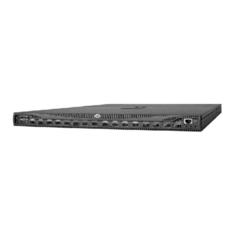
1 SAN32M-2 (front view) ................................................................................... 3
2 SAN32M-2 (rear view) ..................................................................................... 3
3 24-Port Ethernet hub ...................................................................................... 11
4 Door key .......................................................................................................... 14
5 Loopback plug ................................................................................................ 14
6 Fiber-optic protective plug ........................................................................... 14
7 Null modem cable .......................................................................................... 15
8 Patch cable and MDI selector configuration .............................................. 21
9 Mounting bracket installation (Ethernet hub) ........................................... 22
10 Hardware View .............................................................................................. 27
11 Identification View ......................................................................................... 28
12 Date Time View .............................................................................................. 29
13 Parameters View ............................................................................................. 30
14 Fabric Parameters View ................................................................................. 31
15 Network View ................................................................................................. 33
16 Basic Information View ................................................................................. 35
17 SNMP View ..................................................................................................... 37
18 CLI View .......................................................................................................... 38
19 OSMS View ..................................................................................................... 39
20 SSL View .......................................................................................................... 40
21 Maintenance Feature Installation View ...................................................... 42
22 Connection Description dialog box ............................................................. 46
23 Identification Changes Dialog Box .............................................................. 52
24 Internet Protocol (TCP/IP) Properties dialog box ..................................... 54
25 Add New User wizard .................................................................................. 56
26 Properties dialog box (General tab) ............................................................. 57
27 Date/Time Properties dialog box (Time Zone tab) ................................... 58
28 Date/Time Properties dialog box (Date & Time tab) ............................... 59
29 Add User dialog box ...................................................................................... 61
30 Address Properties dialog box (IP Address page) .................................... 62
31 Hardware View .............................................................................................. 65
32 New Feature Key dialog box ........................................................................ 67
33 Configure FICON Management Server dialog box ................................... 69
34 Configure FICON Management Server Zoning dialog box ..................... 70
35 Configure Date and Time dialog box .......................................................... 71
36 Configure Identification dialog box ............................................................ 73
37 Configure Switch Parameters dialog box ................................................... 74
38 Configure Fabric Parameters dialog box .................................................... 75
39 Configure Ports dialog box ........................................................................... 77

SAN32M-2 Installation and Service Manual
xiv
40 Configure SNMP dialog box ........................................................................ 79
41 New Threshold Alert dialog box (screen 1) ............................................... 80
42 New Threshold Alert dialog box (screen 2) ............................................... 81
43 New Threshold Alert dialog box (screen 3) ............................................... 82
44 Email Event Notification Setup dialog box ................................................ 83
45 InCD icon (unformatted CD) ........................................................................ 88
46 Daisy-Chained Ethernet Hubs ................................................................... 113
47 Clean fiber-optic components .................................................................... 153
48 Port List View ............................................................................................... 159
49 Diagnostics View .......................................................................................... 163
50 System Files View ........................................................................................ 165
51 Switch View .................................................................................................. 167
52 Basic Information View ............................................................................... 168
53 Firmware Upgrade View ............................................................................ 169
54 Backup Configuration View ....................................................................... 171
55 Restore Configuration View ....................................................................... 172
56 Port List View ............................................................................................... 179
57 Port Properties dialog box .......................................................................... 181
58 Port Technology dialog box ........................................................................ 183
59 Port Diagnostics dialog box ........................................................................ 184
60 Swap Ports dialog box ................................................................................. 187
61 Save Data Collection dialog box ................................................................ 188
62 Set Online State dialog box ......................................................................... 189
63 Firmware Library dialog box ..................................................................... 191
64 Backup and Restore Configuration dialog box ........................................ 194
65 Reset Configuration dialog box ................................................................. 195
66 Discover Setup dialog box .......................................................................... 196
67 Address Properties dialog box ................................................................... 196
68 InstallShield Wizard dialog box ................................................................. 199
69 SFP optical transceiver removal and replacement .................................. 204
70 Redundant power supply removal and replacement ............................. 207
71 Front-accessible SFPs ................................................................................... 212
72 Rear-accessible FRUs ................................................................................... 213
73 Power cords and receptacles ...................................................................... 215

© Copyright IBM Corp. 2006 xv
Tables
1 IBM products and SAN management documentation—E/OS ........... xviii
2 Factory-set defaults (product) ...................................................................... 17
3 Installation task summary ............................................................................. 18
4 Operational states and symbols ................................................................... 64
5 Factory-set defaults ........................................................................................ 95
6 MAP summary ............................................................................................... 95
7 Event codes versus maintenance action ...................................................... 96
8 MAP 100 event codes ................................................................................... 105
9 MAP 200 Event Codes ................................................................................. 107
10 MAP 200 Byte 0 CRU Codes ....................................................................... 108
11 MAP 300 error messages ............................................................................. 112
12 MAP 400 event codes ................................................................................... 120
13 MAP 500 event codes ................................................................................... 122
14 Link incident messages ................................................................................ 123
15 Invalid attachment reasons and actions .................................................... 124
16 Inactive port reasons and actions ............................................................... 130
17 MAP 600 event codes ................................................................................... 135
18 E_Port segmentation reasons and actions ................................................ 137
19 Port fence codes and actions ....................................................................... 142
20 Fabric merge failure reasons and actions ................................................. 146
21 Port operational states ................................................................................. 155
22 Rear-accessible FRU parts list ..................................................................... 213
23 Power cord and receptacle list ................................................................... 216

SAN32M-2 Installation and Service Manual
xvi

© Copyright IBM Corp. 2006 xvii
About this book
This publication is part of a documentation suite that supports the
IBM TotalStorage SAN32M-2 switch.
Who should use this manual
Use this publication if you are a trained installation and service
representative experienced with the switch, storage area network
(SAN) technology, and Fibre Channel technology.
The IBM TotalStorage SAN32M-2 switch contains no
customer-serviceable parts that require internal access to the product
during normal operation or prescribed maintenance conditions. In
addition, refer to this manual for instructions prior to performing any
maintenance action.
Related publications
Other publications that provide additional information about the
switch include:
•IBM TotalStorage Products in a SAN Environment Planning Manual,
GC26-7675.
•EFC Manager Software Release 8.7 User Manual, 620-000170.
•SANavigator Software Release 4.2 User Manual 621-000013.
•EFCM Basic Edition User Manual, 620-000240.
•SNMP Support Manual, 620-000131.
•E/OS Command Line Interface User Manual, 620-000134.
•IBM TotalStorage SANC40M Cabinet Installation and Service Manual,
GC26-7746.
•IBM eServer Safety Notices, G229-9054.

SAN32M-2 Installation and Service Manual
xviii
IBM and McDATA publications
Some of the documentation that is applicable to IBM TotalStorage
products is provided by McDATA Corporation. The documents often
are identified by a McDATA product name that corresponds to the
IBM product name. Table 1 lists the IBM product name, the
corresponding McDATA product name, the applicable software, and
the documentation that is relevant to the product.
Table 1 IBM products and SAN management documentation—E/OS
IBM TotalStorage
product name,
and machine type
and model
McDATA product
name
Related firmware
and SAN
management
product Relevant documentation
SAN12M-1 Switch
• 2026-E12
• 2026-12E
Sphereon 4300
Switch
•E/OS
• EFCM Basic
Edition
•EFCM Basic Edition User Manual (620-000240)
•E/OS SNMP Support Manual (620-000131)
•E/OS Command Line Interface User Manual (620-000134)
SAN24M-1 Switch
• 2026-224
Sphereon 4500
Switch
•E/OS
•EFCM
• Element
Manager
• EFCM Basic
Edition
•EFC Manager Software Release 8.7 User Manual,
620-000170.
•Sphereon 4500 Switch Element Manager User Manual
(620-000175)
•EFCM Basic Edition User Manual (620-000240)
•E/OS SNMP Support Manual (620-000131)
•E/OS Command Line Interface User Manual (620-000134)
SAN32M-1 Switch
• 2027-232
Sphereon 3232
Switch
•E/OS
•EFCM
• Element
Manager
• EFCM Basic
Edition
•EFC Manager Software Release 8.7 User Manual,
620-000170.
•Sphereon 3032 and 3232 Fabric Switch Element Manager
User Manual (620-000173)
•EFCM Basic Edition User Manual (620-000240)
•E/OS SNMP Support Manual (620-000131)
•E/OS Command Line Interface User Manual (620-000134)
SAN16M-2 Switch
• 2026-416
• 2026-16E
Sphereon 4400
Switch
•E/OS
•EFCM
• Element
Manager
• EFCM Basic
Edition
•EFC Manager Software Release 8.7 User Manual,
620-000170.
•Sphereon 4400 Switch Element Manager User Manual
(620-000241)
•EFCM Basic Edition User Manual (620-000240)
•E/OS SNMP Support Manual (620-000131)
•E/OS Command Line Interface User Manual (620-000134)

xix
About this book
Ordering manuals
To order a printed copy of this publication, contact your IBM Branch
office or you can locate (and purchase) books online at:
http://www.elink.ibmlink.ibm.com/public/applications/
publications/cgibin/pbi.cgi?
Where to get help
Contact IBM for technical support, which includes hardware support,
all product repairs, and ordering of spare parts, go to:
http://www.ibm.com/servers/storage/support/san/index.html.
You can also contact IBM within the United States at 1-800-IBMSERV
(1-800-426-7378). For support outside the United States, you can find
the service number at http://www.ibm.com/planetwide/.
SAN32M-2 Switch
• 2026-432
• 2026-32E
Sphereon 4700
Switch
•E/OS
•EFCM
• Element
Manager
• EFCM Basic
Edition
•EFC Manager Software Release 8.7 User Manual,
620-000170.
•Sphereon 4700 Switch Element Manager User Manual
(620-000242)
•EFCM Basic Edition User Manual (620-000240)
•E/OS SNMP Support Manual (620-000131)
•E/OS Command Line Interface User Manual (620-000134)
SAN140M director
• 2027-140
Intrepid 6140
director
•E/OS
•EFCM
• Element
Manager
• EFCM Basic
Edition
•EFC Manager Software Release 8.7 User Manual,
620-000170.
•Intrepid 6140 and 6064 Directors Element Manager User
Manual (620-000153)
•EFCM Basic Edition User Manual (620-000240)
•E/OS SNMP Support Manual (620-000131)
•E/OS Command Line Interface User Manual (620-000134)
Table 1 IBM products and SAN management documentation—E/OS (Continued)
IBM TotalStorage
product name,
and machine type
and model
McDATA product
name
Related firmware
and SAN
management
product Relevant documentation

SAN32M-2 Installation and Service Manual
xx
How to send your comments
Your feedback is important in helping us provide the most accurate
and high-quality information. If you have comments or suggestions
for improving this document, you can send us comments
electronically by using the following addresses:
• Internet: starpubs@us.ibm.com
• IBMLink™ from U.S.A.: STARPUBS at SJEVM5
• IBMLink from Canada: STARPUBS at TORIBM
• IBM Mail Exchange: USIB3VVD at IBMMAIL
You can also mail your comments by using the Reader Comment
Form in the back of this manual or direct your mail to:
International Business Machine Corporation
Information Development
Department GZW
9000 South Rita Road
Tucson, Arizona 85744-001 U.S.A
When you send information to IBM, you grant IBM a nonexclusive
right to use or distribute the information in any way it believes
appropriate without incurring any obligation to you.
Safety and environmental notices
ATTENTION ! The SAN32M-2 is designed to be installed by customers. It
has no customer-serviceable parts, however, and must be serviced by
qualified service representatives.
Safety notices and labels
When using this product, observe the danger, caution, and attention
notices contained in this guide. The notices are accompanied by
symbols that represent the severity of the safety condition. The
danger and caution notices are listed in numerical order based on
their IDs, which are displayed in parentheses, for example (D004), at
the end of each notice. Use this ID to locate the translations of these
danger and caution notices in the IBM eServer Safety Notices

xxi
About this book
(G229-9054) publication, which is on the CD-ROM that accompanies
this product.
The following notices and statements are used in this document. They
are listed below in order of increasing severity of potential hazards.
Follow the links for more detailed descriptions and examples of the
danger, caution, and attention notices in the sections that follow.
•Note: These notices provide important tips, guidance, or advice.
•Attention notices: These notices indicate potential damage to
programs, devices, or data.
•Caution notices: These statements indicate situations that can be
potentially hazardous to you.
•Danger notices: These statements indicate situations that can be
potentially lethal or extremely hazardous to you. Safety labels are
also attached directly to products to warn of these situations.
Danger notices A danger notice calls attention to a situation that is potentially lethal
or extremely hazardous to people. A lightning bolt symbol
accompanies a danger notice to represent a dangerous electrical
condition. Read and comply with the following danger notices before
installing or servicing this device.
DANGER
To prevent a possible shock from touching two surfaces with different
protective ground (earth), use one hand, when possible, to connect or
disconnect signal cables.
(D001)
DANGER
Overloading a branch circuit is potentially a fire hazard and a shock
hazard under certain conditions. To avoid these hazards, ensure that
your system electrical requirements do not exceed branch circuit
protection requirements. Refer to the information that is provided
with your device or the power rating label for electrical
specifications.
(D002)

SAN32M-2 Installation and Service Manual
xxii
DANGER
If the receptacle has a metal shell, do not touch the shell until you
have completed the voltage and grounding checks. Improper wiring
or grounding could place dangerous voltage on the metal shell. If any
of the conditions are not as described, STOP. Ensure the improper
voltage or impedance conditions are corrected before proceeding.
(D003)
DANGER
An electrical outlet that is not correctly wired could place hazardous
voltage on metal parts of the system or the devices that attach to the
system. It is the responsibility of the customer to ensure that the
outlet is correctly wired and grounded to prevent an electrical shock.
(D004)
A comprehensive danger notice provides instructions on how to
avoid shock hazards when servicing equipment. Unless instructed
otherwise, follow the procedures in the following danger notice.
DANGER
Electrical voltage and current from power, telephone, and
communication cables are hazardous. To avoid a shock hazard:
• Do not connect or disconnect any cables or perform installation,
maintenance, or reconfiguration of this product during an
electrical storm.
• Connect all power cords to a properly wired and grounded
electrical outlet. Ensure outlet supplies proper voltage and phase
rotation according to the system rating plate.
• Connect any equipment that will be attached to this product to
properly wired outlets.
• When possible, use one hand only to connect or disconnect signal
cables.
• Never turn on any equipment when there is evidence of fire,
water, or structural damage.
• Disconnect the attached power cords, telecommunications
systems, networks, and modems before you open the device
covers, unless instructed otherwise in the installation and
configuration procedures.
Other manuals for SAN32M-2
1
Table of contents
Other IBM Switch manuals

IBM
IBM 8265 Nways ATM Switch Technical specifications

IBM
IBM SAN32M-2 User manual

IBM
IBM RackSwitch G8000 User manual

IBM
IBM Multi-Port USB Hub User manual

IBM
IBM Global console manager User manual

IBM
IBM EN4093R User manual

IBM
IBM Brocade FCoE User manual

IBM
IBM SAN32M1 Manual

IBM
IBM 8270 Installation and maintenance instructions

IBM
IBM TotalStorage 3534-F08 User manual