Icom IC-2100H User manual

INSTRUCTION MANUAL
i2100H
144 MHz FM TRANSCEIVER
This device complies with Part 15 of the FCC rules. Operation is sub-
ject to the following two conditions: (1) This device may not cause
harmful interference, and (2) this device must accept any interference
received, including interference that may cause undesired operation.

ii
FOREWORD
Thank you for purchasing this Icom product. The IC-2100H/-T
144 MHz FM TRANSCEIVER is designed and built with Icom’s
superior technology and craftsmanship. With proper care this
product should provide you with years of trouble-free operation.
IMPORTANT
READ ALL INSTRUCTIONS carefully and com-
pletely before using the transceiver.
SAVE THIS INSTRUCTION MANUAL—This in-
struction manual contains important operating instructions for
the IC-2100H/-T.
EXPLICIT DEFINITIONS
RWARNING! NEVER connect the transceiver to an
AC outlet. This may pose a fire hazard or result in an electric
shock.
RWARNING! NEVER operate the transceiver while
driving a vehicle. Safe driving requires your full attention—
anything less may result in an accident.
NEVER connect the transceiver to a power source of more
than 16 V DC. This will ruin the transceiver.
NEVER connect the transceiver to a power source using
reverse polarity. This will ruin the transceiver.
NEVER cut the DC power cable between the DC plug and
fuse holder. If an incorrect connection is made after cutting,
the transceiver may be damaged.
NEVER place the transceiver where normal operation of
the vehicle may be hindered or where it could cause bodily
injury.
NEVER let objects impede the operation of the cooling fan
on the rear panel.
DO NOT push the PTT when not actually desiring to transmit.
DO NOT allow children to play with any radio equipment
containing a transmitter.
WORD DEFINITION
RWARNING Personal injury, fire hazard or electric
shock may occur.
CAUTION Equipment damage may occur.
NOTE If disregarded, inconvenience only. No risk
of personal injury, fire or electric shock.
CAUTIONS

During mobile operation, DO NOT operate the transceiver
without running the vehicle’s engine. When transceiver power
is ON and your vehicle’s engine is OFF, the vehicle’s battery
will soon become exhausted.
BE CAREFUL! The transceiver will become hot when
operating it continuously for long periods.
AVOID using or placing the transceiver in direct sunlight or
in areas with temperatures below –10°C (+14°F) or above
+60°C (+140°F).
AVOID the use of chemical agents such as benzine or al-
cohol when cleaning, as they can damage the transceiver’s
surfaces.
USE Icom microphones only (supplied or optional). Other
manufacturer’s microphones have different pin assignments
and may damage the transceiver if attached.
For U.S.A. only
Caution: Changes or modifications to this transceiver, not ex-
pressly approved by Icom Inc., could void your authority to
operate this transceiver under FCC regulations.
iii
SUPPLIED ACCESSORIES
➀DC power cable . . . . . . . . . . . . . . . . . . . . . . . . . . . . . . . 1
➁Mobile mounting bracket . . . . . . . . . . . . . . . . . . . . . . . . . 1
➂Microphone (HM-118T*) . . . . . . . . . . . . . . . . . . . . . . . . . 1
➃Fuse (20 A) . . . . . . . . . . . . . . . . . . . . . . . . . . . . . . . . . . . 1
➄Mounting screws, nuts and washers . . . . . . . . . . . . . 1 set
➅Mic hanger (depending on version) . . . . . . . . . . . . . . . . 1
*The microphone illustrated above is the HM-118T.
HM-97 . . . . . . . . . . . . Europe versions
HM-98S . . . . . . . . . . . USA, Taiwan versions
HM-118 . . . . . . . . . . . Asia, Australia versions
HM-118T . . . . . . . . . . Thailand, LatinAmerica, Korea versions
HM-118TA . . . . . . . . . some USAversions
➀➁ ➂
➃
➄
1
4
78
0
M#
9C
D
56B
23A

iv
FOREWORD ................................................................................... ii
IMPORTANT .................................................................................... ii
EXPLICIT DEFINITIONS ................................................................. ii
CAUTIONS ...................................................................................... ii
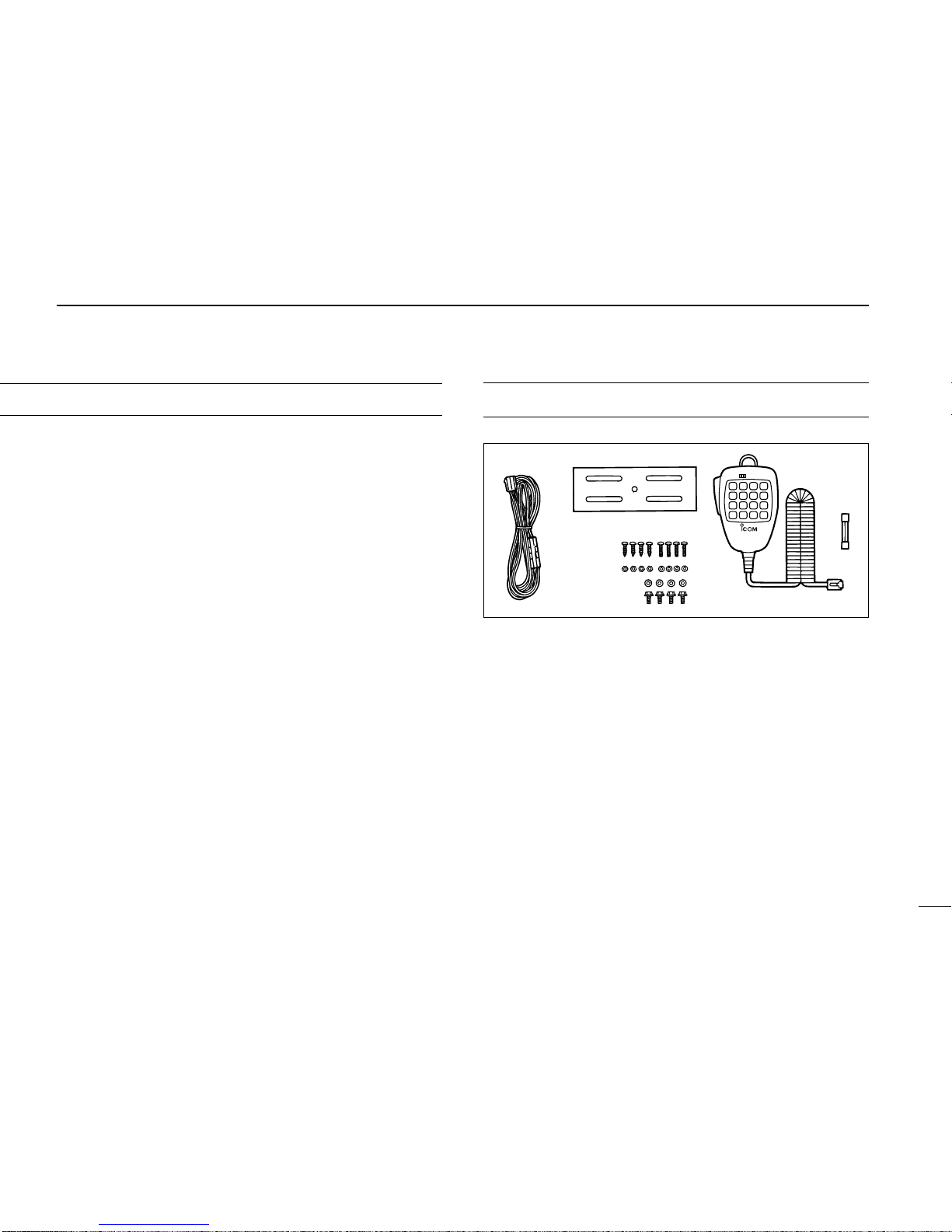
SUPPLIED ACCESSORIES ........................................................... iii
TABLE OF CONTENTS .................................................................. iv
1 PANEL DESCRIPTION .......................................................... 1–8
■Front panel .............................................................................. 1
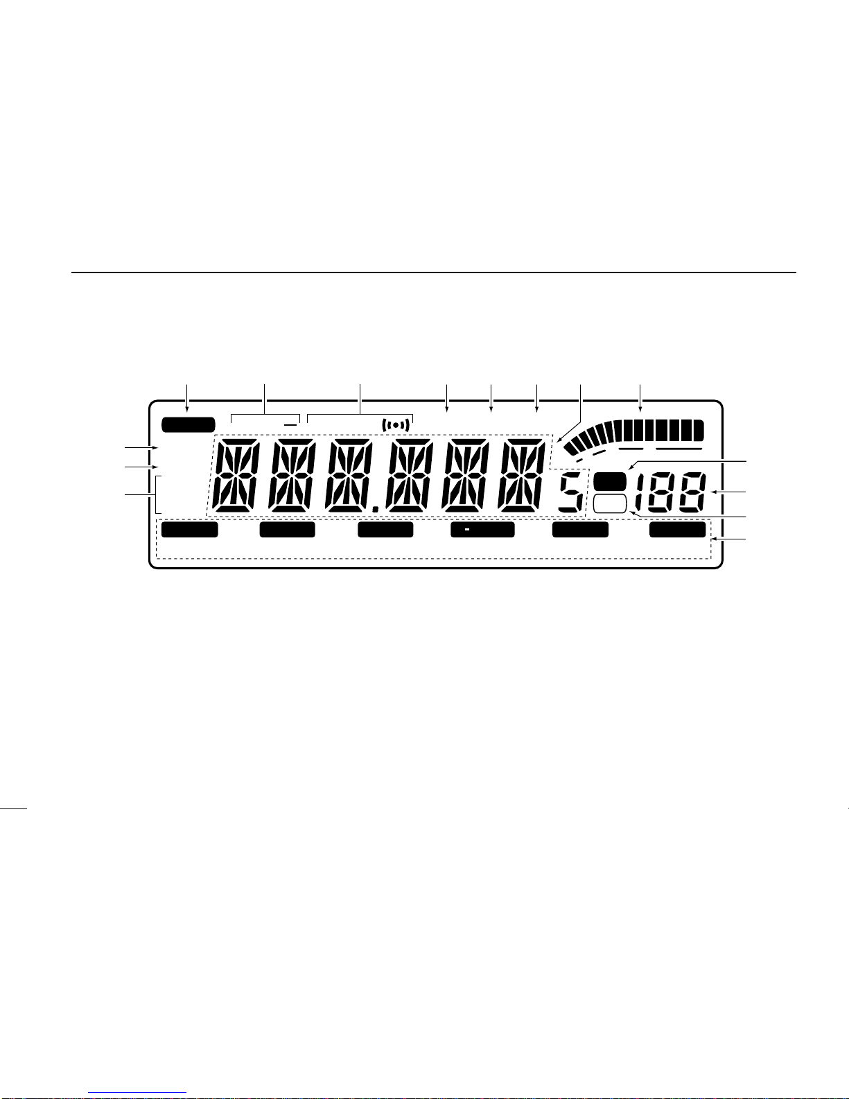
■Function display ...................................................................... 3
■Rear panel .............................................................................. 5
■Microphone ............................................................................. 6
■Microphone keypad ................................................................. 7
2 INSTALLATION .................................................................... 9–11
■Location .................................................................................. 9
■Using the mounting bracket .................................................... 9
■Battery connection ................................................................ 10
■DC power supply connection ................................................ 10
■Antenna installation ............................................................... 11
3 SETTING A FREQUENCY ................................................. 12–16
■Preparation ........................................................................... 12
■Lock functions ....................................................................... 13
■Using the tuning dial ............................................................. 14
■Using the [Y]/[Z] keys .......................................................... 14
■Tuning step selection ............................................................ 15
■Using the keypad .................................................................. 16
TABLE OF CONTENTS
4 BASIC OPERATION .......................................................... 17–19
■Receiving .............................................................................. 17
■Monitor function .................................................................... 17
■Audio mute function .............................................................. 17
■Transmitting .......................................................................... 18
■Selecting output power ......................................................... 18
■One-touch PTT function ........................................................ 19
5 REPEATER OPERATION .................................................. 20–24
■Accessing a repeater ............................................................ 20
■Subaudible tones .................................................................. 22
■Offset frequency .................................................................... 23
■Auto repeater ........................................................................ 24
■Repeater lockout ................................................................... 24
6 MEMORY OPERATION ...................................................... 25–30
■General description ............................................................... 25
■Memory channel selection .................................................... 25
■Programming a memory channel .......................................... 26
■
Programming a memory channel via the microphone ........... 27
■Transferring memory contents .............................................. 28
■Clearing a memory ................................................................ 29
■Alphanumeric display ............................................................ 30
7 CALL CHANNEL OPERATION ......................................... 32–33
■Calling up the call channel .................................................... 32
■Transferring call channel contents ........................................ 32
■Programming the call channel .............................................. 33

v
8 SCRATCH PAD MEMORY ................................................. 34–35
■What is scratch pad memory? .............................................. 34
■Calling up a scratch pad memory ......................................... 34
■Transferring scratch pad memory contents ........................... 35
9 SCAN OPERATION ........................................................... 36–41
■Scan types ............................................................................ 36
■Scan start/stop ...................................................................... 37
■Programming scan edges ..................................................... 38
■Programming scan edges via the microphone ...................... 39
■Skip channel setting .............................................................. 40
■Scan resume condition ......................................................... 41
10 PRIORITY WATCH ............................................................ 42–43
■Priority watch types ............................................................... 42
■Priority watch operation ........................................................ 43
11 DTMF MEMORY ENCODER ............................................. 44–45
■Programming a DTMF code .................................................. 44
■Transmitting a DTMF code .................................................... 45
■DTMF speed ......................................................................... 45
12 POCKET BEEP AND TONE SQUELCH ........................... 46–48
■Pocket beep operation .......................................................... 46
■Tone operation ...................................................................... 47
■Tone scan .............................................................................. 48
13 WIRELESS OPERATION .................................................. 49–54
■Connection ............................................................................ 49
■HM-90
WIRELESS MICROPHONE
.............................................. 49
■EX-1759 installation .............................................................. 50
■HM-90 switches .................................................................... 51
■Microphone address ............................................................. 54
14 OTHER FUNCTIONS ......................................................... 55–59
■Beep tones ON/OFF ............................................................. 55
■Time-out timer ....................................................................... 55
■Auto power-off ....................................................................... 56
■Squelch delay ....................................................................... 56
■Microphone [F-1]/[F-2] keys .................................................. 57
■Demonstration display .......................................................... 57
■Display color ......................................................................... 58
■Display dimmer ..................................................................... 58
■FM narrow mode ................................................................... 58
■Data cloning .......................................................................... 59
15 MAINTENANCE ................................................................. 60–62
■Troubleshooting .................................................................... 60
■Fuse replacement ................................................................. 62
■Partial CPU resetting ............................................................ 62
■Resetting the CPU ................................................................ 62
16 SPECIFICATIONS ................................................................... 63
17 OPTIONS ........................................................................... 64–65
18 MODE ARRANGEMENT ................................................... 66–67

2
1PANEL DESCRIPTION
rVOLUME CONTROL [VOL]
Adjusts the audio level. (p. 18)
tTUNING DIAL
Selects the operating frequency (p. 15), the memory
channel (p. 26), the contents of the set mode display
and the scanning direction (p. 37).
yVFO/MHz SWITCH [V/MHz(SCAN)]
➥Selects and toggles VFO mode and the 1 MHz/10
MHz/TS tuning display. (p. 15)
➥Starts a scan when pushed and held for 1 sec.
(p. 37)
■Front panel
qSELECT MEMORY/MEMORY WRITE SWITCH
[S.MW(MW)]
➥Selects a memory channel for programming. (p. 26)
➥Programs selected memory when pushed and held.
(p. 27)
wPOWER SWITCH [PWR]
Turns power ON and OFF when pushed momentarily.
eSQUELCH CONTROL [SQL]
Varies the squelch level. (p. 18)
• The RF attenuator activates and increases the attenuation when
rotated clockwise to the center position and further.
SQL
VOL
PWR
S.MW
MW
Function display (p. 4)
uio!0!1!2
q
wer t
y
SCANPRIOTDUPANMLOCK
SCAN
V MHz
/
CALLMTONELOWMONISET
LOW
MID
NAR
MUTE DUP T SQL PRIO AO BUSY
/
M
TX
SKIP
9
5
1

3
1
PANEL DESCRIPTION
uMEMORY/CALL CHANNEL SWITCH [M/CALL(PRIO)]
➥Selects and toggles memory mode or the call channel.
(pgs. 26, 32)
➥Activates the priority watch function when pushed and
held. (p. 42)
iTONE/TONE SCAN SWITCH [TONE(T-SCAN)]
➥Each push selects a tone function. (p. 46)
• Tone encoder, pocket beep, tone squelch or tone func-
tion OFF can be selected.
➥Push and hold to start/stop the tone scan function.
(p. 48)
oOUTPUT POWER/DUPLEX SWITCH [LOW(DUP)]
➥Each push changes the output power selection. (p. 19)
• There are 3 output powers available: low, mid and high
(the IC-2100-T Thailand and IC-2100H Taiwan versions have
only 2 output powers).
➥Push and hold to select a duplex setting. (p. 21)
• There are 3 duplex settings available: minus duplex
(“DUP–” appears), plus duplex (“DUP” appears) and
simplex (no indicator appears).
!0 MONITOR/ALPHANUMERIC SWITCH [MONI(ANM)]
➥Toggles squelch opened and closed when pushed.
(p. 18)
➥In memory and call channel mode, toggles the alphanu-
meric channel indication ON and OFF. (p. 31)
!1 SET/LOCK SWITCH [SET(LOCK)]
➥Selects set mode when pushed.
➥Toggles the lock function ON and OFF when pushed
and held. (p. 14)
!2 MICROPHONE CONNECTOR
Connects the supplied microphone. (p. 7)
DMicrophone connector (front panel view)
➀+8 V DC output
➁Frequency up/down
➂NC (no connection)
➃PTT
➄GND (microphone ground)
➅MIC (microphone input)
➆GND
➇NC (no connection)
➀➇

4
1PANEL DESCRIPTION
■Function display
qTRANSMIT INDICATOR
➥Appears while transmitting. (p. 19)
➥Flashes while transmitting with the one-touch PTT func-
tion. (p.20)
wDUPLEX INDICATORS (p. 21)
“DUP–” or “DUP” appears during semi-duplex operation
(repeater operation).
eTONE INDICATORS
➥“T” appears while the subaudible tone encoder is in use.
(p. 21)
➥“T SQL” appears while the tone squelch function is in
use. (p.47)
➥“T SQLS” appears while the pocket beep function is
in use. (p. 46)
rPRIORITY WATCH INDICATOR (p. 42)
Appears while the priority watch is activated; flashes while
the watch is paused.
tAUTO POWER-OFF INDICATOR (p. 56)
Appears while the auto power-off function is in use.
yBUSY INDICATOR (p. 18)
Appears when a signal is being received or the squelch is
open ([MONI] is pushed).
uFREQUENCY READOUT
Shows the operating frequency, alphanumeric names, set
mode contents, etc.
• Frequency decimal point flashes while scanning. (p. 37)
SCANPRIOTDUPANMLOCK
SCAN
VMHz
/
CALLMTONELOWMONISET
LOW
MID
NAR
MUTE DUP T SQL PRIO AO BUSY
/
M
TX
SKIP
9
5
1
!3
!5
we i
!2
qrtyu
o
!0
!1
!4

5
1
PANEL DESCRIPTION
• “d” appears in place of the 100 MHz digit while the DTMF mem-
ory function is in use. (p. 44)
iS/RF INDICATORS
➥Show the relative signal strength while receiving signals.
(p. 18)
➥Show the output power while transmitting. (p. 19)
oMEMORY INDICATOR (p.26)
Appears when memory mode is selected.
!0 MEMORY CHANNEL READOUTS
➥Show the selected memory channel numbers.
➥A capital “L” appears while the frequency lock function
is in use. (p. 14)
➥“C” appears while the call channel is selected. (p. 32)
➥One of “L1” to “L3” appears when a simplex scratch pad
memory is selected. (p. 34)
➥One of “r1” to “r3” appears when a duplex scratch pad
memory is selected. (p. 34)
➥A small “c” appears when VFO mode is selected from
the call channel or a scratch pad memory.
!1 SKIP INDICATOR
Appears when the displayed memory channel is specified
as a skip channel. (p. 40)
!2 SWITCH INDICATORS
Indicate the function(s) of the front panel switches directly
below the function display.
!3 OUTPUT POWER INDICATORS (p. 19)
➥“MID” appears when mid output power is selected.
• The IC-2100T Thailand and IC-2100H Taiwan versions have
no mid output power.
➥“LOW” appears when low output power is selected
➥Neither indicator appears when high output power is se-
lected.
!4 NARROW FM MODE INDICATOR
Appears when narrow FM mode is selected (available with
the Europe version only; p. 58).
!5 AUDIO MUTE INDICATOR
Appears when the audio mute function is activated via mi-
crophone control.
• This function is cancelled when any switch or control is operated.

eANTENNA CONNECTOR [ANT]
Connects a 50 Ωantenna with a PL-259 connector and a
50 Ωcoaxial cable.
6
1PANEL DESCRIPTION
■Rear panel
qSPEAKER JACK [SP]
Accepts an 8 Ωspeaker.
• Audio output power is more than 2.4 W.
wPOWER RECEPTACLE [DC13.8V]
Accepts 13.8 V DC ±15% with the supplied DC power
cable.
• Current of 12A or greater is required.
☞NOTE: DO NOT use a cigarette lighter socket as a
power source when operating in a vehicle. The plug may
cause voltage drops and ignition noise may be superim-
posed onto transmit or receive audio.
e
w
q

7
1
PANEL DESCRIPTION
■Microphone (HM-98S*)
qUP/DOWN SWITCHES [Y]/[Z]
➥Push either switch to change operating frequency, mem-
ory channel, set mode contents, etc. (pgs. 15, 26)
➥Push and hold either switch to start scanning. (p. 37)
wPTT SWITCH
➥Push and hold to transmit; release to receive.
➥Toggles between transmitting and receiving while the
one-touch PTT function is in use. (p. 20)
LOCK
VFO
CALL
MR
MW
FUNC
A
CLR
D-OFF
B
SET
PTT-M
3
PRIO
DTMF
6
LOW
2
SCAN
5
MID
1
MONI
4
HIGH
T-OFF
C
ENT
TSQL
9
SIMP
16
KEY LOCK
#
TSQLS
8
DUP+
TONE-2
0
TONE
7
DUP–
TONE-1
F-2
F-1
B
DTMF-S
MUTE
D
Mic element
q
w
er t
y
u
i
o
eVFO SWITCH [VFO(LOCK)]
➥Push to select VFO mode.
➥Push and hold to toggle the lock function ON and OFF.
(p. 14)
rMEMORY SWITCH [MR(CALL)]
➥Push to select memory mode. (p. 26)
➥Push and hold to select the call channel. (p. 32)
tACTIVITY INDICATOR
➥Lights red while any key is pushed (except [FUNC] or
[DTMF-S].
➥Lights red while transmitting.
➥Lights green while the one-touch PTT function is in use.
yNULL SWITCH [B]
No function.
uFUNCTION SWITCHES [F-1]/[F-2] (p. 57)
Assign your desired key function from the front panel
switches.
• Default settings are [LOW] for [F-1] ([DUP] when pushed and
held) and [TONE] for [F-2] ([T-SCAN] when pushed and held).
iFUNCTION INDICATOR
➥Lights orange while [FUNC] is activated—indicates the
secondary function of switches can be accessed.
➥Lights green when [DTMF-S] is activated—DTMF sig-
nals can be transmitted with the keypad.
oKEYPAD
Used for controlling the transceiver, transmitting DTMF sig-
nals, etc. See the following 2 pages for details.
*
A different microphone
may be supplied depend-
ing on transceiver ver-

8
1PANEL DESCRIPTION
■Microphone keypad
KEY FUNCTION
Toggles between opening and closing the
squelch.
Starts and stops scanning. (p. 37)
Starts and stops priority watch. (p. 42)
Selects high output power. (p. 19)
Selects mid output power. (p. 19)
Selects low output power (p. 19)
Selects –duplex. (p. 21)
Selects + duplex. (p. 21)
Selects simplex. (p. 21)
No primary function.
SECONDARY FUNCTION (after )
No secondary function.
Turns the one-touch PTT function ON and
OFF. (p. 20)
No secondary function.
Turns the DTMF memory encoder function
ON. (p. 44)
Turns the subaudible tone encoder ON.
(p. 21)
Turns the pocket beep function ON.(p. 46)
Turns the tone squelch function ON.
(p. 46)
While being pushed, transmits a 1750 Hz
tone. (p. 22)
FUNC
OTHER FUNCTIONS
1
MONI
2
SCAN
PTT-M
3
PRIO
4
HIGH
5
MID
DTMF
6
LOW
TONE
7
DUP–
TSQLS
8
DUP+
TSQL
9
SIMP
TONE-2
0
After :
Transmit the appropriate
DTMF code or push [0] to
[9], [A] to [D] to transmit the
DTMF memory contents
when the DTMF memory
encoder is activated.(p. 22)
DTMF-S

9
1
PANEL DESCRIPTION
KEY FUNCTION
➥Clears a digit before entry. (p. 17)
➥Cancels the scan, priority watch or
DTMF memory function. (pgs. 16, 37,
43)
Enters set mode and advances the set
mode selection.
➥Sets the keypad for numeral input
(p. 17)
➥
Decreases the set mode selection order
after entering set mode.
No primary function.
SECONDARY FUNCTION (after )
➥Writes VFO contents into the memory
or call channel. (p. 29)
➥Advances the memory channel number
when continuously pushed after pro-
gramming is completed. (p. 28)
DTMF memory OFF.
Turns the subaudible tone encoder, pocket
beep or tone squelch OFF.(pgs. 21, 47, 46)
Mutes the audio. (p. 18)
• Mute function is released when any operation
is performed.
Locks the digit keys on the keypad (includ-
ing the A to D, # and Mkeys. (p. 14)
Sends a 1750 Hz tone signal for 0.5 sec.
(p. 22)
FUNC
OTHER FUNCTIONS
MW
A
CLR
D-OFF
B
SET
T-OFF
C
ENT
MUTE
D
16
KEY LOCK
#
TONE-1
M
After :
Transmit the appropriate
DTMF code. (p. 45)
DTMF-S
[A] to [D] transmit DTMF
memories. (p. 44)

10
2INSTALLATION
■Location
Select a location which can support the weight of the trans-
ceiver and does not interfere with driving in any way. We rec-
ommend the locations shown in the diagram below.
NEVER place the transceiver where normal operation of the
vehicle may be hindered or where it could cause bodily injury.
NEVER place the transceiver where air bag deployment may
be obstructed.
DO NOT place the transceiver where hot or cold air blows di-
rectly onto it.
AVOID placing the transceiver in direct sunlight.
■Using the mounting bracket
➀Drill 4 holes where the mounting bracket is to be installed.
• Approx. 5.5–6 mm (3⁄16") when using nuts; approx. 2–3 mm (1⁄16")
when using self-tapping screws.
➁Insert the supplied screws, nuts and washers through the
mounting bracket and tighten.
➂Adjust the angle for the clearest view of the function dis-
play.
• EXAMPLE INSTALLATION LOCATIONS
;
;
Nut
Spring washer
Flat washer
When using
self-tapping
screws
Spring
washer
Mounting
nut
Mounting
bracket

11
2
INSTALLATION
■Battery connection
☞NEVER connect the transceiver directly to a 24 V battery.
☞DO NOT use the cigarette lighter socket for power con-
nections.
Attach a rubber grommet when passing the DC power cable
■DC power supply connection
Use a 13.8 V DC power supply with more than 12 Acapacity.
Make sure the ground terminal of the DC power supply is
grounded.
• CONNECTING TO A DC POWER SOURCE
•See p. 62 for fuse replacement. • CONNECTING TO A DC POWER SUPPLY
•See p. 62 for fuse replacement.
Fuses
20 A
black
red⊕
red
Grommet
⊕
−
black
−
12 V Supplied
DC power cable
DC power
supply 13.8 V
to an
AC
outlet
Fuses
20 A
black
red⊕
−
⊕
−

12
2INSTALLATION
■Antenna installation
DAntenna location
To obtain maximum performance from the transceiver, select
a high-quality antenna and mount it in a good location. Anon-
radial antenna should be used when using a magnetic mount.
DAntenna connector
The antenna uses a PL-259 connector.
Roof-mount antenna
(Drill a hole or use a magnetic mount.)
Gutter-mount antenna
Trunk-mount
antenna
• PL-259 CONNECTOR
➀Slide the coupling ring
down. Strip the cable
jacket and soft solder.
➁Strip the cable as
shown at right. Soft sol-
der the center conduc-
tor.
➂Slide the connector
body on and solder it.
➃Screw the coupling ring
onto the connector
body. (10 mm ≈3⁄8 in)
30 mm
10 mm (soft solder)
10 mm
1–2 mm
solder solder
Soft
solder
Coupling ring

13
3
SETTING A FREQUENCY
■Preparation
DTurning power ON/OFF
☞NOTE: Before operating the transceiver for the first time
it’s a good idea to reset the transceiver’s CPU. This will en-
sure that all transceiver settings are at their defaults. See
p. 62 for CPU resetting details.
Push [PWR] for 1 sec. to turn power ON or OFF.
Push [PWR] for 1 sec.
DVFO and memory modes
The transceiver has 2 basic operating modes: VFO mode and
memory mode.
Push [V/MHz] to select VFO mode when the transceiver is
not in VFO mode.
•If VFO mode is already selected, the digits below 100* kHz disap-
pear. In this case, push [V/MHz] again (or push twice or 3 times de-
pending on version).
*The digits below 1 or 10 MHz disappear for some versions.
Push [VFO] to select VFO mode.
9
5
1
M
9
5
1
VFO mode is selected. Appears when memory mode
is selected.
VFO
Note that in this manual, sections beginning with
a microphone icon (as above), designate opera-
tion via the HM-98S microphone.

14
3SETTING A FREQUENCY
■Lock functions
To prevent accidental frequency changes and unnecessary
function access, use the lock function. The transceiver has 2
different lock functions.
DFrequency lock
This function locks the tuning dial and switches electronically
and can be used together with the microphone lock function.
Push and hold [(SET)LOCK] until “L”appears in the memory
channel readout to activate the function.
•To cancel the function, push and hold [LOCK] until “L”disappears.
•[PTT], [MONI], [VOL] and [SQL] can be used while the frequency
lock function is in use. Also, TONE-1, TONE-2, DTMF tones or
DTMF memory contents can be transmitted from the microphone.
Push and hold [(VFO)LOCK] for 1 sec. to toggle the func-
tion ON and OFF.
DMicrophone keypad lock
This function locks the microphone keypad.
Push [FUNC] then [16KEYLOCK] to toggle
the microphone keypad lock function ON and
OFF.
•[PTT] and the 7 keys on the upper half of the mi-
crophone can be used.
•All switches on the transceiver can be used.
•The keypad lock function is released when the
power is turned OFF then ON again.
9
5
1“L”appears while the frequency
lock function is in use.
LOCK
16 KEY LOCK
#

15
4
SETTING A FREQUENCY
■Using the tuning dial
➀Rotate the tuning dial to set the frequency.
•If VFO mode is not selected, push [V/MHz] to select VFO mode.
•The frequency changes according to the selected tuning steps.
(p. 16)
➁To change the frequency in 1 MHz (10 MHz for some ver-
sions) steps, push [V/MHz], then rotate the tuning dial.
•Pushing [V/MHz] for 1 sec. starts a scan function. If this happens,
push [V/MHz] again to stop the scan.
■Using the [Y]/[Z] keys
Push [Y] or [Z] to select the desired frequency.
•If VFO mode is not selected, push [VFO] to select it.
•The frequency changes according to the selected tun-
ing steps. (p. 16)
•Pushing [Y] or [Z] for more than 0.5 sec. activates a
scan. If this happens, push [Y] or [Z] again to cancel
the scan.
☞NOTE: 1 MHz steps cannot be used via the [Y]/[Z] keys.
9
5
1The display shows that the 1 MHz
tuning step is selected.
YZ

16
3SETTING A FREQUENCY
ÄPush [VFO] to select VFO mode, if necessary.
ÅPush [FSET] one or more times until “TS”ap-
pears as shown below left.
•Push [ENT] to reverse the order of selection.
•Cancel the DTMF memory function in advance, if
necessary. (p. 44)
ÇPush [Y] or [Z] to select the tuning step.
ÉPush [CLR] to exit set mode.
■
Tuning step selection
Tuning steps are the minimum frequency change increments
when you rotate the tuning dial or push the [Y]/[Z] keys on
the microphone. The following tuning steps are available:
•5 kHz •10 kHz •12.5 kHz •15 kHz
•20 kHz •25 kHz •30 kHz •50 kHz
☞NOTE: For convenience, select a tuning step that matches
the frequency intervals of repeaters in your area.
➀Push [V/MHz] to select VFO mode, if necessary.
➁Push [SET] one or more times until “TS”appears as shown
below.
•Pushing [MONI] reverses the order of selection.
•Cancel the DTMF memory function in advance, if necessary.
➂Rotate the tuning dial to select the tuning step.
➃Push [V/MHz] to exit set mode.
USING
SET MODE
9
5
19
5
1
15 kHz tuning step 25 kHz tuning step
SET
B
Other manuals for IC-2100H
6
Table of contents
Other Icom Transceiver manuals