Icom iF3102D User manual

INSTRUCTION MANUAL
Limited functions only
UHF TRANSCEIVER
iF4102D
VHF TRANSCEIVER
iF3102D
The photo shows
the VHF transceiver.

i
FOREWORD
READ ALL INSTRUCTIONS carefully and completely before
using the transceiver.
SAVE THIS INSTRUCTION MANUAL— This instruction
manual contains important operating instructions for the IC-F3102D
VHF TRANSCEIVER and the IC-F4102D UHF TRANSCEIVER.
EXPLICIT DEFINITIONS
WORD DEFINITION
RDANGER! Personal death, serious injury or an explo-
sion may occur.
RWARNING! Personal injury, fire hazard or electric shock
may occur.
CAUTION Equipment damage may occur.
NOTE
If disregarded, inconvenience only. No risk
of personal injury, fire or electric shock.
Icom, Icom Inc. and the Icom logo are registered trademarks of Icom Incorpo-
rated (Japan) in Japan, the United States, the United Kingdom, Germany, France,
Spain, Russia and/or other countries.

ii
VOICE CODING TECHNOLOGY
The AMBE+2™ voice coding Technology embodied in this product
is protected by intellectual property rights including patent rights,
copyrights and trade secrets of Digital Voice Systems, Inc. This
voice coding Technology is licensed solely for use within this Com-
munications Equipment. The user of this Technology is explicitly
prohibited from attempting to extract, remove, decompile, reverse
engineer, or disassemble the Object Code, or in any other way con-
vert the Object Code into a human-readable form. U.S. Patent Nos.
#8,595,002, #8,359,197, #8,315,860, #8,200,497, #7,970,606,
#6,912,495 B2.

iii
PRECAUTIONS
RDANGER! NEVER short the terminals of the battery pack.
RDANGER! Use and charge only specified Icom battery packs
with Icom radios or Icom chargers. Only Icom battery packs are
tested and approved for use with Icom radios or charged with Icom
chargers. Using third-party or counterfeit battery packs or chargers
may cause smoke, fire, or cause the battery to burst.
RWARNING! NEVER hold the transceiver so that the antenna
is very close to, or touching exposed parts of the body, especially
the face or eyes, while transmitting. The transceiver will perform
best if the microphone is 5 to 10 cm away from the lips and the
transceiver is vertical.
RWARNING! NEVER operate the transceiver with a headset
or other audio accessories at high volume levels. Hearing experts
advise against continuous high volume operation. If you experience
a ringing in your ears, reduce the volume level or discontinue use.
RWARNING! NEVER operate the transceiver while driving a
vehicle. Safe driving requires your full attention—anything less may
result in an accident.
CAUTION: MAKE SURE the flexible antenna and battery pack
are securely attached to the transceiver, and that the antenna and
battery pack are dry before attachment. Exposing the inside of
the transceiver to water will result in serious damage to the trans-
ceiver.
DO NOT operate the transceiver near unshielded electrical blast-
ing caps or in an explosive atmosphere.
DO NOT push [PTT] when not actually intending to transmit.
DO NOT use or place the transceiver in direct sunlight or in areas
with temperatures below –25°C or above +55°C.

iv
PRECAUTIONS
DO NOT modify the transceiver. The transceiver warranty does
not cover any problems caused by unauthorized modification.
DO NOT use harsh solvents such as benzine or alcohol when
cleaning, as they will damage the transceiver surfaces.
BE CAREFUL! The transceiver will become hot when operating
it continuously for long periods of time.
KEEP the transceiver away from heavy rain, and never immerse
it in the water. The transceiver meets IP54* requirements for dust-
protection and splash resistance. However, once the transceiver
has been dropped, dust-protection and splash resistance cannot
be guaranteed because of possible damage to the transceiver’s
case or the waterproof seal.
* Only when the battery pack/case and jack cover are attached.
MAKE SURE to turn the transceiver power OFF before connect-
ing the supplied/optional equipment.

v
TABLE OF CONTENTS
FOREWORD ........................................................................................ i
EXPLICIT DEFINITIONS...................................................................... i
VOICE CODING TECHNOLOGY ........................................................ ii
PRECAUTIONS.............................................................................. iii, iv
TABLE OF CONTENTS................................................................... v, vi
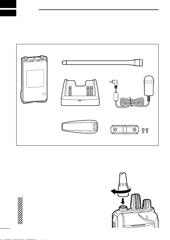
1 ACCESSORIES ......................................................................... 1–4
■Supplied accessories.................................................................. 1
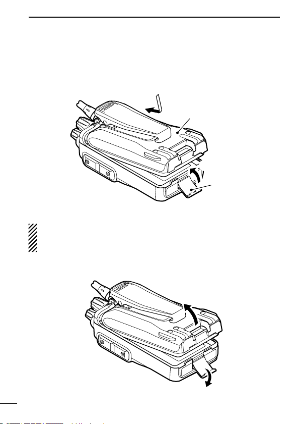
■Accessory attachments .............................................................. 1
2 PANEL DESCRIPTION ............................................................ 5–11
■Front, top and side panels .......................................................... 5
■LED indicator .............................................................................. 7
■Programmable function keys ...................................................... 8
3 BASIC OPERATION .............................................................. 12–24
■Turning power ON..................................................................... 12
■Channel selection ..................................................................... 13
■Call procedure .......................................................................... 14
■Receiving and transmitting ....................................................... 15
■Setting the microphone gain..................................................... 18
■Setting the squelch level........................................................... 19
■Setting the Beep level............................................................... 20
■Setting the Ringer level............................................................. 21
■Output power level selection..................................................... 22
■Priority A channel selection ...................................................... 22
■MDC 1200 system operation .................................................... 23
■Lone Worker Emergency Call ................................................... 23
■Emergency Call ........................................................................ 24
4 IDAS OPERATION ................................................................. 25–30
■IDAS operation ......................................................................... 25
■IDAS-Trunk operation ............................................................... 25
■Receiving a call......................................................................... 26
■Transmitting a call ..................................................................... 28

vi
1
2
3
4
5
6
7
8
9
10
11
12
13
14
15
16
17
18
19
20
■Position data transmission........................................................ 30
■Status message transmission................................................... 30
■Encryption function ................................................................... 30
5 BATTERY CHARGING .......................................................... 31–41
■Caution (for the BP-264 ni-mh battery).................................... 31
■Caution (for the BP-265 Li-ion battery)................................... 33
■Battery chargers ....................................................................... 36
6 BATTERY CASE .......................................................................... 42
■Optional battery case (BP-263) ................................................ 42
7 OPTIONS ............................................................................... 43–48
■VOX function ............................................................................. 46
TABLE OF CONTENTS

■Accessory attachments
DFlexible antenna
Connect the flexible antenna to the an-
tenna connector.
CAUTION:
• NEVER HOLD just the antenna
when carrying the transceiver.
• Transmitting without an antenna will
damage the transceiver.
■Supplied accessories
The following accessories are supplied with the transceiver.
1
1ACCESSORIES
Battery pack*
Belt clip* Jack cover
(with screws)
Battery charger*AC adapter*
* Not supplied, or the shape is different, depending on the version.
Flexible antenna
(This illustration is for the VHF type.)

2
1
ACCESSORIES
1
2
3
4
5
6
7
8
9
10
11
12
13
14
15
16
17
18
19
20
DBelt clip
To attach the belt clip:
➥Slide the belt clip in the direction of the arrow until the belt clip
locks in place, and makes a ‘click’ sound.
Battery pack
Belt clip
To detach the belt clip:
qRemove the battery pack from the transceiver, if it is attached.
(p. 3)
wLift the tab up (q), and slide the belt clip in the direction of the
arrow (w).
w
q
Ta b

3
1ACCESSORIES
DBattery pack or case
To attach the battery pack or case:
q Fit the battery pack/case in the direction of the arrow, then close
it.
w Hook the latch until it makes a ‘click’ sound.
q
Latch
w
Battery pac
k/case
To remove the battery pack/case:
Be careful! The latch is tightly locked, so use caution when re-
leasing it. DO NOT use your finger nail. Use the edge of a coin
or screwdriver tip to carefully release it
.
qUnhook the latch.
wLift up the
battery pack/case
in the direction of the arrow.
q
w

4
1
ACCESSORIES
1
2
3
4
5
6
7
8
9
10
11
12
13
14
15
16
17
18
19
20
NEVER remove or attach the
battery pack/case
when the trans-
ceiver is wet or soiled. This may result in water or dust getting into
the transceiver,
battery pack/case,
and may result in them being
damaged.
NOTE: Keep the battery terminals clean. It’s a good idea to clean
the battery terminals once a week.
DJack cover
Attach the jack cover when the optional equipment is not used.
To attach the jack cover:
qAttach the jack cover to the
[SP MIC] jack.
wTighten the screws.
To detach the jack cover:
qRemove the screws with a
phillips screwdriver.
wDetach the jack cover to con-
nect the optional equipment.
w
w
w
q
q
q

5
2PANEL DESCRIPTION
■Front, top and side panels
Microphone
Speaker
r
w
e
q
y
u
i
t
LOWER KEY
UPPER KEY
PTT SWITCH
ANTENNA
CONNECTOR
ROTARY
SELECTOR
LED INDICATO
R
VOLUME
CONTROL
SPEAKER-
MICROPHONE
JACK
qROTARY SELECTOR
Rotate to select the pre-programmed memory channels or scan
lists, depending on the pre-programming.
wVOLUME CONTROL [VOL]
Rotate to turn the power ON or OFF, and adjust the audio level.

6
2
PANEL DESCRIPTION
eLED INDICATOR (p. 7)
➥Lights red* while transmitting.
*When the optional battery case is attached, the LED indicator
lights orange.
➥Lights green while receiving a signal, or when the squelch is
open.
➥Lights/blinks orange when the matched 2/5-tone code is re-
ceived, depending on the pre-programming.
rSPEAKER-MICROPHONE JACK [SP MIC]
Connect the optional speaker-microphone or VOX adapter
cable.
tLOWER KEY [Lower]
yUPPER KEY [Upper]
The desired function can be assigned by your dealer. (p. 8)
uPTT SWITCH [PTT]
Hold down to transmit; release to receive.
iANTENNA CONNECTOR
Connect the antenna.
1
2
3
4
5
6
7
8
9
10
11
12
13
14
15
16
17
18
19
20
Jack cover
NOTE: Attach the jack cover
when the optional equipment
is not used. (p. 4)

7
2PANEL DESCRIPTION
■LED indicator
The LED indicator indicates the status of various
parameters of the transceiver as follows;
(Ref.; R=Red, G=Green, O=Orange)
R* R*
TX Low BATT2
R* R* R* R*
O
O O
G G G G
G G
G G G G G G G G
R G R G R G R G R G R G R G R G
R O R O R O R O R O R O R O R O
G
G G
Clone Err
Clone TX/RX
Low BATT1
Low BATT2
Busy
F/S Scan
Call LED Blink
Call LED ON
TX Low BATT1
R*
TX
• TX: Lights Red while transmitting a signal.
• RX: Lights Green while receiving a signal.
• Call LED (ON): Turns ON while receiving a matched 2/5-tone.
• Call LED (Blink): Blinks while receiving a matched 2/5-tone.
• Fast/Slow scan: Blinks when the Fast/Slow scan is activated.
• Low Battery 1: You should charge the battery. (blinks slowly)
• Low Battery 2: You must charge the battery. (blinks fast)
• TX low Battery 2: Very Low Battery was detected during TX mode.
• Channel Error: A non-programmed channel is selected.
* Lights (or blinks) orange when the optional battery case is attached.
• TX low Battery 1: Low Battery was detected during TX mode.

8
2
PANEL DESCRIPTION
■Programmable function keys
The following functions can be assigned to the [Upper] and [Lower]
programmable function keys.
Consult your Icom dealer or system operator for details concerning
your transceiver’s programming.
SCAN
Push to start and cancel the scanning operation.
• When the scan started with the Power ON Scan or Auto Scan func-
tion, push to pause the scanning operation. The paused scan re-
sumes after the specified time period has passed.
PRIORITY A CHANNEL, PRIORITY B CHANNEL
Push to select the Priority A or Priority B channel.
PRIORITY A CHANNEL (REWRITE),
PRIORITY B CHANNEL (REWRITE)
➥Push to select the Priority A or Priority B channel.
➥Hold down [Prio A (Rewrite)] or [Prio B (Rewrite)] for 1 second to
assign the operating channel to Priority A or Priority B channel,
respectively.
MEMORY CHANNELS 1, 2, 3, 4
Push to directly select memory channel 1, 2, 3 or 4, if programmed.
Consult your dealer for details.
LONE WORKER (p. 23)
➥Push to turn the Lone Worker function OFF.
➥Hold down to turn the Lone Worker function ON.
• When the Lone Worker function is turned ON, and no operation is
performed for the specified time period, the Emergency function is
automatically turned ON.
1
2
3
4
5
6
7
8
9
10
11
12
13
14
15
16
17
18
19
20

9
2PANEL DESCRIPTION
MONITOR, MONITOR (AUDIBLE)
➥Push to turn the CTCSS (DTCS) or 2/5-tone squelch Mute ON
or OFF.
• Only during LMR operation, push to open any squelch func-
tions, or deactivate any mute functions.
• Only during PMR operation, push to activate one or two of the
following functions* on each channel.
- Hold down to un-mute the channel (Audible mode).
- Push to mute the channel (Inaudible mode).
- Push to send a ‘reset code’ after the communication is finished.
*Ask your dealer for details.
NOTE: The un-mute condition may automatically return to
the mute condition, after a specified time period.
➥
Depending on the presetting, holding down this key for 1 sec-
ond cancels a scan.
LOCK
Hold down to electronically lock all programmable keys except
[Moni(Audi)], [Call] (including Call A and Call B), [Emergency],
Surveillance] and [Lone Worker].
HIGH/LOW (p. 22)
Select the transmit output power level temporarily or permanently,
depending on the presetting.
• Ask your dealer for the output power level for each selection.
TALK AROUND
➥Push to turn the Talk Around function OFF.
➥Hold down to turn the Talk Around function ON.
• The Talk Around function equalizes the transmit frequency to the
receive frequency for transceiver-to-transceiver communication.
DTMF AUTODIAL
Push to transmit a programmed DTMF code.

10
2
PANEL DESCRIPTION
WIDE/NARROW
➥Push to switch the IF bandwidth to Wide.
• The wide passband width can be selected from 20 or 25 kHz using
the optional cloning software (PMR operation only). Ask your dealer
for details.
➥Hold down to switch the IF bandwidth to Narrow.
CALL, CALL A, CALL B
Push to transmit a 2/5-tone code.
• Tone call transmission may be necessary before you call another sta-
tion, depending on your signalling system.
• [Call A] and/or [Call B] keys may be available when your system em-
ploys selective ‘Individual/Group’ calls. Ask your dealer which call is
assigned to each key.
EMERGENCY
Hold down for specified time period to transmit an emergency call.
• The emergency call transmits with beeps, and the LED lights red.
• The transceiver can transmit an emergency call without the beep
sounding and the LED indicator lighting. Ask your dealer for details.
• If you want to cancel the emergency call, hold down the key again
before transmitting the call.
• The emergency call is transmitted one time only, or repeatedly until re-
ceiving an acknowledgement signal, or until the power is turned OFF.
When a matched 5-tone code signal is received, the emergency func-
tion can be cancelled depending on the presetting. (PMR operation
only)
SURVEILLANCE
➥Push to turn the Surveillance function OFF.
➥Hold down to turn the Surveillance function ON.
• When this function is turned ON, the beep is not heard and the LED
does not light when a signal is received, or a key is pushed.
1
2
3
4
5
6
7
8
9
10
11
12
13
14
15
16
17
18
19
20

SIREN
Hold down for 1 second to emit a siren sound.
This function can be used for situations other than an emergency
alert, such as a security alarm for example.
The transceiver emits the siren sound until the power is turned
OFF.
ENCRYPTION
Push to turn the Voice Encryption function ON or OFF while operat-
ing in the digital mode.
ANNOUNCE
Push to turn the Channel Announce function ON or OFF.
• When this function is turned ON, the transceiver announces the posi-
tion of [ROTARY SELECTOR] between 1 and 16 when rotating [RO-
TARY SELECTOR] to a desired scale.
11
2PANEL DESCRIPTION

12
3
BASIC OPERATION
1
2
3
4
5
6
7
8
9
10
11
12
13
14
15
16
17
18
19
20
■Turning power ON
Prior to using the transceiver for the first time, the battery pack
must be fully charged for optimum life and operation. (p. 31)
➥ Rotate [VOL] to turn power ON.
D Battery type selection
The battery type must be selected according to the battery pack or
case when it is changed, but only the first time it is used.
Check the battery type before you begin the selection procedure.
One to three beep(s) sound in sequence, so you must repeat the
steps until the number of beeps matches your battery type.
For example, if your battery type is a Li-ion battery pack, you must
repeat the procedure until one beep is heard.
qSet
[ROTARY SELECTOR] to any
channel other than Channel 16.
w Rotate [VOL] to turn OFF the trans-
ceiver’s power.
e
While holding down [PTT], rotate
[VOL] to turn ON the power.
• You should hold [PTT] until the beep
sounds. (It takes approximately 5
second.)
• One beep sounds when the Li-ion
battery is selected.
• Two beeps sound when the battery case is selected.
• Three beeps sound when the Ni-MH battery is selected.
rAfter the beep sounds, release [PTT].
t Repeat steps wto runtil you select the attached battery type.
NOTE: This operation may not be available, depending on the
presetting. Ask your dealer for details.
[VOL]
[VOL]
[PTT]
[ROTARY SELECTOR]

■Channel selection
Several types of channel selecting methods are available. They
may differ, according to your system set up.
To select a desired operating channel, do one of the following.
• Rotate [ROTARY SELECTOR].
• Push one of memory channel keys, [MR-CH 1] to [MR-CH 4].
• Push one of these keys, [Prio A], [Prio B], [Prio A (Rewrite)] and
[Prio B (Rewrite)].
AUTOMATIC SCAN TYPE:
Selecting a channel is not necessary for this type. When turning ON
the power, the transceiver automatically starts scanning. Scanning
stops when a call is received.
NOTE: If the Move to Priority A channel at Power ON function
(p. 22) is turned ON, the transceiver does not start scanning at
power ON.
13
3BASIC OPERATION
This manual suits for next models
1
Table of contents
Other Icom Transceiver manuals

Icom
Icom IC-V82 User manual

Icom
Icom IC-A25 Installation guide

Icom
Icom M802 User manual

Icom
Icom IC-290E User manual

Icom
Icom IC-F510 User manual

Icom
Icom IC-F8100 User manual

Icom
Icom IC-M3EURO User manual

Icom
Icom iM710 User manual

Icom
Icom IC-7300 HF Plus Installation instructions

Icom
Icom IC-F4001 User manual

Icom
Icom IC-706MKII User manual

Icom
Icom IC-F7510 Series User manual

Icom
Icom IC-F7010 Series User manual

Icom
Icom IC-F4SR User manual

Icom
Icom IC-M1EURO V User manual

Icom
Icom iF3021T User manual

Icom
Icom IC-M200 User manual

Icom
Icom A25N 46 USA Installation guide

Icom
Icom IC-F3200DEX User manual

Icom
Icom IC-756 User manual